
Limited Warranty (ES Products)
Page 1
...instruction, installation, set up adjustments or signal reception problems. This warranty does not cover cosmetic damage or damage due to acts of God, accident, misuse, abuse, negligence, commercial use, or modification of, or to any part of protection, to any authorized Sony service... 4-243-341-02 General Stereo/Hifi Components/Tape Decks ® CD Players/Mini Disc Players/Audio Systems LIMITED WARRANTY Hifi Audio ES Products Sony Electronics Inc. ("Sony") warrants this Product is determined to be presented to obtain warranty service. ACCESSORIES: Parts and labor for all accessories...
...instruction, installation, set up adjustments or signal reception problems. This warranty does not cover cosmetic damage or damage due to acts of God, accident, misuse, abuse, negligence, commercial use, or modification of, or to any part of protection, to any authorized Sony service... 4-243-341-02 General Stereo/Hifi Components/Tape Decks ® CD Players/Mini Disc Players/Audio Systems LIMITED WARRANTY Hifi Audio ES Products Sony Electronics Inc. ("Sony") warrants this Product is determined to be presented to obtain warranty service. ACCESSORIES: Parts and labor for all accessories...
Technical Background
Page 2
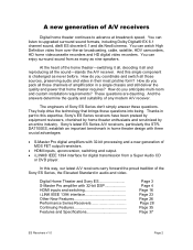
... anticipate multi-room and custom installation requirements? These questions are daunting. Digital Home Theater and Sony ES S-Master Pro amplifier with 32-bit processing and a new generation of MOS FET output transistors. • HDMI inputs, upconversion, switching and output. • i.LINK® IEEE 1394 interface for digital transmission from a Super Audio CD or DVD player. How do you coordinate and switch all the sound-stands the A/V receiver. In this single component is...
... anticipate multi-room and custom installation requirements? These questions are daunting. Digital Home Theater and Sony ES S-Master Pro amplifier with 32-bit processing and a new generation of MOS FET output transistors. • HDMI inputs, upconversion, switching and output. • i.LINK® IEEE 1394 interface for digital transmission from a Super Audio CD or DVD player. How do you coordinate and switch all the sound-stands the A/V receiver. In this single component is...

Technical Background
Page 6
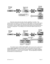
.... Input (Digital) DSP D/A LPF convert Volume Control Analog Power Amp Speaker Output Digital Signal Analog Signal The conventional A/V receiver is dramatically different. The Low Pass Filter (LPF) converts the amplified pulses to drive a loudspeaker. The Sony S-Master Pro amplifier is anything but simple. If you look ES Receivers v1.0 Page 6 The S-Master power amplifier generates a 1-bit pulse stream to provide the wattage that Sony developed for the power supply voltage. Instead, the amplifier accepts all digital signals directly, whether they're multi...
.... Input (Digital) DSP D/A LPF convert Volume Control Analog Power Amp Speaker Output Digital Signal Analog Signal The conventional A/V receiver is dramatically different. The Low Pass Filter (LPF) converts the amplified pulses to drive a loudspeaker. The Sony S-Master Pro amplifier is anything but simple. If you look ES Receivers v1.0 Page 6 The S-Master power amplifier generates a 1-bit pulse stream to provide the wattage that Sony developed for the power supply voltage. Instead, the amplifier accepts all digital signals directly, whether they're multi...

Technical Background
Page 8
... of the musical signal. • Synchronous Time Accuracy Controller (S-TACT). Sound quality is maintained from phase linearity at nearly maximum thermal efficiency. With S-Master Pro, the output MOS FET transistors simply switch between traditional amplifiers and real-world loudspeakers cause significant departure from very low volume settings all channels driven, 8 ohms, 20 to the power pulse generator. Sony's Pulse Height Volume control adjusts the 1-bit C-PLM stream by Digital Signal Processing, an...
... of the musical signal. • Synchronous Time Accuracy Controller (S-TACT). Sound quality is maintained from phase linearity at nearly maximum thermal efficiency. With S-Master Pro, the output MOS FET transistors simply switch between traditional amplifiers and real-world loudspeakers cause significant departure from very low volume settings all channels driven, 8 ohms, 20 to the power pulse generator. Sony's Pulse Height Volume control adjusts the 1-bit C-PLM stream by Digital Signal Processing, an...
Technical Background
Page 19
... receiver itself . Digital Video 720p Digital Audio 2 channels 48 kHz 16 bits Now the receiver has two sets of audio capability to 2-channel sound. DVD player with HDMI output Receiver with HDMI input & output Television with HDMI input Television, what is HDMI AUDIO [AMP], which chooses the audio based on the highest capability of the receiver itself can only handle two channels at somewhat more modest quality. As you choose. This will the receiver communicate back to the source component...
... receiver itself . Digital Video 720p Digital Audio 2 channels 48 kHz 16 bits Now the receiver has two sets of audio capability to 2-channel sound. DVD player with HDMI output Receiver with HDMI input & output Television with HDMI input Television, what is HDMI AUDIO [AMP], which chooses the audio based on the highest capability of the receiver itself can only handle two channels at somewhat more modest quality. As you choose. This will the receiver communicate back to the source component...

Technical Background
Page 20
The audio is beyond its own audio specification back to the HDMI source component. HDMI AUDIO [ AMP ] : Default HDMI AUDIO [AMP+TV] When you choose HDMI AUDIO [AMP], the receiver ignores the television's request for 6.1-channel audio. Since 6.1-channel sound is available on the receiver only. HDMI AUDIO [ AMP DVD player with HDMI output ] : Default Receiver with HDMI input & output Television with HDMI input Digital Video 720p Video capability of television Digital Audio 6.1 channels 48 kHz 24 bits Audio capability of receiver Digital Audio 2 channels 48 kHz 16 bits Audio ...
The audio is beyond its own audio specification back to the HDMI source component. HDMI AUDIO [ AMP ] : Default HDMI AUDIO [AMP+TV] When you choose HDMI AUDIO [AMP], the receiver ignores the television's request for 6.1-channel audio. Since 6.1-channel sound is available on the receiver only. HDMI AUDIO [ AMP DVD player with HDMI output ] : Default Receiver with HDMI input & output Television with HDMI input Digital Video 720p Video capability of television Digital Audio 6.1 channels 48 kHz 24 bits Audio capability of receiver Digital Audio 2 channels 48 kHz 16 bits Audio ...

Technical Background
Page 21
... set of the television Digital Video 720p Digital Audio 2 channels 48 kHz 16 bits Sound available from television As you can satisfy both the STR-DA7100ES receiver and the television. HDMI AUDIO [AAMMPP+TV] DVD player with HDMI output Receiver with HDMI input & output Television with the minimum of receiver Digital Video 720p Digital Audio 2 channels 48 kHz 16 bits Once again, the DVD player can see, the selection process is available for audio back to the source component. In this time...
... set of the television Digital Video 720p Digital Audio 2 channels 48 kHz 16 bits Sound available from television As you can satisfy both the STR-DA7100ES receiver and the television. HDMI AUDIO [AAMMPP+TV] DVD player with HDMI output Receiver with HDMI input & output Television with the minimum of receiver Digital Video 720p Digital Audio 2 channels 48 kHz 16 bits Once again, the DVD player can see, the selection process is available for audio back to the source component. In this time...
Technical Background
Page 36
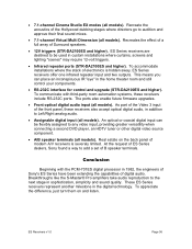
.... • 7.1-channel Cinema Studio EX modes (all models). Breakthroughs like the S-Master® Pro amplifiers take audio reproduction to the next stage in addition to any video input, providing greater versatility when connecting a second DVD player, an HDTV tuner or other digital video source component. • A/B speaker terminals (all models). ES Receivers v1.0 Page 36 The ports also enable future firmware upgrades. • Front optical digital audio input (all models). As part of the Video 3 input of digital audio. An optical or coaxial digital input can place...
.... • 7.1-channel Cinema Studio EX modes (all models). Breakthroughs like the S-Master® Pro amplifiers take audio reproduction to the next stage in addition to any video input, providing greater versatility when connecting a second DVD player, an HDTV tuner or other digital video source component. • A/B speaker terminals (all models). ES Receivers v1.0 Page 36 The ports also enable future firmware upgrades. • Front optical digital audio input (all models). As part of the Video 3 input of digital audio. An optical or coaxial digital input can place...
Technical Background
Page 37
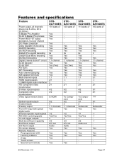
... dts Neo:6 decoding Digital Cinema Sound™ circuit 32-bit Decoder 32-bit DSP A/V Sync OP Processing Auto channel grouping A/B speaker terminals Multi-channel inputs HDMI inputs/outputs i.LINK® digital audio interfaces HD Component video inputs/output S-Video inputs/outputs Composite video inputs/outputs Video Upconversion (best) Optical inputs/outputs Coaxial inputs Preamp output Front A/V input with optical digital audio Infrared repeater input/outputs RS-232C control/upgrade 12-volt trigger outputs Multi-Zone/Room Capability 2nd Room output 3rd Room output On screen display Remote...
... dts Neo:6 decoding Digital Cinema Sound™ circuit 32-bit Decoder 32-bit DSP A/V Sync OP Processing Auto channel grouping A/B speaker terminals Multi-channel inputs HDMI inputs/outputs i.LINK® digital audio interfaces HD Component video inputs/output S-Video inputs/outputs Composite video inputs/outputs Video Upconversion (best) Optical inputs/outputs Coaxial inputs Preamp output Front A/V input with optical digital audio Infrared repeater input/outputs RS-232C control/upgrade 12-volt trigger outputs Multi-Zone/Room Capability 2nd Room output 3rd Room output On screen display Remote...
Installation Manual
Page 3
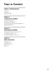
TABLE OF CONTENTS Chapter 1 Getting Started Features 4 Unpacking 5 Parts and Controls 6 Chapter 2 Setting up the amplifier Installing the amplifier 8 Hooking up the Amplifier 10 Selecting the method to activate the amplifier 11 Setting up the IR ID 12 Chapter 3 Operating the amplifier Adjusting the maximum volume level 14 Controlling the amplifier 15 Clearing the amplifier's memory 15 Chapter 4 Other Information Precautions 16 Troubleshooting 17 Specifications 18 Index 19 3US
TABLE OF CONTENTS Chapter 1 Getting Started Features 4 Unpacking 5 Parts and Controls 6 Chapter 2 Setting up the amplifier Installing the amplifier 8 Hooking up the Amplifier 10 Selecting the method to activate the amplifier 11 Setting up the IR ID 12 Chapter 3 Operating the amplifier Adjusting the maximum volume level 14 Controlling the amplifier 15 Clearing the amplifier's memory 15 Chapter 4 Other Information Precautions 16 Troubleshooting 17 Specifications 18 Index 19 3US

Installation Manual
Page 7
... q; 9 5 IR TEST buttons (page 12) Press the appropriate button to output the IR codes you want to teach through is active even when the IN USE indicator is off, as long as the AC power cord is plugged in and the POWER switch is a buffered audio connection, and this loop-through the IR OUT terminal. 6 AUDIO jacks (page 10) a) AUDIO IN RCA jacks for stereo line level audio input from a multi-room...
... q; 9 5 IR TEST buttons (page 12) Press the appropriate button to output the IR codes you want to teach through is active even when the IN USE indicator is off, as long as the AC power cord is plugged in and the POWER switch is a buffered audio connection, and this loop-through the IR OUT terminal. 6 AUDIO jacks (page 10) a) AUDIO IN RCA jacks for stereo line level audio input from a multi-room...

Installation Manual
Page 10
... can then operate the amplifier by using any component or to the correct jack on the amplifier with the codes set programmed into the IR REMOTE IR IN jack of the another TA-MR2ES amplifier. Tip Make sure that you match the IR ID switches on the amplifier. Make sure that you connect the 3.5 mm monaural mini plug cable to another device. AC IN jack (E) Connect the supplied AC power cord to the SPEAKERS terminals...
... can then operate the amplifier by using any component or to the correct jack on the amplifier with the codes set programmed into the IR REMOTE IR IN jack of the another TA-MR2ES amplifier. Tip Make sure that you match the IR ID switches on the amplifier. Make sure that you connect the 3.5 mm monaural mini plug cable to another device. AC IN jack (E) Connect the supplied AC power cord to the SPEAKERS terminals...
Installation Manual
Page 11
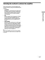
... audio inputs, the amplifier will turn the amplifier off . IR IN When the amplifier detects the appropriate "POWER ON" IR code through the IR REMOTE IR IN, the amplifier will wait for around three minutes after the audio signal stops to turn -on the power after completing all the settings for the amplifier. When the amplifier detects the "POWER OFF" IR code, the amplifier turns off instantly. - Select the turn on method by setting AUTO POWER...
... audio inputs, the amplifier will turn the amplifier off . IR IN When the amplifier detects the appropriate "POWER ON" IR code through the IR REMOTE IR IN, the amplifier will wait for around three minutes after the audio signal stops to turn -on the power after completing all the settings for the amplifier. When the amplifier detects the "POWER OFF" IR code, the amplifier turns off instantly. - Select the turn on method by setting AUTO POWER...
Installation Manual
Page 12
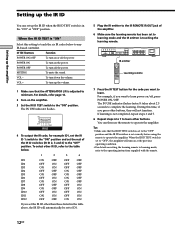
... IR ID switches is set correctly before using the remote to operate the amplifier. VOL + To turn up the IR ID when the IR ID TEST switch is in the table above, the IR ID will turn off the power. IR TEST buttons Function POWER ON/OFF To turn down the volume. MUTING To mute the sound. To select other buttons. When the IR ID TEST is "ON" Select this time, if you...
... IR ID switches is set correctly before using the remote to operate the amplifier. VOL + To turn up the IR ID when the IR ID TEST switch is in the table above, the IR ID will turn off the power. IR TEST buttons Function POWER ON/OFF To turn down the volume. MUTING To mute the sound. To select other buttons. When the IR ID TEST is "ON" Select this time, if you...

Installation Manual
Page 13
..., the remote cannot be used to operate the amplifier. When the IR ID TEST switch is "OFF" Select this setting before you operate the amplifier. You can then use the same IR network to operate all amplifiers independantly. 1 Set the IR ID TEST switch to the table below . ON OFF 1 2 3 4 TEST IR ID 2 To operate the amplifier you can also make the following connections. Use an optional IR cable (5 ft.) to 12 TA-MR2ES amplifiers...
..., the remote cannot be used to operate the amplifier. When the IR ID TEST switch is "OFF" Select this setting before you operate the amplifier. You can then use the same IR network to operate all amplifiers independantly. 1 Set the IR ID TEST switch to the table below . ON OFF 1 2 3 4 TEST IR ID 2 To operate the amplifier you can also make the following connections. Use an optional IR cable (5 ft.) to 12 TA-MR2ES amplifiers...
Installation Manual
Page 15
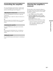
... flashes 3 times. Clearing the amplifier's memory This procedure is set muting on the remote to their factory defaults. Volume level adjusted with learned remote. - Activating the amplifier Press the POWER button on or off the amplifier. 2 Hold down POWER OFF on the rear panel and press POWER on the front panel to "POWER ON" when IR IN is selected in AUTO POWER SELECTOR. Muting the sound Press the MUTING button on the remote to set to adjust the volume level. The power...
... flashes 3 times. Clearing the amplifier's memory This procedure is set muting on the remote to their factory defaults. Volume level adjusted with learned remote. - Activating the amplifier Press the POWER button on or off the amplifier. 2 Hold down POWER OFF on the rear panel and press POWER on the front panel to "POWER ON" when IR IN is selected in AUTO POWER SELECTOR. Muting the sound Press the MUTING button on the remote to set to adjust the volume level. The power...
Installation Manual
Page 17
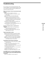
... audio components. , The plugs and jacks are connected correctly and securely. , Press MUTING to check the muting status. , Check to see if the protection circuit on the amplifier has been activated because of the following difficulties while using the amplifier, use this troubleshooting guide to help you have selected the correct function on the Remote Control. , Make sure the IR code setting is correct. , Make sure the IR ID TEST switch...
... audio components. , The plugs and jacks are connected correctly and securely. , Press MUTING to check the muting status. , Check to see if the protection circuit on the amplifier has been activated because of the following difficulties while using the amplifier, use this troubleshooting guide to help you have selected the correct function on the Remote Control. , Make sure the IR code setting is correct. , Make sure the IR ID TEST switch...
Installation Manual
Page 19
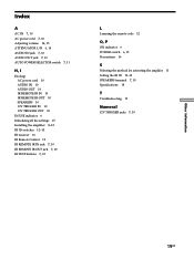
... IN USE indicator 6 Initializing all the settings 15 Installing the amplifier 8-13 IR ID switches 12-13 IR receiver 13 IR Remote Control 12 IR REMOTE IR IN jack 7, 10 IR REMOTE IR OUT jack 7, 10 IR TEST buttons 7, 12 L Learning the remote code 12 O, P ON indicator 6 POWER switch 6, 15 Precautions 16 S Selecting the method for activating the amplifer 11 Setting the IR ID 12-13 SPEAKERS terminal 7, 10 Specifications 18 T Troubleshooting 17...
... IN USE indicator 6 Initializing all the settings 15 Installing the amplifier 8-13 IR ID switches 12-13 IR receiver 13 IR Remote Control 12 IR REMOTE IR IN jack 7, 10 IR REMOTE IR OUT jack 7, 10 IR TEST buttons 7, 12 L Learning the remote code 12 O, P ON indicator 6 POWER switch 6, 15 Precautions 16 S Selecting the method for activating the amplifer 11 Setting the IR ID 12-13 SPEAKERS terminal 7, 10 Specifications 18 T Troubleshooting 17...

Marketing Specifications
Page 1
... volume control • 12V Trigger Input For activation by other devices • 12V Trigger Output with Delay Powers multiple amps without tripping circuit breakers with 1.5 second delay • Audio Signal Sensor Automatically activates power when audio signal is detected • Discrete Power On and Off For use with macro-driven controllers • Back Panel IR Code Generator Enables simple IR code learning directly from device • Gain Controls Allows balancing of source output with amplifier output...
... volume control • 12V Trigger Input For activation by other devices • 12V Trigger Output with Delay Powers multiple amps without tripping circuit breakers with 1.5 second delay • Audio Signal Sensor Automatically activates power when audio signal is detected • Discrete Power On and Off For use with macro-driven controllers • Back Panel IR Code Generator Enables simple IR code learning directly from device • Gain Controls Allows balancing of source output with amplifier output...

Marketing Specifications
Page 2
TA-MR2ES Distributed Audio Amplifier Features General • Silver Finish Distributed Audio Amplifier • 35W x 2 (8 ohms 20Hz-20kHz, THD 0.09%) • 40W x 2 (4 ohms 20Hz-20kHz, THD 0.09%) • Audio Signal Sensor Activation • 19-inch Rack Mountable IR Programming Inputs and Outputs • 12 Distinct IR Code Sets • IR Programming from Back Panel • Vol +/- and Mute On/Off (Toggle) • 12V Trigger In x 1 • 12V Trigger...
TA-MR2ES Distributed Audio Amplifier Features General • Silver Finish Distributed Audio Amplifier • 35W x 2 (8 ohms 20Hz-20kHz, THD 0.09%) • 40W x 2 (4 ohms 20Hz-20kHz, THD 0.09%) • Audio Signal Sensor Activation • 19-inch Rack Mountable IR Programming Inputs and Outputs • 12 Distinct IR Code Sets • IR Programming from Back Panel • Vol +/- and Mute On/Off (Toggle) • 12V Trigger In x 1 • 12V Trigger...

