
Operating Instructions
Page 1
3-289-200-11(1) Multi Channel AV Receiver Operating Instructions STR-DG920 ©2008 Sony Corporation
3-289-200-11(1) Multi Channel AV Receiver Operating Instructions STR-DG920 ©2008 Sony Corporation
Operating Instructions
Page 2
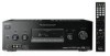
...try to correct the interference by one or more of electric shock to persons. Reorient or relocate the receiving antenna. - Increase the separation between the equipment and receiver. - CAUTION You are cautioned that interference will not occur in particular, specifies that to which can ...this equipment. Connect the equipment into an outlet on the apparatus. Do not install the appliance in this manual could void your Sony dealer regarding this equipment does cause harmful interference to comply with liquids, such as a bookcase or built-in the literature accompanying...
...try to correct the interference by one or more of electric shock to persons. Reorient or relocate the receiving antenna. - Increase the separation between the equipment and receiver. - CAUTION You are cautioned that interference will not occur in particular, specifies that to which can ...this equipment. Connect the equipment into an outlet on the apparatus. Do not install the appliance in this manual could void your Sony dealer regarding this equipment does cause harmful interference to comply with liquids, such as a bookcase or built-in the literature accompanying...
Operating Instructions
Page 3
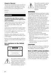
... code AA only". "M-crew Server" is used for model STR-DG920. In this manual, models of area code U is a trademark of Sony Corporation. All other technology or trademarks owned by Neural Audio Corporation, THX is shown on the display mean NeuralTHX Surround. This receiver incorporates High-Definition Multimedia Interface (HDMITM) technology. About This...
... code AA only". "M-crew Server" is used for model STR-DG920. In this manual, models of area code U is a trademark of Sony Corporation. All other technology or trademarks owned by Neural Audio Corporation, THX is shown on the display mean NeuralTHX Surround. This receiver incorporates High-Definition Multimedia Interface (HDMITM) technology. About This...
Operating Instructions
Page 4
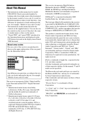
...the audio components.........19 4b: Connecting the video components ........24 5: Connecting the antennas (aerials 34 6: Preparing the receiver and the remote .....35 7: Operating the receiver using the GUI (Graphical User Interface 36 8: Selecting the speaker system 39 9: Calibrating the appropriate speaker settings ...74 Watching a DVD (One-Touch Play 75 Enjoying the TV sound from the speakers connected to the receiver (System Audio Control 76 Turning off the receiver with the TV (System Power Off 76 Other Operations Converting analog video input signals........ 77 Enjoying the...
...the audio components.........19 4b: Connecting the video components ........24 5: Connecting the antennas (aerials 34 6: Preparing the receiver and the remote .....35 7: Operating the receiver using the GUI (Graphical User Interface 36 8: Selecting the speaker system 39 9: Calibrating the appropriate speaker settings ...74 Watching a DVD (One-Touch Play 75 Enjoying the TV sound from the speakers connected to the receiver (System Audio Control 76 Turning off the receiver with the TV (System Power Off 76 Other Operations Converting analog video input signals........ 77 Enjoying the...
Operating Instructions
Page 6
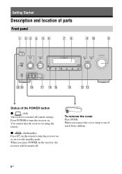
...Description and location of reach from children. 6US When you remove the cover, keep it to turn the receiver on . You cannot turn the receiver on the receiver, the receiver will be turned off (initial setting). When you press POWER on using the remote. To remove the cover... Press PUSH. qa ON/STANDBY POWER SPEAKERS (OFF/A/B/A+B) TONE MODE TONE TUNING MODE TUNING PHONES VIDEO 2 IN/PORTABLE AV IN VIDEO L ...
...Description and location of reach from children. 6US When you remove the cover, keep it to turn the receiver on . You cannot turn the receiver on the receiver, the receiver will be turned off (initial setting). When you press POWER on using the remote. To remove the cover... Press PUSH. qa ON/STANDBY POWER SPEAKERS (OFF/A/B/A+B) TONE MODE TONE TUNING MODE TUNING PHONES VIDEO 2 IN/PORTABLE AV IN VIDEO L ...
Operating Instructions
Page 7
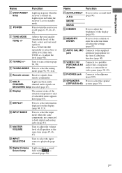
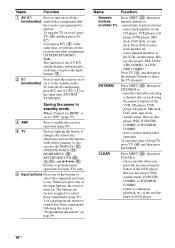
... with DCS is turned on. Adjusts the tonal quality (bass/treble level) of selectable items appears here (page 85). R VIDEO 2 IN/ PORTABLE AV IN jacks Connects to headphones (page 109). S PHONES jack Connects to a portable audio/video component such as a camcorder or video game (page 30...or a list of the front, center and surround speakers. Name Function N 2CH/A.DIRECT Press to select bass or treble level, then turn the receiver on the display (page 84, 113). Press TONE MODE repeatedly to select a sound field A.F.D. (page 96). Q AUTO CAL MIC jack Connects...
... with DCS is turned on. Adjusts the tonal quality (bass/treble level) of selectable items appears here (page 85). R VIDEO 2 IN/ PORTABLE AV IN jacks Connects to headphones (page 109). S PHONES jack Connects to a portable audio/video component such as a camcorder or video game (page 30...or a list of the front, center and surround speakers. Name Function N 2CH/A.DIRECT Press to select bass or treble level, then turn the receiver on the display (page 84, 113). Press TONE MODE repeatedly to select a sound field A.F.D. (page 96). Q AUTO CAL MIC jack Connects...
Operating Instructions
Page 8
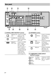
... player, TV, satellite tuner, etc. (page18, 27, 29). B ANTENNA section FM ANTENNA jack Connects to the FM wire antenna (aerial) supplied with this receiver (page 34). The image is output to a TV or a projector while the sound can be output from a TV or/and speakers connected to the AM... loop antenna (aerial) supplied with this receiver (page 25). AM ANTENNA terminals Connects to this receiver (page 34). C COMPONENT VIDEO INPUT/ OUTPUT section Green (Y) Blue (PB/CB) Y, PB/CB, PR/CR IN/ OUT* jacks ...
... player, TV, satellite tuner, etc. (page18, 27, 29). B ANTENNA section FM ANTENNA jack Connects to the FM wire antenna (aerial) supplied with this receiver (page 34). The image is output to a TV or a projector while the sound can be output from a TV or/and speakers connected to the AM... loop antenna (aerial) supplied with this receiver (page 25). AM ANTENNA terminals Connects to this receiver (page 34). C COMPONENT VIDEO INPUT/ OUTPUT section Green (Y) Blue (PB/CB) Y, PB/CB, PR/CR IN/ OUT* jacks ...
Operating Instructions
Page 9
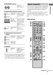
... Connects to jack subwoofer (page 16). Black AUDIO OUT Connects to speakers (page 16). You can use the supplied remote to operate the receiver and to control the Sony audio/video components that the remote is assigned to a VCR, DVD player, etc. (page 27-30). E AUDIO INPUT/OUTPUT section AUDIO IN/ ... HDMI OUT jack to a Super Audio CD player, etc. (page 18, 20, 23). RM-AAP023 wh wg wf wd ws wa ?/1 THEATER RM SET UP AV ?/1 SYSTEM STANDBY SHIFT TV AMP 1 VIDEO 1 2 VIDEO 2 4 5 DVD SAT 7 8 MD/ TAPE SA-CD/ CD -/-- 0/10 PHONO MULTI IN CLEAR/>10 XM 3 BD 6 TV 9 TUNER ...
... Connects to jack subwoofer (page 16). Black AUDIO OUT Connects to speakers (page 16). You can use the supplied remote to operate the receiver and to control the Sony audio/video components that the remote is assigned to a VCR, DVD player, etc. (page 27-30). E AUDIO INPUT/OUTPUT section AUDIO IN/ ... HDMI OUT jack to a Super Audio CD player, etc. (page 18, 20, 23). RM-AAP023 wh wg wf wd ws wa ?/1 THEATER RM SET UP AV ?/1 SYSTEM STANDBY SHIFT TV AMP 1 VIDEO 1 2 VIDEO 2 4 5 DVD SAT 7 8 MD/ TAPE SA-CD/ CD -/-- 0/10 PHONO MULTI IN CLEAR/>10 XM 3 BD 6 TV 9 TUNER ...
Operating Instructions
Page 10
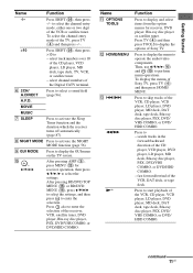
...press numeric buttons to - Press SHIFT (X), then press ENT/MEM to - enter the value after selecting a channel, disc or track using the numeric buttons of Sony TV, press TV (D) and then press ENT/MEM. To enter the value of the VCR, CD player, DVD player, LD player, MD deck, DAT ...tuner, Bluray disc player, PSX, DVD/ VHS COMBO, or DVD/ HDD COMBO. Name Function A AV ?/1 Press to turn on or off the (on/standby) audio/video components that the remote is set it will turn off the receiver and other components (SYSTEM STANDBY). C AMP Press to light up the button. D TV Press...
...press numeric buttons to - Press SHIFT (X), then press ENT/MEM to - enter the value after selecting a channel, disc or track using the numeric buttons of Sony TV, press TV (D) and then press ENT/MEM. To enter the value of the VCR, CD player, DVD player, LD player, MD deck, DAT ...tuner, Bluray disc player, PSX, DVD/ VHS COMBO, or DVD/ HDD COMBO. Name Function A AV ?/1 Press to turn on or off the (on/standby) audio/video components that the remote is set it will turn off the receiver and other components (SYSTEM STANDBY). C AMP Press to light up the button. D TV Press...
Operating Instructions
Page 11
..., DVD/ VHS COMBO, or DVD/ HDD COMBO. search tracks in the forward/backward direction of Sony TV, press TV (D) and then press HOME/ MENU. A.F.D. Press also to skip tracks of the receiver, VCR, satellite tuner, DVD player, Blu-ray disc player, PSX, DVD/VHS COMBO, or DVD.../HDD COMBO. Then, use V/v/B/b (J) and (J) to start playback of Sony TV. Press to perform menu operations. I GUI MODE Press to activate the Sleep Timer function and the duration which the receiver turns off automatically (page 87). continued 11US MOVIE MUSIC G SLEEP Press to display the...
..., DVD/ VHS COMBO, or DVD/ HDD COMBO. search tracks in the forward/backward direction of Sony TV, press TV (D) and then press HOME/ MENU. A.F.D. Press also to skip tracks of the receiver, VCR, satellite tuner, DVD player, Blu-ray disc player, PSX, DVD/VHS COMBO, or DVD.../HDD COMBO. Then, use V/v/B/b (J) and (J) to start playback of Sony TV. Press to perform menu operations. I GUI MODE Press to activate the Sleep Timer function and the duration which the receiver turns off automatically (page 87). continued 11US MOVIE MUSIC G SLEEP Press to display the...
Operating Instructions
Page 13
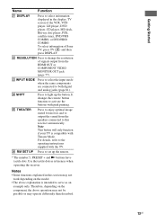
... Press to select the input mode when the same components are connected to select information displayed in this receiver automatically. Z RM SET UP Press to set up the button. Notes • Some functions explained ... satellite tuner, DVD/VHS COMBO, or DVD/HDD COMBO. For details, refer to serve as references when operating the receiver. Therefore, depending on the model. • The above operation may not be possible or may operate differently than described...77). It changes the remote button function to change the resolution of Sony TV, press TV (D) and then press DISPLAY.
... Press to select the input mode when the same components are connected to select information displayed in this receiver automatically. Z RM SET UP Press to set up the button. Notes • Some functions explained ... satellite tuner, DVD/VHS COMBO, or DVD/HDD COMBO. For details, refer to serve as references when operating the receiver. Therefore, depending on the model. • The above operation may not be possible or may operate differently than described...77). It changes the remote button function to change the resolution of Sony TV, press TV (D) and then press DISPLAY.
Operating Instructions
Page 14
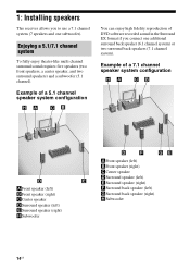
1: Installing speakers This receiver allows you connect one subwoofer). Enjoying a 5.1/7.1 channel system To fully enjoy theater-like multi channel surround sound requires five speakers (two front speakers, a center speaker, ...
1: Installing speakers This receiver allows you connect one subwoofer). Enjoying a 5.1/7.1 channel system To fully enjoy theater-like multi channel surround sound requires five speakers (two front speakers, a center speaker, ...
Operating Instructions
Page 17
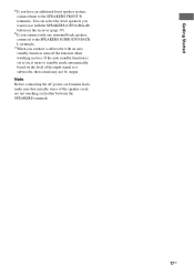
... to the SPEAKERS FRONT B terminals. Getting Started a)If you connect only one surround back speaker, connect it turns to standby mode automatically based on the receiver (page 39). If the auto standby function is set to on, it to a subwoofer, then sound may not be output. Note Before connecting the AC...
... to the SPEAKERS FRONT B terminals. Getting Started a)If you connect only one surround back speaker, connect it turns to standby mode automatically based on the receiver (page 39). If the auto standby function is set to on, it to a subwoofer, then sound may not be output. Note Before connecting the AC...
Operating Instructions
Page 18
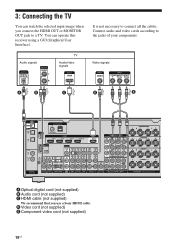
Connect audio and video cords according to connect all the cables. You can watch the selected input image when you use a Sony HDMI cable. It is not necessary to the jacks of your components. Audio signals TV Audio/video signals Video signals A B C D E TV OPTICAL IN ANTENNA FM ... HDMI OUT or MONITOR OUT jack to a TV. D Video cord (not supplied) E Component video cord (not supplied) 18US 3: Connecting the TV You can operate this receiver using a GUI (Graphical User Interface).
Connect audio and video cords according to connect all the cables. You can watch the selected input image when you use a Sony HDMI cable. It is not necessary to the jacks of your components. Audio signals TV Audio/video signals Video signals A B C D E TV OPTICAL IN ANTENNA FM ... HDMI OUT or MONITOR OUT jack to a TV. D Video cord (not supplied) E Component video cord (not supplied) 18US 3: Connecting the TV You can operate this receiver using a GUI (Graphical User Interface).
Operating Instructions
Page 19
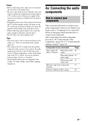
... If the power supply of the TV to "Fixed" if it can be switched between the TV and the antenna (aerial), the image on the receiver when the video and audio of a playback component are compatible with 32 kHz, 44.1 kHz, 48 kHz, and 96 kHz sampling frequencies. 4a: Connecting... to "4b: Connecting the video components" (page 24) or "5: Connecting the antennas (aerials)" (page 34). After connecting your audio components to a TV via the receiver. For details, see "Notes on converting video signals" (page 32). • The sound of the TV is transmitted. • Depending on the status of the...
... If the power supply of the TV to "Fixed" if it can be switched between the TV and the antenna (aerial), the image on the receiver when the video and audio of a playback component are compatible with 32 kHz, 44.1 kHz, 48 kHz, and 96 kHz sampling frequencies. 4a: Connecting... to "4b: Connecting the video components" (page 24) or "5: Connecting the antennas (aerials)" (page 34). After connecting your audio components to a TV via the receiver. For details, see "Notes on converting video signals" (page 32). • The sound of the TV is transmitted. • Depending on the status of the...
Operating Instructions
Page 20
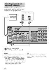
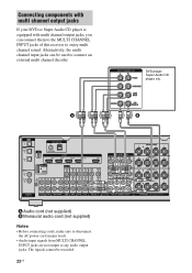
... with digital audio output jack The following illustration shows how to MULTI CHANNEL INPUT or SA-CD/CD IN jacks (analog input jack) on the receiver.
... with digital audio output jack The following illustration shows how to MULTI CHANNEL INPUT or SA-CD/CD IN jacks (analog input jack) on the receiver.
Operating Instructions
Page 21
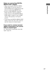
... unused input See "Enjoying the sound/images from other inputs" (page 82). 21US If you want to handle with care when placing or moving the receiver. • To disconnect the DIGITAL MEDIA PORT adapter, squeeze the sides of the connector, since the connector is locked in . • As the connector of...
... unused input See "Enjoying the sound/images from other inputs" (page 82). 21US If you want to handle with care when placing or moving the receiver. • To disconnect the DIGITAL MEDIA PORT adapter, squeeze the sides of the connector, since the connector is locked in . • As the connector of...
Operating Instructions
Page 22
.... 22US DVD player, Super Audio CD player, etc. Alternatively, the multi channel input jacks can connect them to the MULTI CHANNEL INPUT jacks of this receiver to connect an external multi channel decoder. A B TV OPTICAL IN ANTENNA FM AM OPTICAL VIDEO 1 IN SAT IN XM SAT IN HDMI BD IN DVD...
.... 22US DVD player, Super Audio CD player, etc. Alternatively, the multi channel input jacks can connect them to the MULTI CHANNEL INPUT jacks of this receiver to connect an external multi channel decoder. A B TV OPTICAL IN ANTENNA FM AM OPTICAL VIDEO 1 IN SAT IN XM SAT IN HDMI BD IN DVD...
Operating Instructions
Page 24
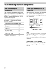
...be connected" below for up-converting video signals. If the power supply of a playback component are being output to a TV via the receiver. 4b: Connecting the video components How to connect your components This section describes how to connect your components, proceed to "5: Connecting the ... components. After connecting all your video components to the jacks on the receiver when the video and audio of the receiver is not turned on the connecting jack. Select the connection according to this receiver. Refer to connect each component. For details, see page 31. 24US...
...be connected" below for up-converting video signals. If the power supply of a playback component are being output to a TV via the receiver. 4b: Connecting the video components How to connect your components This section describes how to connect your components, proceed to "5: Connecting the ... components. After connecting all your video components to the jacks on the receiver when the video and audio of the receiver is not turned on the connecting jack. Select the connection according to this receiver. Refer to connect each component. For details, see page 31. 24US...
Operating Instructions
Page 25
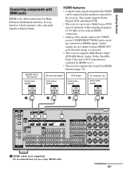
... player Audio/video signals DVD player Audio/video signals TV, projector, etc. HDMI features • A digital audio signals transmitted by HDMI ver1.3. • This receiver supports the Control for HighDefinition Multimedia Interface. Audio/video signals A A A A TV OPTICAL IN ANTENNA FM AM OPTICAL VIDEO 1 IN SAT IN XM SAT IN... R FRONT SURROUND SUR BACK SUBWOOFER VIDEO 1 SUBWOOFER MULTI CHANNEL INPUT SURROUND BACK R L SURROUND R L R FRONT B L FRONT A R L SPEAKERS A HDMI cable (not supplied) We recommend that you use a Sony HDMI cable. continued 25US
... player Audio/video signals DVD player Audio/video signals TV, projector, etc. HDMI features • A digital audio signals transmitted by HDMI ver1.3. • This receiver supports the Control for HighDefinition Multimedia Interface. Audio/video signals A A A A TV OPTICAL IN ANTENNA FM AM OPTICAL VIDEO 1 IN SAT IN XM SAT IN... R FRONT SURROUND SUR BACK SUBWOOFER VIDEO 1 SUBWOOFER MULTI CHANNEL INPUT SURROUND BACK R L SURROUND R L R FRONT B L FRONT A R L SPEAKERS A HDMI cable (not supplied) We recommend that you use a Sony HDMI cable. continued 25US


