Operating Instructions
Page 8
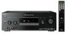
ql qkqj qh qg qf qd qs Function Lights up when the receiver is output from the SUBWOOFER jacks. D+" lights up when the audio signal is decoding Dolby Digital Plus signals. Note When playing a Dolby Digital format disc, be sure that you have .... THX Lights up when dynamic range compression is turned off or if headphones are connected. TrueHD wd ws wa w; "; "DTS-ES" lights up when the receiver is decoding DTS-ES signals. L Tuner indicators Lights up when INPUT MODE is a digital signal being input through the COAXIAL jack (page 82). Lights up...
ql qkqj qh qg qf qd qs Function Lights up when the receiver is output from the SUBWOOFER jacks. D+" lights up when the audio signal is decoding Dolby Digital Plus signals. Note When playing a Dolby Digital format disc, be sure that you have .... THX Lights up when dynamic range compression is turned off or if headphones are connected. TrueHD wd ws wa w; "; "DTS-ES" lights up when the receiver is decoding DTS-ES signals. L Tuner indicators Lights up when INPUT MODE is a digital signal being input through the COAXIAL jack (page 82). Lights up...

Operating Instructions
Page 10
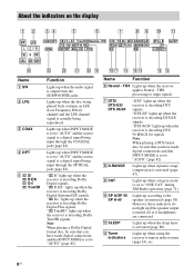
The image is output to a TV or a projector while the sound can be output from a TV or/and speakers connected to this receiver (page 23). 4 B ANTENNA section FM ANTENNA jack AM ANTENNA terminals Connects to a DVD jacks player, etc. Rear panel 12 1 3 TV OPTICAL IN VIDEO ... OUT IN DC5V 0.7A MAX L DMPORT AUDIO AUDIO AUDIO AUDIO AUDIO IN IN IN OUT IN OUT R SA-CD/CD/CD-R TV SAT DVD VIDEO 1 SUBWOOFER SURROUND BACK SURROUND L L CENTER R R SPEAKERS FRONT B R L FRONT A L R SPEAKERS 75 65 A DIGITAL INPUT/OUTPUT section OPTICAL IN Connects to the supplied FM wire ...
The image is output to a TV or a projector while the sound can be output from a TV or/and speakers connected to this receiver (page 23). 4 B ANTENNA section FM ANTENNA jack AM ANTENNA terminals Connects to a DVD jacks player, etc. Rear panel 12 1 3 TV OPTICAL IN VIDEO ... OUT IN DC5V 0.7A MAX L DMPORT AUDIO AUDIO AUDIO AUDIO AUDIO IN IN IN OUT IN OUT R SA-CD/CD/CD-R TV SAT DVD VIDEO 1 SUBWOOFER SURROUND BACK SURROUND L L CENTER R R SPEAKERS FRONT B R L FRONT A L R SPEAKERS 75 65 A DIGITAL INPUT/OUTPUT section OPTICAL IN Connects to the supplied FM wire ...
Operating Instructions
Page 11
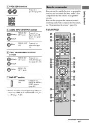
... OUT Connects to operate. VIDEO IN/ Yellow OUT* jacks Remote commander You can use the supplied remote to operate the receiver and to control the Sony audio/video components that the remote is assigned to a jack subwoofer (page 17). RM-AAP021 wj wh wg wf wd ws wa w; ?/1 THEATER RM SET UP... AV ?/1 SYSTEM STANDBY SHIFT TV AMP 1 VIDEO 1 4 DVD 7 -/-- 2 VIDEO 2 5 SAT 8 SA-CD/ CD 0/10 CLEAR/>10 XM 3 BD 6 TV 9 TUNER ENT/MEM...
... OUT Connects to operate. VIDEO IN/ Yellow OUT* jacks Remote commander You can use the supplied remote to operate the receiver and to control the Sony audio/video components that the remote is assigned to a jack subwoofer (page 17). RM-AAP021 wj wh wg wf wd ws wa w; ?/1 THEATER RM SET UP... AV ?/1 SYSTEM STANDBY SHIFT TV AMP 1 VIDEO 1 4 DVD 7 -/-- 2 VIDEO 2 5 SAT 8 SA-CD/ CD 0/10 CLEAR/>10 XM 3 BD 6 TV 9 TUNER ENT/MEM...
Operating Instructions
Page 16
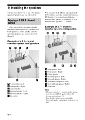
...speakers (two front speakers, a center speaker, and two surround speakers) and a subwoofer (5.1 channel). Example of DVD software recorded sound in the Surround EX format if you connect one subwoofer). Example of a 5.1 channel speaker system configuration You can enjoy high fidelity reproduction ...the surround back speaker behind the listening position (page 49). • Since the subwoofer does not emit highly directional signals, you can place it wherever you want. 1: Installing the speakers This receiver allows you to use a 7.1 channel system (7 speakers and one additional surround ...
...speakers (two front speakers, a center speaker, and two surround speakers) and a subwoofer (5.1 channel). Example of DVD software recorded sound in the Surround EX format if you connect one subwoofer). Example of a 5.1 channel speaker system configuration You can enjoy high fidelity reproduction ...the surround back speaker behind the listening position (page 49). • Since the subwoofer does not emit highly directional signals, you can place it wherever you want. 1: Installing the speakers This receiver allows you to use a 7.1 channel system (7 speakers and one additional surround ...

Operating Instructions
Page 17
... AUDIO AUDIO AUDIO AUDIO AUDIO IN IN IN IN OUT IN OUT SURROUND BACK SURROUND L L CENTER R R SPEAKERS FRONT B R L FRONT A L R CD/CD-R TV SAT DVD VIDEO 1 SUBWOOFER SPEAKERS A B SPEAKERS FRONT B B terminalsa) H G B A A Monaural audio cord (not supplied) B Speaker cord (not supplied) AFront speaker A (Left) BFront speaker A (Right) CCenter speaker DSurround speaker (Left) 10...
... AUDIO AUDIO AUDIO AUDIO AUDIO IN IN IN IN OUT IN OUT SURROUND BACK SURROUND L L CENTER R R SPEAKERS FRONT B R L FRONT A L R CD/CD-R TV SAT DVD VIDEO 1 SUBWOOFER SPEAKERS A B SPEAKERS FRONT B B terminalsa) H G B A A Monaural audio cord (not supplied) B Speaker cord (not supplied) AFront speaker A (Left) BFront speaker A (Right) CCenter speaker DSurround speaker (Left) 10...
Operating Instructions
Page 18
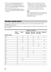
...a speaker pattern After you have an additional front speaker system, connect them to standby mode automatically based on the receiver (page 30). Speaker pattern 3/4.1 3/4 3/3.1 3/3 2/4.1 2/4 3/2.1 3/2 2/3.1 2/3 2/2.1 2/2 3/0.1 3/0 2/0.1 2/0 Front Center left/right Speaker connected Surround Surround Surround Subwoofer left/right back left back right a a a a a a a a a a a a a a a a a a a a a a a a a a a a a a a a a a a a a a a a a a a a a a a a a a a a a a a a 18US For details of each other between the SPEAKERS terminals. If the...
...a speaker pattern After you have an additional front speaker system, connect them to standby mode automatically based on the receiver (page 30). Speaker pattern 3/4.1 3/4 3/3.1 3/3 2/4.1 2/4 3/2.1 3/2 2/3.1 2/3 2/2.1 2/2 3/0.1 3/0 2/0.1 2/0 Front Center left/right Speaker connected Surround Surround Surround Subwoofer left/right back left back right a a a a a a a a a a a a a a a a a a a a a a a a a a a a a a a a a a a a a a a a a a a a a a a a a a a a a a a a 18US For details of each other between the SPEAKERS terminals. If the...

Operating Instructions
Page 19
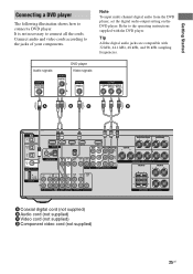
... OUT IN DC5V 0.7A MAX L DMPORT AUDIO AUDIO AUDIO AUDIO AUDIO IN IN IN OUT IN OUT R SA-CD/CD/CD-R TV SAT DVD VIDEO 1 SUBWOOFER SURROUND BACK SURROUND L L CENTER R R SPEAKERS FRONT B R L FRONT A L R SPEAKERS A Optical digital cord (not supplied) B Audio cord (not supplied) C HDMI cable (not supplied) We recommend that you... (not supplied) continued 19US It is not necessary to a TV. Getting Started 3: Connecting the TV You can watch the selected input image when you use a Sony HDMI cable.
... OUT IN DC5V 0.7A MAX L DMPORT AUDIO AUDIO AUDIO AUDIO AUDIO IN IN IN OUT IN OUT R SA-CD/CD/CD-R TV SAT DVD VIDEO 1 SUBWOOFER SURROUND BACK SURROUND L L CENTER R R SPEAKERS FRONT B R L FRONT A L R SPEAKERS A Optical digital cord (not supplied) B Audio cord (not supplied) C HDMI cable (not supplied) We recommend that you... (not supplied) continued 19US It is not necessary to a TV. Getting Started 3: Connecting the TV You can watch the selected input image when you use a Sony HDMI cable.

Operating Instructions
Page 21
... OUT IN DC5V 0.7A MAX L DMPORT AUDIO AUDIO AUDIO AUDIO AUDIO IN IN IN OUT IN OUT R SA-CD/CD/CD-R TV SAT DVD VIDEO 1 SUBWOOFER SURROUND BACK SURROUND L L CENTER R R SPEAKERS FRONT B R L FRONT A L R SPEAKERS A Audio cord (not supplied) 21US Getting Started 4a: Connecting the audio components Connecting a Super Audio CD/CD...
... OUT IN DC5V 0.7A MAX L DMPORT AUDIO AUDIO AUDIO AUDIO AUDIO IN IN IN OUT IN OUT R SA-CD/CD/CD-R TV SAT DVD VIDEO 1 SUBWOOFER SURROUND BACK SURROUND L L CENTER R R SPEAKERS FRONT B R L FRONT A L R SPEAKERS A Audio cord (not supplied) 21US Getting Started 4a: Connecting the audio components Connecting a Super Audio CD/CD...

Operating Instructions
Page 23
...HD Master Audio, Dolby TrueHD) and HDMI (Deep Color, x.v.Color). • This receiver supports the Control for HDMI function. This signal supports Dolby Digital, DTS, and Linear PCM. • This receiver can be output from the speakers connected to 8 channels) with a sampling frequency of 192... OUT IN DC5V 0.7A MAX L DMPORT AUDIO AUDIO AUDIO AUDIO AUDIO IN IN IN OUT IN OUT R SA-CD/CD/CD-R TV SAT DVD VIDEO 1 SUBWOOFER SURROUND BACK SURROUND L L CENTER R R SPEAKERS FRONT B R L FRONT A L R SPEAKERS A HDMI cable (not supplied) continued 23US It is the abbreviated ...
...HD Master Audio, Dolby TrueHD) and HDMI (Deep Color, x.v.Color). • This receiver supports the Control for HDMI function. This signal supports Dolby Digital, DTS, and Linear PCM. • This receiver can be output from the speakers connected to 8 channels) with a sampling frequency of 192... OUT IN DC5V 0.7A MAX L DMPORT AUDIO AUDIO AUDIO AUDIO AUDIO IN IN IN OUT IN OUT R SA-CD/CD/CD-R TV SAT DVD VIDEO 1 SUBWOOFER SURROUND BACK SURROUND L L CENTER R R SPEAKERS FRONT B R L FRONT A L R SPEAKERS A HDMI cable (not supplied) continued 23US It is the abbreviated ...
Operating Instructions
Page 25
... OUT IN DC5V 0.7A MAX L DMPORT AUDIO AUDIO AUDIO AUDIO AUDIO IN IN IN OUT IN OUT R SA-CD/CD/CD-R TV SAT DVD VIDEO 1 SUBWOOFER SURROUND BACK SURROUND L L CENTER R R SPEAKERS FRONT B R L FRONT A L R SPEAKERS A Coaxial digital cord (not supplied) B Audio cord (not supplied) C Video cord (not supplied) D Component video cord (not...
... OUT IN DC5V 0.7A MAX L DMPORT AUDIO AUDIO AUDIO AUDIO AUDIO IN IN IN OUT IN OUT R SA-CD/CD/CD-R TV SAT DVD VIDEO 1 SUBWOOFER SURROUND BACK SURROUND L L CENTER R R SPEAKERS FRONT B R L FRONT A L R SPEAKERS A Coaxial digital cord (not supplied) B Audio cord (not supplied) C Video cord (not supplied) D Component video cord (not...
Operating Instructions
Page 26
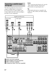
... OUT IN DC5V 0.7A MAX L DMPORT AUDIO AUDIO AUDIO AUDIO AUDIO IN IN IN OUT IN OUT R SA-CD/CD/CD-R TV SAT DVD VIDEO 1 SUBWOOFER SURROUND BACK SURROUND L L CENTER R R SPEAKERS FRONT B R L FRONT A L R SPEAKERS A Audio cord (not supplied) B Optical digital cord (not supplied) C Video cord (not supplied) D Component video cord (not...
... OUT IN DC5V 0.7A MAX L DMPORT AUDIO AUDIO AUDIO AUDIO AUDIO IN IN IN OUT IN OUT R SA-CD/CD/CD-R TV SAT DVD VIDEO 1 SUBWOOFER SURROUND BACK SURROUND L L CENTER R R SPEAKERS FRONT B R L FRONT A L R SPEAKERS A Audio cord (not supplied) B Optical digital cord (not supplied) C Video cord (not supplied) D Component video cord (not...
Operating Instructions
Page 27
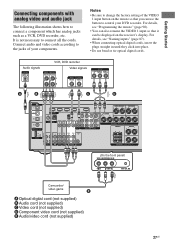
...; Do not bend or tie optical digital cords. Connect audio and video cords according to the jacks of the VIDEO 1 input button on the receiver's display. Audio signals VCR, DVD recorder Video signals A B C D TV OPTICAL IN VIDEO 1 IN SAT IN OPTICAL DVD IN COAXIAL DIGITAL...AUDIO AUDIO IN IN IN OUT IN OUT R SA-CD/CD/CD-R TV SAT DVD VIDEO 1 SUBWOOFER SURROUND BACK SURROUND L L CENTER R R SPEAKERS FRONT B R L FRONT A L R SPEAKERS (On the front panel) VIDEO 2 IN/PORTABLE AV IN VIDEO L AUDIO R AUTO CAL MIC Camcorder/ video game E A Optical digital cord (not ...
...; Do not bend or tie optical digital cords. Connect audio and video cords according to the jacks of the VIDEO 1 input button on the receiver's display. Audio signals VCR, DVD recorder Video signals A B C D TV OPTICAL IN VIDEO 1 IN SAT IN OPTICAL DVD IN COAXIAL DIGITAL...AUDIO AUDIO IN IN IN OUT IN OUT R SA-CD/CD/CD-R TV SAT DVD VIDEO 1 SUBWOOFER SURROUND BACK SURROUND L L CENTER R R SPEAKERS FRONT B R L FRONT A L R SPEAKERS (On the front panel) VIDEO 2 IN/PORTABLE AV IN VIDEO L AUDIO R AUTO CAL MIC Camcorder/ video game E A Optical digital cord (not ...

Operating Instructions
Page 28
... OUT IN DC5V 0.7A MAX L DMPORT AUDIO AUDIO AUDIO AUDIO AUDIO IN IN IN OUT IN OUT R SA-CD/CD/CD-R TV SAT DVD VIDEO 1 SUBWOOFER SURROUND BACK SURROUND L L CENTER R R SPEAKERS FRONT B R L FRONT A L R SPEAKERS Notes • To prevent noise pickup, keep the AM loop antenna (aerial) away from the...
... OUT IN DC5V 0.7A MAX L DMPORT AUDIO AUDIO AUDIO AUDIO AUDIO IN IN IN OUT IN OUT R SA-CD/CD/CD-R TV SAT DVD VIDEO 1 SUBWOOFER SURROUND BACK SURROUND L L CENTER R R SPEAKERS FRONT B R L FRONT A L R SPEAKERS Notes • To prevent noise pickup, keep the AM loop antenna (aerial) away from the...
Operating Instructions
Page 32
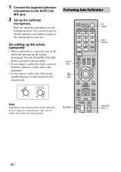
...VOL +/- 32US Place the optimizer microphone at the same height as your listening position. Note Depending on the subwoofer and turn on the characteristics of the subwoofer you connect a subwoofer with an auto standby function, set the value to the maximum. • If you are using, ...the setup distance value may be further away from the actual position. Performing Auto Calibration AUTO CAL ?/1 THEATER RM SET UP AV ?/1 SYSTEM STANDBY...
...VOL +/- 32US Place the optimizer microphone at the same height as your listening position. Note Depending on the subwoofer and turn on the characteristics of the subwoofer you connect a subwoofer with an auto standby function, set the value to the maximum. • If you are using, ...the setup distance value may be further away from the actual position. Performing Auto Calibration AUTO CAL ?/1 THEATER RM SET UP AV ?/1 SYSTEM STANDBY...
Operating Instructions
Page 33
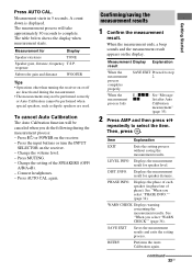
... the display. Change the volume level. - When the measurement ends, a beep sounds and the measurement result appears on the receiver. - DIST. WARN CHECK Displays warning concerning the measurement results. The measurement process will be canceled when you do the following ...the SPEAKERS (OFF/ A/B/A+B). - A count down is displayed. Measurement for speaker distance. response Subwoofer gain and distance WOOFER Tips • Operations other than turning the receiver on the receiver. - To cancel Auto Calibration The Auto Calibration function will take approximately 30 seconds to select ...
... the display. Change the volume level. - When the measurement ends, a beep sounds and the measurement result appears on the receiver. - DIST. WARN CHECK Displays warning concerning the measurement results. The measurement process will be canceled when you do the following ...the SPEAKERS (OFF/ A/B/A+B). - A count down is displayed. Measurement for speaker distance. response Subwoofer gain and distance WOOFER Tips • Operations other than turning the receiver on the receiver. - To cancel Auto Calibration The Auto Calibration function will take approximately 30 seconds to select ...
Operating Instructions
Page 34
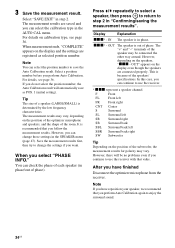
...the position of the optimizer microphone and speakers, and the shape of the speakers' specifications. Note You can select the position number to use the receiver. * xxx represent a speaker channel. Select a position number before you can change the settings if you can select the calibration type in "...left FR Front right CNT Center S Surround SL Surround left SR Surround right SB Surround back SBL Surround back left SBR Surround back right SW Subwoofer Tip Depending on the speakers, "xxx - However, you want. You can continue to step 2 in the AUTO CAL menu. Note If ...
...the position of the optimizer microphone and speakers, and the shape of the speakers' specifications. Note You can select the position number to use the receiver. * xxx represent a speaker channel. Select a position number before you can change the settings if you can select the calibration type in "...left FR Front right CNT Center S Surround SL Surround left SR Surround right SB Surround back SBL Surround back left SBR Surround back right SW Subwoofer Tip Depending on the speakers, "xxx - However, you want. You can continue to step 2 in the AUTO CAL menu. Note If ...
Operating Instructions
Page 35
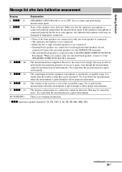
... the environment is connected only to allow proper measurement. xxx* : 33 W - You may be detected. The distance and position of a subwoofer cannot be damaged or improperly connected. • None of the receiver is set to perform the measurement in a quiet environment. xxx* : 42 W - The volume of the front speakers are not connected...
... the environment is connected only to allow proper measurement. xxx* : 33 W - You may be detected. The distance and position of a subwoofer cannot be damaged or improperly connected. • None of the receiver is set to perform the measurement in a quiet environment. xxx* : 42 W - The volume of the front speakers are not connected...

Operating Instructions
Page 43
... right speaker levelc) [SR LEVEL] Surround back speaker levelc) [SB LEVEL] Surround back left speaker levelc) [SBL LEVEL] Surround back right speaker levelc) [SBR LEVEL] Subwoofer levelc) [SW LEVEL] Dynamic range compressora) [D.
... right speaker levelc) [SR LEVEL] Surround back speaker levelc) [SB LEVEL] Surround back left speaker levelc) [SBL LEVEL] Surround back right speaker levelc) [SBR LEVEL] Subwoofer levelc) [SW LEVEL] Dynamic range compressora) [D.
Operating Instructions
Page 45
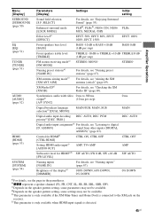
Synchronizes audio with video 0 ms to digital [D. Control for HDMIa) [CTRL:HDMI] CTRL ON, CTRL OFF Setting HDMI audio inputa) [AUDIO OUT] AMP, TV+AMP Subwoofer level for HDMIa)f) SW AUTO, SW 0 dB, SW +10 dB [SW LEVEL] DEC. For details, see "Aiming the XM antenna (aerial)" (page 69). AUTO, ... available when HDMI input signals is connected to TREBLE +10 dB TREBLE 0 dB (1dB per step) BASS 0 dB Front speakers treble level [TREBLE] FM station receiving modea) [FM MODE] Naming preset stationsa) [NAME IN] XM antenna aiming modee) [XM ANT AIM] XM Radio IDe) [XM ID] TREBLE -10 dB ...
Synchronizes audio with video 0 ms to digital [D. Control for HDMIa) [CTRL:HDMI] CTRL ON, CTRL OFF Setting HDMI audio inputa) [AUDIO OUT] AMP, TV+AMP Subwoofer level for HDMIa)f) SW AUTO, SW 0 dB, SW +10 dB [SW LEVEL] DEC. For details, see "Aiming the XM antenna (aerial)" (page 69). AUTO, ... available when HDMI input signals is connected to TREBLE +10 dB TREBLE 0 dB (1dB per step) BASS 0 dB Front speakers treble level [TREBLE] FM station receiving modea) [FM MODE] Naming preset stationsa) [NAME IN] XM antenna aiming modee) [XM ANT AIM] XM Radio IDe) [XM ID] TREBLE -10 dB ...
Operating Instructions
Page 46
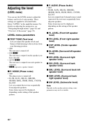
... right speaker level) x SB LEVEL (Surround back speaker level) x SBL LEVEL (Surround back left speaker level) x SBR LEVEL (Surround back right speaker level) x SW LEVEL (Subwoofer level) Note Depends on adjusting the parameters, see "Navigating through menus" (page 42) and "Overview of each speaker in the amplifier menus. LEVEL menu parameters...
... right speaker level) x SB LEVEL (Surround back speaker level) x SBL LEVEL (Surround back left speaker level) x SBR LEVEL (Surround back right speaker level) x SW LEVEL (Subwoofer level) Note Depends on adjusting the parameters, see "Navigating through menus" (page 42) and "Overview of each speaker in the amplifier menus. LEVEL menu parameters...


