
Operating Instructions
Page 9
...SUBWOOFER 3 C SPEAKERS section Connects to a DVD player, satellite tuner, or a Blu-ray disc player. HDMI IN/ OUT jacks Connects to the supplied speakers and subwoofer (page 17). E AUDIO INPUT section AUDIO IN White (L) jacks Red (R) Connects to the supplied FM wire antenna (page 24). Getting Started Rear ...DVD DVD IN L BD IN L OUT HDMI DC5V 700mA MAX R R AUDIO IN AUDIO IN AUDIO IN SA-CD/CD TV VIDEO 1 DMPORT 54 A ANTENNA section FM ANTENNA jack Connects to a Super Audio CD player, CD player, etc. (page 19, 22). 9GB AM ANTENNA terminals Connects to this receiver...
...SUBWOOFER 3 C SPEAKERS section Connects to a DVD player, satellite tuner, or a Blu-ray disc player. HDMI IN/ OUT jacks Connects to the supplied speakers and subwoofer (page 17). E AUDIO INPUT section AUDIO IN White (L) jacks Red (R) Connects to the supplied FM wire antenna (page 24). Getting Started Rear ...DVD DVD IN L BD IN L OUT HDMI DC5V 700mA MAX R R AUDIO IN AUDIO IN AUDIO IN SA-CD/CD TV VIDEO 1 DMPORT 54 A ANTENNA section FM ANTENNA jack Connects to a Super Audio CD player, CD player, etc. (page 19, 22). 9GB AM ANTENNA terminals Connects to this receiver...
Operating Instructions
Page 24
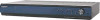
AC power cord (mains lead) AM SAT IN DVD IN TV DIGITAL L ANTENNA OPT IN OPT IN COAX IN VIDEO 2 DVD R AUDIO IN SA-CD/CD SUR L CENTER SUBWOOFER * The shape of the connector varies depending on the area code of this receiver. To the wall outlet 24GB Notes • To... pickup, keep the AM loop antenna away from the receiver and other components. • Be sure to disconnect the AC power cord (mains lead). Before connecting the antennas, be sure to fully extend the FM wire antenna. • After connecting the FM wire antenna, keep it as horizontal as possible. 4: Connecting...
AC power cord (mains lead) AM SAT IN DVD IN TV DIGITAL L ANTENNA OPT IN OPT IN COAX IN VIDEO 2 DVD R AUDIO IN SA-CD/CD SUR L CENTER SUBWOOFER * The shape of the connector varies depending on the area code of this receiver. To the wall outlet 24GB Notes • To... pickup, keep the AM loop antenna away from the receiver and other components. • Be sure to disconnect the AC power cord (mains lead). Before connecting the antennas, be sure to fully extend the FM wire antenna. • After connecting the FM wire antenna, keep it as horizontal as possible. 4: Connecting...
Operating Instructions
Page 69
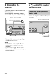
...power cord, or there is a power failure (page 56). Outdoor FM antenna Receiver AM Ground wire (not supplied) ANTENNA To ground Radio stations cannot be tuned in VIDEO menu. • Make sure the connected component is compatible with the System Audio Control function. • If the TV ...; Use a 75-ohm coaxial cable (not supplied) to connect the receiver to an outdoor FM antenna as shown below. To prevent a gas explosion, do not connect the ground wire to the operating instructions of a component connected to the TV. Additional Information continued 69GB Change the TV channel ...
...power cord, or there is a power failure (page 56). Outdoor FM antenna Receiver AM Ground wire (not supplied) ANTENNA To ground Radio stations cannot be tuned in VIDEO menu. • Make sure the connected component is compatible with the System Audio Control function. • If the TV ...; Use a 75-ohm coaxial cable (not supplied) to connect the receiver to an outdoor FM antenna as shown below. To prevent a gas explosion, do not connect the ground wire to the operating instructions of a component connected to the TV. Additional Information continued 69GB Change the TV channel ...
Operating Instructions
Page 72
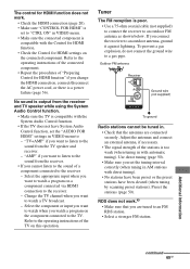
... when you change the AM tuning scale to 10 kHz (or 9 kHz), repeat the procedure. FM tuner section Tuning range 87.5 - 108.0 MHz Antenna FM wire antenna Antenna terminals 75 ohms, unbalanced Intermediate frequency 10.7 MHz AM tuner section Tuning range Area code Tuning scale 10 kHz step 9 kHz step U, UC... 165 W (for USA) 245 VA (for CANADA) TH 140 W Power consumption (during standby mode) 0.3 W (When "CONTROL FOR HDMI" in any AM station, turn off the receiver.
... when you change the AM tuning scale to 10 kHz (or 9 kHz), repeat the procedure. FM tuner section Tuning range 87.5 - 108.0 MHz Antenna FM wire antenna Antenna terminals 75 ohms, unbalanced Intermediate frequency 10.7 MHz AM tuner section Tuning range Area code Tuning scale 10 kHz step 9 kHz step U, UC... 165 W (for USA) 245 VA (for CANADA) TH 140 W Power consumption (during standby mode) 0.3 W (When "CONTROL FOR HDMI" in any AM station, turn off the receiver.

Operating Instructions
Page 74
... Instructions (this manual) Quick Setup Guide (1) Speaker Stand Installation Guide (HT-SF2300 only) (1) FM wire antenna (1) AM loop antenna (1) Remote commander • RM-AAU022 (1) (Models of area code U, UC, CA only) • RM-AAU023 (1) (Models of the component you are subject to change without notice. 74GB Design and specifications are using, see...
... Instructions (this manual) Quick Setup Guide (1) Speaker Stand Installation Guide (HT-SF2300 only) (1) FM wire antenna (1) AM loop antenna (1) Remote commander • RM-AAU022 (1) (Models of area code U, UC, CA only) • RM-AAU023 (1) (Models of the component you are subject to change without notice. 74GB Design and specifications are using, see...


