Service Manual
Page 3
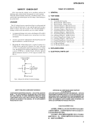
...Pin Function Description 23 4. COMPONENTS IDENTIFIED BY MARK 0 OR DOTTED LINE WITH MARK 0 ON THE SCHEMATIC DIAGRAMS AND IN THE PARTS LIST ARE CRITICAL TO SAFE OPERATION. REPLACE THESE COMPONENTS WITH SONY PARTS WHOSE PART NUMBERS APPEAR AS SHOWN IN THIS MANUAL OR IN SUPPLEMENTS PUBLISHED BY... "metallized" knobs, screws, and all exposed metal parts to any one of a passive VOM that have an accurate low-voltage scale. STR-DE475 SAFETY CHECK-OUT After correcting the original service problem, perform the following safety checks before releasing the set to check AC leakage. Check leakage...
...Pin Function Description 23 4. COMPONENTS IDENTIFIED BY MARK 0 OR DOTTED LINE WITH MARK 0 ON THE SCHEMATIC DIAGRAMS AND IN THE PARTS LIST ARE CRITICAL TO SAFE OPERATION. REPLACE THESE COMPONENTS WITH SONY PARTS WHOSE PART NUMBERS APPEAR AS SHOWN IN THIS MANUAL OR IN SUPPLEMENTS PUBLISHED BY... "metallized" knobs, screws, and all exposed metal parts to any one of a passive VOM that have an accurate low-voltage scale. STR-DE475 SAFETY CHECK-OUT After correcting the original service problem, perform the following safety checks before releasing the set to check AC leakage. Check leakage...
Service Manual
Page 7
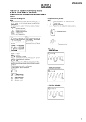
...model. C Q These are critical for safety. are omitted. BCE These are omitted. • A : B+ Line. • B : B- No mark : FM • Voltages are taken with a oscilloscope. • Circled numbers refer to waveforms. • Signal path. Voltage variations may be noted due to normal production ...233;s par une marque ! For printed wiring boards. SECTION 3 DIAGRAMS STR-DE475 THIS NOTE IS COMMON FOR PRINTED WIRING BOARDS AND SCHEMATIC DIAGRAMS. (In addition to this necessary note is printed in each block.) For schematic diagrams. Note: • All capacitors are in Ω and 1/4...
...model. C Q These are critical for safety. are omitted. BCE These are omitted. • A : B+ Line. • B : B- No mark : FM • Voltages are taken with a oscilloscope. • Circled numbers refer to waveforms. • Signal path. Voltage variations may be noted due to normal production ...233;s par une marque ! For printed wiring boards. SECTION 3 DIAGRAMS STR-DE475 THIS NOTE IS COMMON FOR PRINTED WIRING BOARDS AND SCHEMATIC DIAGRAMS. (In addition to this necessary note is printed in each block.) For schematic diagrams. Note: • All capacitors are in Ω and 1/4...
Service Manual
Page 20
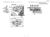
POWER SECTION -• See page 8 for Schematic Diagram. IC 1015 IC 1014 (Page 18) (Page 14) E model only 1-680-431- 20 20 VIDEO SECTION -• See page 8 for Circuit Boards Location. • See page 20 for Circuit Boards Location. (Page 14) (Page 14) IC 950 (Page 18) STR-DE475 3-14. 3-13. There are a few cases that the part printed on this diagram isn't mounted in this model. PRINTED WIRING BOARD - PRINTED WIRING BOARD -
POWER SECTION -• See page 8 for Schematic Diagram. IC 1015 IC 1014 (Page 18) (Page 14) E model only 1-680-431- 20 20 VIDEO SECTION -• See page 8 for Circuit Boards Location. • See page 20 for Circuit Boards Location. (Page 14) (Page 14) IC 950 (Page 18) STR-DE475 3-14. 3-13. There are a few cases that the part printed on this diagram isn't mounted in this model. PRINTED WIRING BOARD - PRINTED WIRING BOARD -


