Dimensions Diagram
Page 1
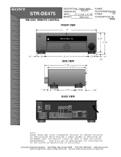
...OPTICAL... and measurements are approximate. SONY WILL NOT BE RESPONSIBLE FOR INACCURACIES IN THE DESIGN OR MANUFACTURE OF ENCLOSURES . STR-DE475 RM-U305 REMOTE CONTROL DESCRIPTION: Dolby Digital DIMENSIONS Receiver (WHD): 17" x ...5 3/4" x 11 7/8" WEIGHT: 15lbs 14oz POWER REQUIREMENTS:120V POWER 60H CONSUMPTION: 185 Watts FRONT VIEW 17" R FM102.7MHz A3 5 1/4" 5 3/4" 1/2" 1 7/8 " 12 1/4 " SIDE VIEW 11 7/8 " 10 1/2" 1 7/8 " 1/2" 1/2" 1 1/8" 1 7/8 " 5 1/4" 1 1/8 " BACK VIEW FM...
...OPTICAL... and measurements are approximate. SONY WILL NOT BE RESPONSIBLE FOR INACCURACIES IN THE DESIGN OR MANUFACTURE OF ENCLOSURES . STR-DE475 RM-U305 REMOTE CONTROL DESCRIPTION: Dolby Digital DIMENSIONS Receiver (WHD): 17" x ...5 3/4" x 11 7/8" WEIGHT: 15lbs 14oz POWER REQUIREMENTS:120V POWER 60H CONSUMPTION: 185 Watts FRONT VIEW 17" R FM102.7MHz A3 5 1/4" 5 3/4" 1/2" 1 7/8 " 12 1/4 " SIDE VIEW 11 7/8 " 10 1/2" 1 7/8 " 1/2" 1/2" 1 1/8" 1 7/8 " 5 1/4" 1 1/8 " BACK VIEW FM...
Operating Instructions
Page 5
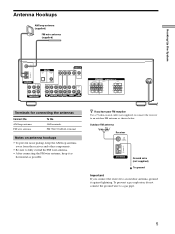
...receiver to a gas pipe. 5 To prevent a gas explosion, do not connect the ground wire to an outdoor FM antenna as possible. Hooking Up the System Antenna Hookups AM loop antenna (supplied) FM wire antenna (supplied) FM 75Ω COAXIAL AM ANTENNA ANTENNA L DIGITAL TV/SAT IN DVD/LD IN OPTICAL... pickup, keep the AM loop antenna away from the receiver and other components. • Be sure to fully extend the FM wire antenna. • After connecting the FM wire antenna, keep it against lightning. z If you connect the receiver to an outdoor antenna, ground it as horizontal as ...
...receiver to a gas pipe. 5 To prevent a gas explosion, do not connect the ground wire to an outdoor FM antenna as possible. Hooking Up the System Antenna Hookups AM loop antenna (supplied) FM wire antenna (supplied) FM 75Ω COAXIAL AM ANTENNA ANTENNA L DIGITAL TV/SAT IN DVD/LD IN OPTICAL... pickup, keep the AM loop antenna away from the receiver and other components. • Be sure to fully extend the FM wire antenna. • After connecting the FM wire antenna, keep it against lightning. z If you connect the receiver to an outdoor antenna, ground it as horizontal as ...
Operating Instructions
Page 6
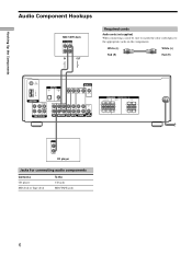
... to match the color-coded pins to the appropriate jacks on the components. White (L) White (L) Red (R) Red (R) ç FM 75Ω COAXIAL AM ANTENNA ANTENNA L DIGITAL TV/SAT IN DVD/LD IN OPTICAL CENTER L COAXIAL MONITOR VIDEO IN VIDEO IN VIDEO OUT VIDEO IN VIDEO OUT AUDIO OUT R SUB FRONT SURROUND WOOFER...
... to match the color-coded pins to the appropriate jacks on the components. White (L) White (L) Red (R) Red (R) ç FM 75Ω COAXIAL AM ANTENNA ANTENNA L DIGITAL TV/SAT IN DVD/LD IN OPTICAL CENTER L COAXIAL MONITOR VIDEO IN VIDEO IN VIDEO OUT VIDEO IN VIDEO OUT AUDIO OUT R SUB FRONT SURROUND WOOFER...
Operating Instructions
Page 7
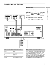
... Yellow (video) White (L/audio) Red (R/audio) Video cord for connecting a TV monitor (not supplied) Yellow Yellow FM 75Ω COAXIAL AM ANTENNA ANTENNA L DIGITAL TV/SAT IN DVD/LD IN OPTICAL CENTER L COAXIAL MONITOR VIDEO IN VIDEO IN VIDEO OUT VIDEO IN VIDEO OUT AUDIO OUT R SUB FRONT SURROUND WOOFER...monitor INPUT VIDEO IN Required cords Audio/video cords (not supplied) When connecting a cord, be sure to match the color-coded pins to the receiver as shown above. 7 If you are connecting a separate TV tuner (or satellite tuner), connect both the audio and video output jacks to the...
... Yellow (video) White (L/audio) Red (R/audio) Video cord for connecting a TV monitor (not supplied) Yellow Yellow FM 75Ω COAXIAL AM ANTENNA ANTENNA L DIGITAL TV/SAT IN DVD/LD IN OPTICAL CENTER L COAXIAL MONITOR VIDEO IN VIDEO IN VIDEO OUT VIDEO IN VIDEO OUT AUDIO OUT R SUB FRONT SURROUND WOOFER...monitor INPUT VIDEO IN Required cords Audio/video cords (not supplied) When connecting a cord, be sure to match the color-coded pins to the receiver as shown above. 7 If you are connecting a separate TV tuner (or satellite tuner), connect both the audio and video output jacks to the...
Operating Instructions
Page 8
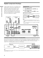
...Optical digital cords (not supplied) Black Black Coaxial digital cord (not supplied) Yellow Yellow Audio/video cords (not supplied) When connecting a cord, be sure to the receiver's digital input jacks. TUNING + SET UP - MUTING Note When making connections as the Sony MOD-RF1 (not supplied). TUNING + MEMORY SHIFT FM MODE FM... AM MENU NAME LEVEL SOUND CONTROL SURR SOUND FIELD ENTER A.F.D. You must first convert the RF signal to the receiver's COAXIAL DVD/LD IN jack...
...Optical digital cords (not supplied) Black Black Coaxial digital cord (not supplied) Yellow Yellow Audio/video cords (not supplied) When connecting a cord, be sure to the receiver's digital input jacks. TUNING + SET UP - MUTING Note When making connections as the Sony MOD-RF1 (not supplied). TUNING + MEMORY SHIFT FM MODE FM... AM MENU NAME LEVEL SOUND CONTROL SURR SOUND FIELD ENTER A.F.D. You must first convert the RF signal to the receiver's COAXIAL DVD/LD IN jack...
Operating Instructions
Page 9
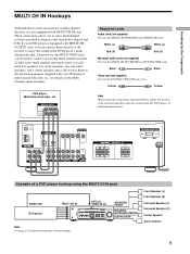
... SUB WOOFER Note See page 12 for details on speaker system hookup. Alternatively, the MULTI CH IN jacks can connect them directly to the receiver to enjoy the sound of the DVD player's multi channel decoder. Refer to the instruction manual supplied with your surround speakers and sub woofer... from the DVD player or multichannel decoder. FM 75Ω COAXIAL AM ANTENNA ANTENNA L DIGITAL TV/SAT IN DVD/LD IN OPTICAL CENTER L COAXIAL MONITOR VIDEO IN VIDEO IN VIDEO OUT VIDEO IN VIDEO OUT AUDIO OUT R SUB FRONT...
... SUB WOOFER Note See page 12 for details on speaker system hookup. Alternatively, the MULTI CH IN jacks can connect them directly to the receiver to enjoy the sound of the DVD player's multi channel decoder. Refer to the instruction manual supplied with your surround speakers and sub woofer... from the DVD player or multichannel decoder. FM 75Ω COAXIAL AM ANTENNA ANTENNA L DIGITAL TV/SAT IN DVD/LD IN OPTICAL CENTER L COAXIAL MONITOR VIDEO IN VIDEO IN VIDEO OUT VIDEO IN VIDEO OUT AUDIO OUT R SUB FRONT...
Operating Instructions
Page 10
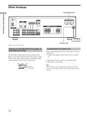
Hooking Up the Components Other Hookups VOLTAGE SELECTOR* FM 75Ω COAXIAL AM ANTENNA ANTENNA L DIGITAL TV/SAT IN DVD/LD IN OPTICAL CENTER L COAXIAL MONITOR VIDEO IN VIDEO IN VIDEO OUT ... set the selector to the correct position using a screwdriver before connecting the AC power cord to the receiver (see page 12). Connect the AC power cord(s) of area code E2, E3 only. If not... SELECTOR (models of area code E2, E3 only) Check that the voltage selector on the rear panel of this receiver to a wall outlet: • Connect the speaker system to a wall outlet. 120 V 240 V 220 V...
Hooking Up the Components Other Hookups VOLTAGE SELECTOR* FM 75Ω COAXIAL AM ANTENNA ANTENNA L DIGITAL TV/SAT IN DVD/LD IN OPTICAL CENTER L COAXIAL MONITOR VIDEO IN VIDEO IN VIDEO OUT ... set the selector to the correct position using a screwdriver before connecting the AC power cord to the receiver (see page 12). Connect the AC power cord(s) of area code E2, E3 only. If not... SELECTOR (models of area code E2, E3 only) Check that the voltage selector on the rear panel of this receiver to a wall outlet: • Connect the speaker system to a wall outlet. 120 V 240 V 220 V...
Operating Instructions
Page 12
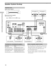
... center speaker (+) (+) (-) (-) Monaural audio cord (not supplied) One for an active woofer Black Black } }] Front speaker (R) Front speaker (L) FM 75Ω COAXIAL AM ANTENNA ANTENNA L DIGITAL TV/SAT IN DVD/LD IN OPTICAL CENTER L COAXIAL MONITOR VIDEO IN VIDEO IN VIDEO OUT VIDEO IN VIDEO OUT AUDIO OUT R SUB FRONT SURROUND WOOFER...
... center speaker (+) (+) (-) (-) Monaural audio cord (not supplied) One for an active woofer Black Black } }] Front speaker (R) Front speaker (L) FM 75Ω COAXIAL AM ANTENNA ANTENNA L DIGITAL TV/SAT IN DVD/LD IN OPTICAL CENTER L COAXIAL MONITOR VIDEO IN VIDEO IN VIDEO OUT VIDEO IN VIDEO OUT AUDIO OUT R SUB FRONT SURROUND WOOFER...
Operating Instructions
Page 23
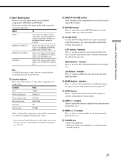
... names. PHONES jack Connects headphones. • When you connect the headphones, no digital signals, analog is selected DIGITAL (OPTICAL) Specify the digital audio signals input to the DIGITAL OPTICAL input jacks (TV/SAT only) DIGITAL (COAXIAL) Specify the digital audio signals input to the DIGITAL COAXIAL input jacks (...you selected and play the program source. • After selecting VCR, DVD player, or LD player, turn on the TV and set the receiver to output sound from the speakers. 23 w; To select Press VCR VIDEO DVD or LD player DVD/LD TV or satellite tuner TV/SAT ...
... names. PHONES jack Connects headphones. • When you connect the headphones, no digital signals, analog is selected DIGITAL (OPTICAL) Specify the digital audio signals input to the DIGITAL OPTICAL input jacks (TV/SAT only) DIGITAL (COAXIAL) Specify the digital audio signals input to the DIGITAL COAXIAL input jacks (...you selected and play the program source. • After selecting VCR, DVD player, or LD player, turn on the TV and set the receiver to output sound from the speakers. 23 w; To select Press VCR VIDEO DVD or LD player DVD/LD TV or satellite tuner TV/SAT ...
Operating Instructions
Page 44
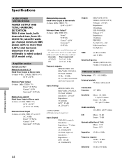
... INPUT SHORT 4) Weighted network, input level Inputs (Digital) DVD/LD (coaxial): Sensitivity: - Amplifier section POWER OUTPUT Models of area code U, CA Rated Power Output at Stereo mode (8 ohms 40 Hz - 20 kHz, THD 0.09%) 80 W + 80 W Reference Power Output (8 ohms 1 kHz, THD 0.7%) Front1): 80 W/ch Center1):...(USA model only). and high-impedance headphones TONE ±6 dB at 100 Hz and 10 kHz Sampling frequency 48 kHz (OPTICAL IN) 96 kHz (COAXIAL IN) FM tuner section Tuning range 87.5 - 108.0 MHz Antenna terminals 75 ohms, unbalanced Intermediate frequency 10.7 MHz Sensitivity Mono: 18.3...
... INPUT SHORT 4) Weighted network, input level Inputs (Digital) DVD/LD (coaxial): Sensitivity: - Amplifier section POWER OUTPUT Models of area code U, CA Rated Power Output at Stereo mode (8 ohms 40 Hz - 20 kHz, THD 0.09%) 80 W + 80 W Reference Power Output (8 ohms 1 kHz, THD 0.7%) Front1): 80 W/ch Center1):...(USA model only). and high-impedance headphones TONE ±6 dB at 100 Hz and 10 kHz Sampling frequency 48 kHz (OPTICAL IN) 96 kHz (COAXIAL IN) FM tuner section Tuning range 87.5 - 108.0 MHz Antenna terminals 75 ohms, unbalanced Intermediate frequency 10.7 MHz Sensitivity Mono: 18.3...
Service Manual
Page 1
..., 1 µV/75 ohms S/N Mono: 76 dB Stereo: 70 dB Harmonic distortion at 1 kHz Mono: 0.3% Stereo: 0.5% TONE ±6 dB at 100 Hz and 10 kHz Sampling frequency 48 kHz (OPTICAL IN) 96 kHz (COAXIAL IN) FM tuner section Tuning range 87.5 - 108.0 MHz Separation...ch 1) Depending on next page - FM STEREO FM-AM RECEIVER 9-929-587-11 2001B1600-1 © 2001.2 Sony Corporation Audio Entertainment Group General Engineering Dept. Impedance: 75 ohms S/N: 100 dB (A, 20 kHz LPF) TV/SAT (Optical): Sensitivity: - SERVICE MANUAL Ver 1.0 2001. 02 STR-DE475 US Model Canadian Model AEP Model ...
..., 1 µV/75 ohms S/N Mono: 76 dB Stereo: 70 dB Harmonic distortion at 1 kHz Mono: 0.3% Stereo: 0.5% TONE ±6 dB at 100 Hz and 10 kHz Sampling frequency 48 kHz (OPTICAL IN) 96 kHz (COAXIAL IN) FM tuner section Tuning range 87.5 - 108.0 MHz Separation...ch 1) Depending on next page - FM STEREO FM-AM RECEIVER 9-929-587-11 2001B1600-1 © 2001.2 Sony Corporation Audio Entertainment Group General Engineering Dept. Impedance: 75 ohms S/N: 100 dB (A, 20 kHz LPF) TV/SAT (Optical): Sensitivity: - SERVICE MANUAL Ver 1.0 2001. 02 STR-DE475 US Model Canadian Model AEP Model ...
Service Manual
Page 28
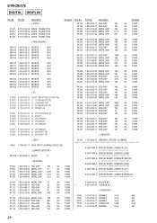
...-11 FERRITE 0UH FB1304 1-414-813-11 FERRITE 0UH FB1305 1-414-813-11 FERRITE 0UH < IC > IC1002 IC1003 IC1004 IC1005 IC1006 8-749-923-05 TORX178B(OPTICAL(TV/SAT IN)) 8-759-242-70 IC TC7WU04F(TE12R) 8-759-639-35 IC LC89055W-RA8 8-759-242-70 IC TC7WU04F(TE12R) 8-759-643-42 IC...-69 IC uPC7805AHF IC1013 8-759-039-69 IC uPC7805AHF IC1201 8-759-099-06 IC M5218AFP-TE1 IC1251 8-759-099-06 IC M5218AFP-TE1 Remarks Ref. STR-DE475 DIGITAL DISPLAY Ref.
...-11 FERRITE 0UH FB1304 1-414-813-11 FERRITE 0UH FB1305 1-414-813-11 FERRITE 0UH < IC > IC1002 IC1003 IC1004 IC1005 IC1006 8-749-923-05 TORX178B(OPTICAL(TV/SAT IN)) 8-759-242-70 IC TC7WU04F(TE12R) 8-759-639-35 IC LC89055W-RA8 8-759-242-70 IC TC7WU04F(TE12R) 8-759-643-42 IC...-69 IC uPC7805AHF IC1013 8-759-039-69 IC uPC7805AHF IC1201 8-759-099-06 IC M5218AFP-TE1 IC1251 8-759-099-06 IC M5218AFP-TE1 Remarks Ref. STR-DE475 DIGITAL DISPLAY Ref.


