
Limited Warranty (U.S. Only)
Page 1
...sale or receipted invoice which vary from your convenience, Sony Electronics Inc. Proof of purchase in material or workmanship as fuses or batteries). In addition, if you , or for all parts costs. 3. 4-557-173-02 General Stereo/Hifi Components/Tape Decks ® CD Players/Mini Disc... Players/Audio Systems Hifi Audio LIMITED WARRANTY Sony Electronics Inc. ("Sony") warrants this Product is determined to be presented to obtain warranty...
...sale or receipted invoice which vary from your convenience, Sony Electronics Inc. Proof of purchase in material or workmanship as fuses or batteries). In addition, if you , or for all parts costs. 3. 4-557-173-02 General Stereo/Hifi Components/Tape Decks ® CD Players/Mini Disc... Players/Audio Systems Hifi Audio LIMITED WARRANTY Sony Electronics Inc. ("Sony") warrants this Product is determined to be presented to obtain warranty...
Operating Instructions
Page 2
...nameplate at a large volume, the cabinet temperature of the receiver. • Do not place the receiver near heat sources, or in accordance with a mild detergent solution. STR-DE475/K402 Serial No. As an ENERGY STAR® partner, Sony Corporation has determined that the cable ground shall be sure ...of important operating and maintenance (servicing) instructions in a particular installation. If you are unable to Part 15 of the following measures: - These limits are not going to use the receiver for a long time, be connected to the grounding system of the building, as close to the...
...nameplate at a large volume, the cabinet temperature of the receiver. • Do not place the receiver near heat sources, or in accordance with a mild detergent solution. STR-DE475/K402 Serial No. As an ENERGY STAR® partner, Sony Corporation has determined that the cable ground shall be sure ...of important operating and maintenance (servicing) instructions in a particular installation. If you are unable to Part 15 of the following measures: - These limits are not going to use the receiver for a long time, be connected to the grounding system of the building, as close to the...
Operating Instructions
Page 3
...Inc. About area codes The area code of the player you purchased is shown on the receiver. • The following icon is used in this manual: z Indicates hints and tips for models STR-DE475 and STR-K402. Conventions • The instructions in this manual describe the controls on the... receiver. About This Manual The instructions in this manual are registered trademarks of Digital Theater Systems, Inc. Check your model number by looking at the lower right corner of Parts and...
...Inc. About area codes The area code of the player you purchased is shown on the receiver. • The following icon is used in this manual: z Indicates hints and tips for models STR-DE475 and STR-K402. Conventions • The instructions in this manual describe the controls on the... receiver. About This Manual The instructions in this manual are registered trademarks of Digital Theater Systems, Inc. Check your model number by looking at the lower right corner of Parts and...
Operating Instructions
Page 21
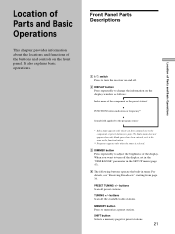
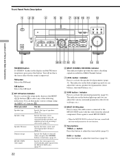
... indication or frequency** v Sound field applied to the program source * Index name appears only when you want to the component or preset station (see "Receiving Broadcasts" starting from page 34. Index name does not appear when only blank spaces have assigned one to turn the... display window as the function button. ** Frequency appears only when the tuner is the same as follows: v Index name of the display. Front Panel Parts Descriptions 1 ?/1 switch Press to turn off . 2 DISPLAY button Press repeatedly to memorize a preset station. buttons Scan all the available radio stations.
... indication or frequency** v Sound field applied to the program source * Index name appears only when you want to the component or preset station (see "Receiving Broadcasts" starting from page 34. Index name does not appear when only blank spaces have assigned one to turn the... display window as the function button. ** Frequency appears only when the tuner is the same as follows: v Index name of the display. Front Panel Parts Descriptions 1 ?/1 switch Press to turn off . 2 DISPLAY button Press repeatedly to memorize a preset station. buttons Scan all the available radio stations.
Operating Instructions
Page 22
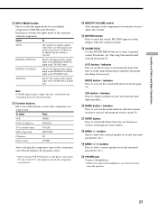
ql qk qj qh qg qf qd FM MODE button If "STEREO" flashes in the display and the FM stereo reception is decoding signals recorded in a Multi Channel format. 7 LEVEL button / indicator Press to activate the surround parameters (page 30). The indicator on the button ... to adjust the tone (treble) (page 32). MODE 2CH - BASS + VIDEO DVD/LD TV/SAT MD/TAPE CD TUNER MASTER VOLUME + - buttons (qk). Front Panel Parts Description 1 23 4 5 6 7 89 0 qa qs ? / 1 PHONES DISPLAY DIMMER MULTI CHANNEL DECODING MULTI CH IN INPUT MODE PRESET - Press again to be used with the ...
ql qk qj qh qg qf qd FM MODE button If "STEREO" flashes in the display and the FM stereo reception is decoding signals recorded in a Multi Channel format. 7 LEVEL button / indicator Press to activate the surround parameters (page 30). The indicator on the button ... to adjust the tone (treble) (page 32). MODE 2CH - BASS + VIDEO DVD/LD TV/SAT MD/TAPE CD TUNER MASTER VOLUME + - buttons (qk). Front Panel Parts Description 1 23 4 5 6 7 89 0 qa qs ? / 1 PHONES DISPLAY DIMMER MULTI CHANNEL DECODING MULTI CH IN INPUT MODE PRESET - Press again to be used with the ...
Operating Instructions
Page 23
... you selected and play the program source. • After selecting VCR, DVD player, or LD player, turn on the TV and set the receiver to select the input mode for your digital components (DVD/LD and TV/SAT). qg SOUND FIELD Use the SOUND FIELD buttons to match the... enjoy surround sound. PHONES jack Connects headphones. • When you want to adjust the selected speaker level and surround parameters (etc.). Location of Parts and Basic Operations qa INPUT MODE button Press to automatically detect the type of audio signal being input and perform proper decoding (if necessary). If...
... you selected and play the program source. • After selecting VCR, DVD player, or LD player, turn on the TV and set the receiver to select the input mode for your digital components (DVD/LD and TV/SAT). qg SOUND FIELD Use the SOUND FIELD buttons to match the... enjoy surround sound. PHONES jack Connects headphones. • When you want to adjust the selected speaker level and surround parameters (etc.). Location of Parts and Basic Operations qa INPUT MODE button Press to automatically detect the type of audio signal being input and perform proper decoding (if necessary). If...
Operating Instructions
Page 45
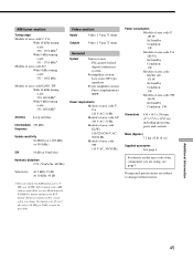
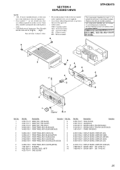
.... Additional Information 45 Hold down the TUNING + button and press the ?/1 button. To reset the scale to 9 kHz y 10 kHz. After tuning in .) including projecting parts and controls Mass (Approx.) 7.2 kg (15 lb 14 oz) Supplied accessories See page 4. AM tuner section Tuning range Models of area code U, CA With 10... area code TW 340 W In Standby Condition: 1 W Dimensions 430 × 145 × 298 mm (17 × 5 6/8 × 116/8 in any AM station, turn off the receiver.
.... Additional Information 45 Hold down the TUNING + button and press the ?/1 button. To reset the scale to 9 kHz y 10 kHz. After tuning in .) including projecting parts and controls Mass (Approx.) 7.2 kg (15 lb 14 oz) Supplied accessories See page 4. AM tuner section Tuning range Models of area code U, CA With 10... area code TW 340 W In Standby Condition: 1 W Dimensions 430 × 145 × 298 mm (17 × 5 6/8 × 116/8 in any AM station, turn off the receiver.
Service Manual
Page 2
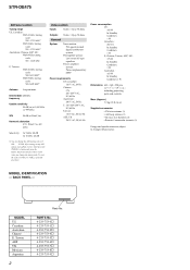
STR-DE475 AM tuner section Tuning range US, Canadian : With 10-kHz tuning scale: 530 - 1710 kHz5) With... you change the AM tuning scale to 9 kHz 10 kHz. After tuning in .) including projecting parts and controls Mass (Approx.) 7.2 kg (15 lb 14 oz) Supplied accessories • FM wire antenna (1) • AM loop antenna (1) • R6 (size-AA) batteries (2) &#...1 W Dimensions 430 × 145 × 298 mm (17 × 7 7/8 × 19 5/8 in any AM station, turn off the receiver. PARTS No. 4-233-753-0s 4-233-753-1s 4-233-753-2s 4-233-753-4s 4-233-753-5s 4-233-753-6s 4-233-753-7s 4-233-753...
STR-DE475 AM tuner section Tuning range US, Canadian : With 10-kHz tuning scale: 530 - 1710 kHz5) With... you change the AM tuning scale to 9 kHz 10 kHz. After tuning in .) including projecting parts and controls Mass (Approx.) 7.2 kg (15 lb 14 oz) Supplied accessories • FM wire antenna (1) • AM loop antenna (1) • R6 (size-AA) batteries (2) &#...1 W Dimensions 430 × 145 × 298 mm (17 × 7 7/8 × 19 5/8 in any AM station, turn off the receiver. PARTS No. 4-233-753-0s 4-233-753-1s 4-233-753-2s 4-233-753-4s 4-233-753-5s 4-233-753-6s 4-233-753-7s 4-233-753...
Service Manual
Page 3
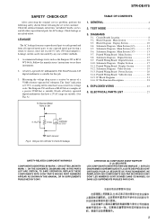
... to use these instruments. 2. REPLACE THESE COMPONENTS WITH SONY PARTS WHOSE PART NUMBERS APPEAR AS SHOWN IN THIS MANUAL OR IN SUPPLEMENTS PUBLISHED BY SONY. NE REMPLACER CES COMPOSANTS QUE PAR DES PIÈSES SONY DONT LES NUMÉROS SONT DONNÉS DANS... Pin Function Description 23 4. ELECTRICAL PARTS LIST 27 0.15 µF 1.5 kΩ AC Voltmeter (0.75 V) Earth Ground Fig. A. TEST MODE 6 3. Block Diagram Main Section 9 3-3. Schematic Diagram Main Section (2/3 12 3-6. Printed Wiring Board Video Section 20 3-15. STR-DE475 SAFETY CHECK-OUT After correcting the ...
... to use these instruments. 2. REPLACE THESE COMPONENTS WITH SONY PARTS WHOSE PART NUMBERS APPEAR AS SHOWN IN THIS MANUAL OR IN SUPPLEMENTS PUBLISHED BY SONY. NE REMPLACER CES COMPOSANTS QUE PAR DES PIÈSES SONY DONT LES NUMÉROS SONT DONNÉS DANS... Pin Function Description 23 4. ELECTRICAL PARTS LIST 27 0.15 µF 1.5 kΩ AC Voltmeter (0.75 V) Earth Ground Fig. A. TEST MODE 6 3. Block Diagram Main Section 9 3-3. Schematic Diagram Main Section (2/3 12 3-6. Printed Wiring Board Video Section 20 3-15. STR-DE475 SAFETY CHECK-OUT After correcting the ...
Service Manual
Page 7
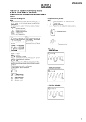
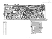
...the side which enables seeing. BE Note: The components identified by mark ! Note: Les composants identifiés par une marque ! or dotted line with part number specified. are omitted. • A : B+ Line. • B : B- sont critiques pour la sécurité. BCE These are...233;cifié. No mark : FM • Voltages are dc with a VOM (Input impedance 10 MΩ). AUS : Australian model. CH : Chinese model. DISPLAY BOARD - 2 IC102 id 63ns 5.8Vp-p - MAIN BOARD - 1 IC301 qf 230ns 2.2Vp-p - SECTION 3 DIAGRAMS STR-DE475 THIS NOTE IS COMMON FOR PRINTED...
...the side which enables seeing. BE Note: The components identified by mark ! Note: Les composants identifiés par une marque ! or dotted line with part number specified. are omitted. • A : B+ Line. • B : B- sont critiques pour la sécurité. BCE These are...233;cifié. No mark : FM • Voltages are dc with a VOM (Input impedance 10 MΩ). AUS : Australian model. CH : Chinese model. DISPLAY BOARD - 2 IC102 id 63ns 5.8Vp-p - MAIN BOARD - 1 IC301 qf 230ns 2.2Vp-p - SECTION 3 DIAGRAMS STR-DE475 THIS NOTE IS COMMON FOR PRINTED...
Service Manual
Page 14
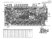
... 20) (Page 16) (Page 20) (Page 20) (Page 18) (Page 18) PHONES No. PRINTED WIRING BOARD - MAIN SECTION - • See page 8 for Circuit Boards Location. STR-DE475 There are a few cases that the part printed on this diagram isn't mounted in this model. No. No. Location Ref. Location Ref. No. Location Ref. 3-7.
... 20) (Page 16) (Page 20) (Page 20) (Page 18) (Page 18) PHONES No. PRINTED WIRING BOARD - MAIN SECTION - • See page 8 for Circuit Boards Location. STR-DE475 There are a few cases that the part printed on this diagram isn't mounted in this model. No. No. Location Ref. Location Ref. No. Location Ref. 3-7.
Service Manual
Page 16
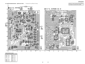
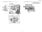
... 1006 IC 1011 • Semiconductor Location Ref. DIGITAL (Page 18) IC 1002 IC 1010 IC 1009 IC 1013 (Page 14) IC 1003 STR-DE475 There are a few cases that the part printed on this diagram isn't mounted in this model. No. No. PRINTED WIRING BOARD - 3-9. DIGITAL SECTION - • See page 8 for Circuit Boards...
... 1006 IC 1011 • Semiconductor Location Ref. DIGITAL (Page 18) IC 1002 IC 1010 IC 1009 IC 1013 (Page 14) IC 1003 STR-DE475 There are a few cases that the part printed on this diagram isn't mounted in this model. No. No. PRINTED WIRING BOARD - 3-9. DIGITAL SECTION - • See page 8 for Circuit Boards...
Service Manual
Page 18
... C-12 D101 A-6 D102 A-8 D103 C-6 D109 B-12 D110 B-12 IC101 B-13 IC102 B-7 IC103 B-10 Q008 D-12 Q009 C-5 Q100 A-8 Q101 A-7 Q103 D-3 Q104 D-3 18 18 STR-DE475 There are a few cases that the part printed on this diagram isn't mounted in this model. (Page 20) (Page 14) IC 101 (Page 14) DISPLAY SECTION - • See page...
... C-12 D101 A-6 D102 A-8 D103 C-6 D109 B-12 D110 B-12 IC101 B-13 IC102 B-7 IC103 B-10 Q008 D-12 Q009 C-5 Q100 A-8 Q101 A-7 Q103 D-3 Q104 D-3 18 18 STR-DE475 There are a few cases that the part printed on this diagram isn't mounted in this model. (Page 20) (Page 14) IC 101 (Page 14) DISPLAY SECTION - • See page...
Service Manual
Page 20
PRINTED WIRING BOARD - IC 1015 IC 1014 (Page 18) (Page 14) E model only 1-680-431- 20 20 VIDEO SECTION -• See page 8 for Circuit Boards Location. • See page 20 for Circuit Boards Location. (Page 14) (Page 14) IC 950 (Page 18) STR-DE475 3-14. POWER SECTION -• See page 8 for Schematic Diagram. PRINTED WIRING BOARD - There are a few cases that the part printed on this diagram isn't mounted in this model. 3-13.
PRINTED WIRING BOARD - IC 1015 IC 1014 (Page 18) (Page 14) E model only 1-680-431- 20 20 VIDEO SECTION -• See page 8 for Circuit Boards Location. • See page 20 for Circuit Boards Location. (Page 14) (Page 14) IC 950 (Page 18) STR-DE475 3-14. POWER SECTION -• See page 8 for Schematic Diagram. PRINTED WIRING BOARD - There are a few cases that the part printed on this diagram isn't mounted in this model. 3-13.
Service Manual
Page 25
...views are not supplied. • Accessories and packing materials are given in the last of this parts list. • Abbreviation CND: Canadian model. AR : Argentine model. MX : Mexican model. 6 STR-DE475 The components identified by mark 0 or dotted line with mark 0 are critical for routine service....portant le numéro spécifié. 6 5 #1 2 6 4 7 4 4 4 3 8 1 not supplied #2 Ref. No. 1 1 1 2 2 2 2 2 2 2 2 3 4 5 Part No. AUS : Australian model. Description Remarks 4-232-118-21 CASE (SILVER) 4-232-118-41 CASE(GOLD) 4-210-291-01 SCREW (CASE 3 TP2)(FOR BLACK) 4-210...
...views are not supplied. • Accessories and packing materials are given in the last of this parts list. • Abbreviation CND: Canadian model. AR : Argentine model. MX : Mexican model. 6 STR-DE475 The components identified by mark 0 or dotted line with mark 0 are critical for routine service....portant le numéro spécifié. 6 5 #1 2 6 4 7 4 4 4 3 8 1 not supplied #2 Ref. No. 1 1 1 2 2 2 2 2 2 2 2 3 4 5 Part No. AUS : Australian model. Description Remarks 4-232-118-21 CASE (SILVER) 4-232-118-41 CASE(GOLD) 4-210-291-01 SCREW (CASE 3 TP2)(FOR BLACK) 4-210...
Service Manual
Page 26
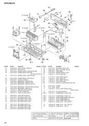
... (FLAT TYPE) (15 CORE) 3-905-609-01 SCREW (TRANSISTOR) 1-693-407-21 TUNER (US,CND,E,MX,AR) Ref. Les composants identifiés par une marque ! STR-DE475 #2 not supplied 67 66 71 #1 63 #1 55 #3 #3 not supplied T901 not supplied 70 69 not supplied #2 #1 52 72 64 #2 #1 not supplied 51 #2 #1 61 not supplied... remplacer que par une pièce portant le numéro spécifié. 26 are critical for safety. or dotted line with part number specified. No. 62 63 64 66 0 67 0 67 0 67 0 67 0 67 0 68 69 70 71 72 0 T901 1-693-408-41 4-233-753-01 4-233...
... (FLAT TYPE) (15 CORE) 3-905-609-01 SCREW (TRANSISTOR) 1-693-407-21 TUNER (US,CND,E,MX,AR) Ref. Les composants identifiés par une marque ! STR-DE475 #2 not supplied 67 66 71 #1 63 #1 55 #3 #3 not supplied T901 not supplied 70 69 not supplied #2 #1 52 72 64 #2 #1 not supplied 51 #2 #1 61 not supplied... remplacer que par une pièce portant le numéro spécifié. 26 are critical for safety. or dotted line with part number specified. No. 62 63 64 66 0 67 0 67 0 67 0 67 0 67 0 68 69 70 71 72 0 T901 1-693-408-41 4-233-753-01 4-233...
Service Manual
Page 27
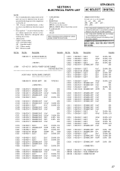
... set. • -XX, -X mean standardized parts, so they may be anticipated when ordering these items. • Abbreviation CND: Canadian model. Description Remarks Ref. Part No. AUS : Australian model. Part No. CH : Chinese model. The components identified...;PB... , uPC... , µPC... , uPD..., µPD... SECTION 5 ELECTRICAL PARTS LIST STR-DE475 AC SELECT DIGITAL NOTE: • Due to standardization, replacements in the parts list may have some difference from the parts specified in ohms. METAL: metal-film resistor METAL OXIDE: Metal Oxide-film resistor F: nonflammable...
... set. • -XX, -X mean standardized parts, so they may be anticipated when ordering these items. • Abbreviation CND: Canadian model. Description Remarks Ref. Part No. AUS : Australian model. Part No. CH : Chinese model. The components identified...;PB... , uPC... , µPC... , uPD..., µPD... SECTION 5 ELECTRICAL PARTS LIST STR-DE475 AC SELECT DIGITAL NOTE: • Due to standardization, replacements in the parts list may have some difference from the parts specified in ohms. METAL: metal-film resistor METAL OXIDE: Metal Oxide-film resistor F: nonflammable...
Service Manual
Page 28
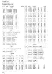
... 5.5V R1117 1-216-025-11 RES-CHIP 100 5% 1/10W C103 1-164-159-21 CERAMIC 0.1uF 50V R1118 1-216-025-11 RES-CHIP 100 5% 1/10W 28 Part No. No. No. Description < DIODE > D1101 D1201 D1202 D1301 8-719-016-74 8-719-016-74 8-719-016-74 8-719-016-74 DIODE DIODE DIODE DIODE...-69 IC uPC7805AHF IC1013 8-759-039-69 IC uPC7805AHF IC1201 8-759-099-06 IC M5218AFP-TE1 IC1251 8-759-099-06 IC M5218AFP-TE1 Remarks Ref. Part No. STR-DE475 DIGITAL DISPLAY Ref.
... 5.5V R1117 1-216-025-11 RES-CHIP 100 5% 1/10W C103 1-164-159-21 CERAMIC 0.1uF 50V R1118 1-216-025-11 RES-CHIP 100 5% 1/10W 28 Part No. No. No. Description < DIODE > D1101 D1201 D1202 D1301 8-719-016-74 8-719-016-74 8-719-016-74 8-719-016-74 DIODE DIODE DIODE DIODE...-69 IC uPC7805AHF IC1013 8-759-039-69 IC uPC7805AHF IC1201 8-759-099-06 IC M5218AFP-TE1 IC1251 8-759-099-06 IC M5218AFP-TE1 Remarks Ref. Part No. STR-DE475 DIGITAL DISPLAY Ref.
Service Manual
Page 29
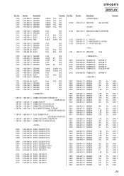
.... C104 C105 C106 C107 C108 Part No. STR-DE475 DISPLAY Ref. Description 1-127-880-31 CERAMIC 1-127-880-31 CERAMIC 1-127-880-31 CERAMIC 1-127-880-31 CERAMIC 1-127-880-31 CERAMIC 0.022uF 10% 0....
.... C104 C105 C106 C107 C108 Part No. STR-DE475 DISPLAY Ref. Description 1-127-880-31 CERAMIC 1-127-880-31 CERAMIC 1-127-880-31 CERAMIC 1-127-880-31 CERAMIC 1-127-880-31 CERAMIC 0.022uF 10% 0....
Service Manual
Page 30
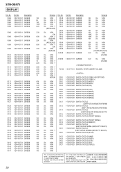
... 5% 1/4W 5% 1/4W 5% 1/4W 5% 1/4W 5% 1/4W 5% 1/4W 5% 1/4W 5% 1/4W 5% 1/4W 5% 1/4W 5% 1/4W 5% 1/4W 5% 1/4W 5% 1/4W F 5% 1/4W 5% 1/4W 5% 1/4W 5% 1/4W 5% 1/4W 5% 1/4W 5% 1/4W 5% 1/4W 5% 1/4W Ref. STR-DE475 DISPLAY Ref. R148 R149 R150 R151 R152 R153 R154 R161 R162 R163 R164 R165 R187 R188 0 R198 0 R199 RV102 S100 S101 S102 S103 S104 S105... S106 S107 S110 S111 S112 S113 S114 S115 S116 S117 S118 S120 S121 S122 S123 S124 S125 S126 S127 Part No. R058 R062 R064 R065 R098 Part No. Description 1-247-807-31 CARBON 100 1-247-807-31 CARBON 100 1-247-807-31 CARBON 100 1-247-807-...
... 5% 1/4W 5% 1/4W 5% 1/4W 5% 1/4W 5% 1/4W 5% 1/4W 5% 1/4W 5% 1/4W 5% 1/4W 5% 1/4W 5% 1/4W 5% 1/4W 5% 1/4W 5% 1/4W F 5% 1/4W 5% 1/4W 5% 1/4W 5% 1/4W 5% 1/4W 5% 1/4W 5% 1/4W 5% 1/4W 5% 1/4W Ref. STR-DE475 DISPLAY Ref. R148 R149 R150 R151 R152 R153 R154 R161 R162 R163 R164 R165 R187 R188 0 R198 0 R199 RV102 S100 S101 S102 S103 S104 S105... S106 S107 S110 S111 S112 S113 S114 S115 S116 S117 S118 S120 S121 S122 S123 S124 S125 S126 S127 Part No. R058 R062 R064 R065 R098 Part No. Description 1-247-807-31 CARBON 100 1-247-807-31 CARBON 100 1-247-807-31 CARBON 100 1-247-807-...


