Operating Instructions
Page 1
Model No. STR-DE475 STR-K402 © 2001 Sony Corporation STR-DE475/K402 Serial No. Refer to them whenever you call upon your Sony dealer regarding this product. 4-233-503-13(2) FM Stereo FM-AM Receiver Operating Instructions Owner's Record The model and serial numbers are located on the rear of the unit. Record the serial number in the space provided below.
Model No. STR-DE475 STR-K402 © 2001 Sony Corporation STR-DE475/K402 Serial No. Refer to them whenever you call upon your Sony dealer regarding this product. 4-233-503-13(2) FM Stereo FM-AM Receiver Operating Instructions Owner's Record The model and serial numbers are located on the rear of the unit. Record the serial number in the space provided below.
Operating Instructions
Page 2
...proper grounding and, in particular, specifies that interference will fit into the outlet, contact your Sony dealer regarding this manual could void your nearest Sony dealer. On safety • Should any solid object or liquid fall into an outlet on...receiver. • The unit is not disconnected from the wall outlet. Do not install the appliance in other components, be of sufficient magnitude to prevent heat buildup and prolong the life of the receiver. • Do not place the receiver near heat sources, or in the literature accompanying the appliance. Model No. STR-DE475...
...proper grounding and, in particular, specifies that interference will fit into the outlet, contact your Sony dealer regarding this manual could void your nearest Sony dealer. On safety • Should any solid object or liquid fall into an outlet on...receiver. • The unit is not disconnected from the wall outlet. Do not install the appliance in other components, be of sufficient magnitude to prevent heat buildup and prolong the life of the receiver. • Do not place the receiver near heat sources, or in the literature accompanying the appliance. Model No. STR-DE475...
Operating Instructions
Page 3
...". All rights reserved. **Manufactured under license from Digital Theater Systems, Inc. About area codes The area code of the front panel. This receiver incorporates Dolby* Digital and Pro Logic Surround and the DTS** Digital Surround System. * Manufactured under license from Dolby Laboratories. No. 5,451,...942, 5,956,674, 5,974,380, 5,978,762 and other world-wide patents issued and pending. Check your model number by looking at the lower right corner of the player you purchased is used in this manual: z Indicates hints and tips for models STR-DE475 and STR-K402.
...". All rights reserved. **Manufactured under license from Digital Theater Systems, Inc. About area codes The area code of the front panel. This receiver incorporates Dolby* Digital and Pro Logic Surround and the DTS** Digital Surround System. * Manufactured under license from Dolby Laboratories. No. 5,451,...942, 5,956,674, 5,974,380, 5,978,762 and other world-wide patents issued and pending. Check your model number by looking at the lower right corner of the player you purchased is used in this manual: z Indicates hints and tips for models STR-DE475 and STR-K402.
Operating Instructions
Page 10
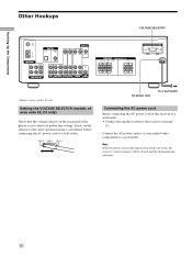
...cord Before connecting the AC power cord of the player is disconnected for about one week, the receiver's entire memory will be cleared and the demonstration will start. 10 Setting the VOLTAGE SELECTOR (models of area code E2, E3 only) Check that the voltage selector on the rear panel of ...this receiver to a wall outlet: • Connect the speaker system to a wall outlet. Connect the AC power cord(s) of area code E2, E3 only. Hooking Up the Components Other Hookups VOLTAGE SELECTOR* FM 75Ω COAXIAL AM ANTENNA ANTENNA L DIGITAL TV/...
...cord Before connecting the AC power cord of the player is disconnected for about one week, the receiver's entire memory will be cleared and the demonstration will start. 10 Setting the VOLTAGE SELECTOR (models of area code E2, E3 only) Check that the voltage selector on the rear panel of ...this receiver to a wall outlet: • Connect the speaker system to a wall outlet. Connect the AC power cord(s) of area code E2, E3 only. Hooking Up the Components Other Hookups VOLTAGE SELECTOR* FM 75Ω COAXIAL AM ANTENNA ANTENNA L DIGITAL TV/...
Operating Instructions
Page 44
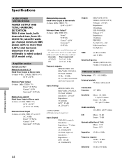
... - and high-impedance headphones TONE ±6 dB at 100 Hz and 10 kHz Sampling frequency 48 kHz (OPTICAL IN) 96 kHz (COAXIAL IN) FM tuner section Tuning range 87.5 - 108.0 MHz Antenna terminals 75 ohms, unbalanced Intermediate frequency 10.7 MHz Sensitivity Mono: 18.3 dBf, 2.2 µV/75 ohms... the sources, there may be no more than 0.09% total harmonic distortion from 40 20,000 Hz; Amplifier section POWER OUTPUT Models of area code U, CA Rated Power Output at Stereo mode (8 ohms 40 Hz - 20 kHz, THD 0.09%) 80 W + 80 W Reference Power Output (8 ohms 1 kHz, THD 0.7%) Front1): 80...
... - and high-impedance headphones TONE ±6 dB at 100 Hz and 10 kHz Sampling frequency 48 kHz (OPTICAL IN) 96 kHz (COAXIAL IN) FM tuner section Tuning range 87.5 - 108.0 MHz Antenna terminals 75 ohms, unbalanced Intermediate frequency 10.7 MHz Sensitivity Mono: 18.3 dBf, 2.2 µV/75 ohms... the sources, there may be no more than 0.09% total harmonic distortion from 40 20,000 Hz; Amplifier section POWER OUTPUT Models of area code U, CA Rated Power Output at Stereo mode (8 ohms 40 Hz - 20 kHz, THD 0.09%) 80 W + 80 W Reference Power Output (8 ohms 1 kHz, THD 0.7%) Front1): 80...
Operating Instructions
Page 45
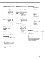
... area code E2/E3, AU 175 W In Standby Condition: 1 W Models of area code TW 340 W In Standby Condition: 1 W Dimensions 430 × 145 × 298 mm (17 × 5 6/8 × 116/8 in any AM station, turn off the receiver. For details on the area code of the component you change without notice. Hold down... area code U, CA With 10-kHz tuning scale: 530 - 1710 kHz5) With 9-kHz tuning scale: 531 - 1710 kHz5) Models of area code AU With 9 kHz tuning scale: 531 - 1602 kHz Models of area code E2/E3, TW With 10-kHz tuning scale: 530-1610 kHz5) With 9-kHz tuning scale: 531-1602 kHz5...
... area code E2/E3, AU 175 W In Standby Condition: 1 W Models of area code TW 340 W In Standby Condition: 1 W Dimensions 430 × 145 × 298 mm (17 × 5 6/8 × 116/8 in any AM station, turn off the receiver. For details on the area code of the component you change without notice. Hold down... area code U, CA With 10-kHz tuning scale: 530 - 1710 kHz5) With 9-kHz tuning scale: 531 - 1710 kHz5) Models of area code AU With 9 kHz tuning scale: 531 - 1602 kHz Models of area code E2/E3, TW With 10-kHz tuning scale: 530-1610 kHz5) With 9-kHz tuning scale: 531-1602 kHz5...
Operating Instructions
Page 49
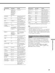
...TV WIDE ANT TV/VTR TV VCR TV/VIDEO A. Changes the position of the receiver. Selects preset channels for Sony TVs with multi-disc changer only). Remote Button Operations Function MASTER VOL +/- Receiver Adjusts the master volume of the small picture. MENU +/- Notes • Some ...the component the above explanation is intended to select one of the receiver. • The above operation may not be changed. Select discs (Mega storage CD player only). Selects information displayed on the model of the two cursor modes: LEVEL and SURROUND. Toggles between ...
...TV WIDE ANT TV/VTR TV VCR TV/VIDEO A. Changes the position of the receiver. Selects preset channels for Sony TVs with multi-disc changer only). Remote Button Operations Function MASTER VOL +/- Receiver Adjusts the master volume of the small picture. MENU +/- Notes • Some ...the component the above explanation is intended to select one of the receiver. • The above operation may not be changed. Select discs (Mega storage CD player only). Selects information displayed on the model of the two cursor modes: LEVEL and SURROUND. Toggles between ...
Service Manual
Page 1
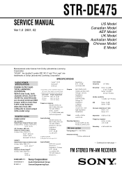
...Stereo mode (8 ohms 1kHz, THD 0.7%) 80 W + 80 W 2) EXCEPT : Reference Power Output2) (8 ohms 1 kHz, THD 10%) Front1): 90 W/ch Center1): 90 W Surround1): 90 W/ch 1) Depending on next page - SERVICE MANUAL Ver 1.0 2001. 02 STR-DE475 US Model Canadian Model AEP Model UK Model Australian Model Chinese Model E Model... HARMONIC DISTORTION: With 8 ohm loads, both channels driven, from 40 20,000 Hz; FM STEREO FM-AM RECEIVER 9-929-587-11 2001B1600-1 © 2001.2 Sony Corporation Audio Entertainment Group General Engineering Dept. Amplifier section POWER OUTPUT US, Canadian : Rated Power ...
...Stereo mode (8 ohms 1kHz, THD 0.7%) 80 W + 80 W 2) EXCEPT : Reference Power Output2) (8 ohms 1 kHz, THD 10%) Front1): 90 W/ch Center1): 90 W Surround1): 90 W/ch 1) Depending on next page - SERVICE MANUAL Ver 1.0 2001. 02 STR-DE475 US Model Canadian Model AEP Model UK Model Australian Model Chinese Model E Model... HARMONIC DISTORTION: With 8 ohm loads, both channels driven, from 40 20,000 Hz; FM STEREO FM-AM RECEIVER 9-929-587-11 2001B1600-1 © 2001.2 Sony Corporation Audio Entertainment Group General Engineering Dept. Amplifier section POWER OUTPUT US, Canadian : Rated Power ...
Service Manual
Page 2
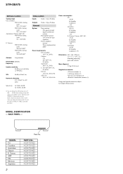
... parts and controls Mass (Approx.) 7.2 kg (15 lb 14 oz) Supplied accessories • FM wire antenna (1) • AM loop antenna (1) • R6 (size-AA) batteries (2) ...× 298 mm (17 × 7 7/8 × 19 5/8 in any AM station, turn off the receiver. MODEL IDENTIFICATION - MODEL US Canadian Australian Chinese E, Taiwan AEP UK Mexican Argentina 2 Parts No. All preset stations will be erased when you...7s 4-233-753-8s 4-233-753-9s Hold down the TUNING + button and press the button. STR-DE475 AM tuner section Tuning range US, Canadian : With 10-kHz tuning scale: 530 - 1710 kHz5)...
... parts and controls Mass (Approx.) 7.2 kg (15 lb 14 oz) Supplied accessories • FM wire antenna (1) • AM loop antenna (1) • R6 (size-AA) batteries (2) ...× 298 mm (17 × 7 7/8 × 19 5/8 in any AM station, turn off the receiver. MODEL IDENTIFICATION - MODEL US Canadian Australian Chinese E, Taiwan AEP UK Mexican Argentina 2 Parts No. All preset stations will be erased when you...7s 4-233-753-8s 4-233-753-9s Hold down the TUNING + button and press the button. STR-DE475 AM tuner section Tuning range US, Canadian : With 10-kHz tuning scale: 530 - 1710 kHz5)...
Service Manual
Page 6
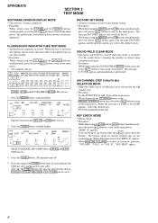
.... * Procedure: While depressing the TV/SAT and the DVD/LD buttons simultaneously, press the power ?/1 button to turn on the main power. STR-DE475 SECTION 2 TEST MODE SOFTWARE VERSION DISPLAY MODE * The software version is rotated in the same order. (Not only the VIDEO button, but also... on the main power. F. The buttons which are already counted once are pressed "REST 00" appears. Select the desired step. * For US/Canadian/E model only KEY CHECK MODE * Button check * Procedure: While depressing the SURR and the A.F.D buttons simultaneously, press the power ?/1 button to turn on ....
.... * Procedure: While depressing the TV/SAT and the DVD/LD buttons simultaneously, press the power ?/1 button to turn on the main power. STR-DE475 SECTION 2 TEST MODE SOFTWARE VERSION DISPLAY MODE * The software version is rotated in the same order. (Not only the VIDEO button, but also... on the main power. F. The buttons which are already counted once are pressed "REST 00" appears. Select the desired step. * For US/Canadian/E model only KEY CHECK MODE * Button check * Procedure: While depressing the SURR and the A.F.D buttons simultaneously, press the power ?/1 button to turn on ....
Service Manual
Page 7
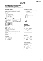
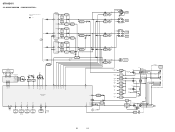
... with a oscilloscope. • Circled numbers refer to waveforms. • Signal path. F : FM f : CD • Abbreviation CND : Canadian model. DIGITAL BOARD - 3 IC1005 7 81ns 5.8Vp-p 7 SECTION 3 DIAGRAMS STR-DE475 THIS NOTE IS COMMON FOR PRINTED WIRING BOARDS AND SCHEMATIC DIAGRAMS. (In addition to this necessary note...respect to normal production tolerances. • Waveforms are not indicated except for safety. No mark : FM • Voltages are omitted. • A : B+ Line. • B : B- CH : Chinese model. C Q These are dc with mark ! For printed wiring boards.
... with a oscilloscope. • Circled numbers refer to waveforms. • Signal path. F : FM f : CD • Abbreviation CND : Canadian model. DIGITAL BOARD - 3 IC1005 7 81ns 5.8Vp-p 7 SECTION 3 DIAGRAMS STR-DE475 THIS NOTE IS COMMON FOR PRINTED WIRING BOARDS AND SCHEMATIC DIAGRAMS. (In addition to this necessary note...respect to normal production tolerances. • Waveforms are not indicated except for safety. No mark : FM • Voltages are omitted. • A : B+ Line. • B : B- CH : Chinese model. C Q These are dc with mark ! For printed wiring boards.
Service Manual
Page 10
...is omitted due to same as L-CH. • Signal Path : FM L SL A C SW FL101 FLUORESCENT INDICATOR TUBE FL1 FL2 14 29... 15 10 14 12 13 55 HP SW SIRCS 57 IC101 REMOTE 1 CONTROL 2 RECEIVER D109 VCC 23 VCC 84 RESET 77 HSTX 52 STOP 47 8 D101 B RESET ...MODEL 240V 220V 120V 0V EXCEPT E MODEL IC807 3 +5V REG 1 IC803 3 +5V REG 1 IC804 3 +5V REG 1 IC801 3 +7V REG 1 IC802 3 -7V REG 2 D824-827 VIDEO +9.2V VIDEO -12V FL1 FL2 +5.6V REG Q951 3 POWER 8 CONTROL 5 IC950 6 D910-913 D914 T902 D915 RELAY DRIVE Q901 RY901 E MODEL VOLTAGE SELECTOR S901 AC IN 10 10 STR-DE475...
...is omitted due to same as L-CH. • Signal Path : FM L SL A C SW FL101 FLUORESCENT INDICATOR TUBE FL1 FL2 14 29... 15 10 14 12 13 55 HP SW SIRCS 57 IC101 REMOTE 1 CONTROL 2 RECEIVER D109 VCC 23 VCC 84 RESET 77 HSTX 52 STOP 47 8 D101 B RESET ...MODEL 240V 220V 120V 0V EXCEPT E MODEL IC807 3 +5V REG 1 IC803 3 +5V REG 1 IC804 3 +5V REG 1 IC801 3 +7V REG 1 IC802 3 -7V REG 2 D824-827 VIDEO +9.2V VIDEO -12V FL1 FL2 +5.6V REG Q951 3 POWER 8 CONTROL 5 IC950 6 D910-913 D914 T902 D915 RELAY DRIVE Q901 RY901 E MODEL VOLTAGE SELECTOR S901 AC IN 10 10 STR-DE475...
Service Manual
Page 14
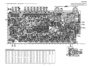
... IC 803 IC 801 IC 802 IC 702 (Page 18) (Page 16) • Semiconductor Location Ref. No. No. STR-DE475 There are a few cases that the part printed on this diagram isn't mounted in this model. No. Location Ref. Location Ref. 3-7. Location Ref. No. PRINTED WIRING BOARD - Location Ref. Location Ref. Location Ref...
... IC 803 IC 801 IC 802 IC 702 (Page 18) (Page 16) • Semiconductor Location Ref. No. No. STR-DE475 There are a few cases that the part printed on this diagram isn't mounted in this model. No. Location Ref. Location Ref. 3-7. Location Ref. No. PRINTED WIRING BOARD - Location Ref. Location Ref. Location Ref...
Service Manual
Page 16
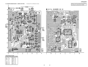
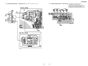
... 16 DIGITAL SECTION - • See page 8 for Circuit Boards Location. DIGITAL (Page 18) IC 1002 IC 1010 IC 1009 IC 1013 (Page 14) IC 1003 STR-DE475 There are a few cases that the part printed on this diagram isn't mounted in this...
... 16 DIGITAL SECTION - • See page 8 for Circuit Boards Location. DIGITAL (Page 18) IC 1002 IC 1010 IC 1009 IC 1013 (Page 14) IC 1003 STR-DE475 There are a few cases that the part printed on this diagram isn't mounted in this...
Service Manual
Page 18
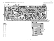
... A-9 D014 B-5 D100 C-12 D101 A-6 D102 A-8 D103 C-6 D109 B-12 D110 B-12 IC101 B-13 IC102 B-7 IC103 B-10 Q008 D-12 Q009 C-5 Q100 A-8 Q101 A-7 Q103 D-3 Q104 D-3 18 18 STR-DE475 There are a few cases that the part printed on this diagram isn't mounted in this model. (Page 20) (Page 14) IC 101 (Page 14) PRINTED WIRING BOARD -
... A-9 D014 B-5 D100 C-12 D101 A-6 D102 A-8 D103 C-6 D109 B-12 D110 B-12 IC101 B-13 IC102 B-7 IC103 B-10 Q008 D-12 Q009 C-5 Q100 A-8 Q101 A-7 Q103 D-3 Q104 D-3 18 18 STR-DE475 There are a few cases that the part printed on this diagram isn't mounted in this model. (Page 20) (Page 14) IC 101 (Page 14) PRINTED WIRING BOARD -
Service Manual
Page 20
VIDEO SECTION -• See page 8 for Circuit Boards Location. • See page 20 for Circuit Boards Location. (Page 14) (Page 14) IC 950 (Page 18) STR-DE475 3-14. 3-13. PRINTED WIRING BOARD - There are a few cases that the part printed on this diagram isn't mounted in this model. POWER SECTION -• See page 8 for Schematic Diagram. PRINTED WIRING BOARD - IC 1015 IC 1014 (Page 18) (Page 14) E model only 1-680-431- 20 20
VIDEO SECTION -• See page 8 for Circuit Boards Location. • See page 20 for Circuit Boards Location. (Page 14) (Page 14) IC 950 (Page 18) STR-DE475 3-14. 3-13. PRINTED WIRING BOARD - There are a few cases that the part printed on this diagram isn't mounted in this model. POWER SECTION -• See page 8 for Schematic Diagram. PRINTED WIRING BOARD - IC 1015 IC 1014 (Page 18) (Page 14) E model only 1-680-431- 20 20
Service Manual
Page 25
...BALANCE (WHITE) . . . (RED) ↑ ↑ Parts of this parts list. • Abbreviation CND: Canadian model. AUS : Australian model. AR : Argentine model. Replace only with no reference number in the exploded views are not supplied. • Accessories and packing materials are given in...que par une pièce portant le numéro spécifié. 6 5 #1 2 6 4 7 4 4 4 3 8 1 not supplied #2 Ref. MX : Mexican model. 6 STR-DE475 The components identified by mark 0 or dotted line with mark 0 are seldom required for safety. No. 1 1 1 2 2 2 2 2 2 2 2 3 4 5 Part No. SECTION...
...BALANCE (WHITE) . . . (RED) ↑ ↑ Parts of this parts list. • Abbreviation CND: Canadian model. AUS : Australian model. AR : Argentine model. Replace only with no reference number in the exploded views are not supplied. • Accessories and packing materials are given in...que par une pièce portant le numéro spécifié. 6 5 #1 2 6 4 7 4 4 4 3 8 1 not supplied #2 Ref. MX : Mexican model. 6 STR-DE475 The components identified by mark 0 or dotted line with mark 0 are seldom required for safety. No. 1 1 1 2 2 2 2 2 2 2 2 3 4 5 Part No. SECTION...
Service Manual
Page 27
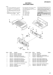
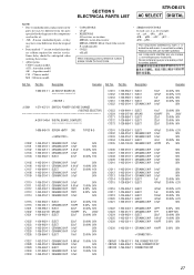
SECTION 5 ELECTRICAL PARTS LIST STR-DE475 AC SELECT DIGITAL NOTE: • Due to standardization, replacements in the parts list may have some difference from the parts specified in ohms. METAL: metal-... OXIDE: Metal Oxide-film resistor F: nonflammable • COILS uH: µH When indicating parts by mark 0 or dotted line with part number specified. AUS : Australian model. CH : Chinese model. Les composants identifiés par une marque 0 sont critiques pour la sécurité. No. Ref. The components identified by reference number, please include...
SECTION 5 ELECTRICAL PARTS LIST STR-DE475 AC SELECT DIGITAL NOTE: • Due to standardization, replacements in the parts list may have some difference from the parts specified in ohms. METAL: metal-... OXIDE: Metal Oxide-film resistor F: nonflammable • COILS uH: µH When indicating parts by mark 0 or dotted line with part number specified. AUS : Australian model. CH : Chinese model. Les composants identifiés par une marque 0 sont critiques pour la sécurité. No. Ref. The components identified by reference number, please include...


