
Limited Warranty (U.S. Only)
Page 1
...Services Center 1-800-222-7669 or visit the Sony Web Site: www.sony.com For an accessory or part not available from state to state. SONY SHALL NOT BE LIABLE FOR ANY INCIDENTAL OR CONSEQUENTIAL DAMAGES FOR BREACH OF ANY EXPRESS OR IMPLIED WARRANTY ON THIS PRODUCT. This warranty does not cover customer instruction, installation, set up adjustments or signal reception problems... telephone numbers for one (1) year. 4-557-173-02 General Stereo/Hifi Components/Tape Decks ® CD Players/Mini Disc Players/Audio Systems Hifi Audio LIMITED WARRANTY Sony Electronics Inc. ("Sony") warrants...
...Services Center 1-800-222-7669 or visit the Sony Web Site: www.sony.com For an accessory or part not available from state to state. SONY SHALL NOT BE LIABLE FOR ANY INCIDENTAL OR CONSEQUENTIAL DAMAGES FOR BREACH OF ANY EXPRESS OR IMPLIED WARRANTY ON THIS PRODUCT. This warranty does not cover customer instruction, installation, set up adjustments or signal reception problems... telephone numbers for one (1) year. 4-557-173-02 General Stereo/Hifi Components/Tape Decks ® CD Players/Mini Disc Players/Audio Systems Hifi Audio LIMITED WARRANTY Sony Electronics Inc. ("Sony") warrants...
Operating Instructions (Receiver Component)
Page 2
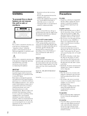
... presence of the cabinet that the cable ground shall be sure to radio communications. STR-DE535/STR-DE435/ STR-SE491 Serial No On power sources • Before operating the receiver, check that may cause harmful interference to disconnect the receiver from the AC power source (MAINS) as long as it any type of important operating and maintenance (servicing) instructions in a residential installation. Increase the separation between the...
... presence of the cabinet that the cable ground shall be sure to radio communications. STR-DE535/STR-DE435/ STR-SE491 Serial No On power sources • Before operating the receiver, check that may cause harmful interference to disconnect the receiver from the AC power source (MAINS) as long as it any type of important operating and maintenance (servicing) instructions in a residential installation. Increase the separation between the...
Operating Instructions (Receiver Component)
Page 3
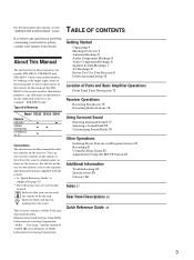
... Adjustments Using the SET UP button 23 Additional Information Troubleshooting 24 Specifications 25 Glossary 26 Index 27 Rear Panel Descriptions 28 Quick Reference Guide 29 3 TABLE OF CONTENTS If you can also use of your remote, refer to do the task. Check your nearest Sony dealer. Manufactured under license from Dolby Laboratories Licensing Corporation. Getting Started Unpacking 4 Hookup Overview 4 Antenna Hookups 5 Audio Component Hookups 5 Video Component Hookups 6 Speaker System Hookups 7 AC Hookups 9 Before You Use Your Receiver 9 Dolby Surround Setup...
... Adjustments Using the SET UP button 23 Additional Information Troubleshooting 24 Specifications 25 Glossary 26 Index 27 Rear Panel Descriptions 28 Quick Reference Guide 29 3 TABLE OF CONTENTS If you can also use of your remote, refer to do the task. Check your nearest Sony dealer. Manufactured under license from Dolby Laboratories Licensing Corporation. Getting Started Unpacking 4 Hookup Overview 4 Antenna Hookups 5 Audio Component Hookups 5 Video Component Hookups 6 Speaker System Hookups 7 AC Hookups 9 Before You Use Your Receiver 9 Dolby Surround Setup...
Operating Instructions (Receiver Component)
Page 4
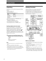
... the operating instructions supplied with your remote. Speaker System Hookups (7) Video Component Hookups (6) TV monitor DVD player/ AC-3 decoder (except STRSE491) Antenna Hookups (5) TV tuner AM/FM antenna Front speaker (L) SAT (Satellite receiver) VCR Front speaker (R) Rear speaker (L) CD player Center speaker MD/Tape deck Turntable (except STR- White (left, audio) to connect and control the following buttons on the receiver. When using the remote, point it at the remote sensor (STR-DE535) or g (STR-DE435 and STR-SE491) on the RM-PP402 remote (STR-DE435 and STR-SE491...
... the operating instructions supplied with your remote. Speaker System Hookups (7) Video Component Hookups (6) TV monitor DVD player/ AC-3 decoder (except STRSE491) Antenna Hookups (5) TV tuner AM/FM antenna Front speaker (L) SAT (Satellite receiver) VCR Front speaker (R) Rear speaker (L) CD player Center speaker MD/Tape deck Turntable (except STR- White (left, audio) to connect and control the following buttons on the receiver. When using the remote, point it at the remote sensor (STR-DE535) or g (STR-DE435 and STR-SE491) on the RM-PP402 remote (STR-DE435 and STR-SE491...
Operating Instructions (Receiver Component)
Page 5
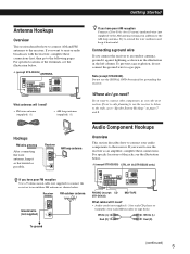
... loop antenna. Note (except STR-DE435) Do not use the receiver as shown below. Audio Component Hookups Overview This section describes how to connect your audio components to the receiver. If you have poor FM reception Use a 75-ohm coaxial cable (not supplied) to connect the receiver to use the SIGNAL GND y terminal for each MD recorder or tape deck) White (L) Red (R) White (L) Red (R) (continued) 5 Try to a gas pipe. Where do not connect the ground wire to...
... loop antenna. Note (except STR-DE435) Do not use the receiver as shown below. Audio Component Hookups Overview This section describes how to connect your audio components to the receiver. If you have poor FM reception Use a 75-ohm coaxial cable (not supplied) to connect the receiver to use the SIGNAL GND y terminal for each MD recorder or tape deck) White (L) Red (R) White (L) Red (R) (continued) 5 Try to a gas pipe. Where do not connect the ground wire to...
Operating Instructions (Receiver Component)
Page 6
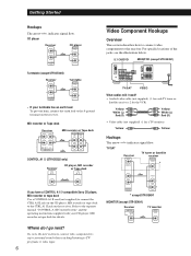
For specific locations of the jacks, see the illustration below. 5.1 CH/DVD MONITOR (except STR-SE491) TV/SAT VIDEO What cables will I go next? Video Component Hookups Overview This section describes how to connect video components to TV programs or video tapes. 6 Getting Started Hookups The arrow ç indicates signal flow. Refer to the separate manual "CONTROL-A1 II Control System" and the operating instructions supplied with your turntable has an earth lead To...
For specific locations of the jacks, see the illustration below. 5.1 CH/DVD MONITOR (except STR-SE491) TV/SAT VIDEO What cables will I go next? Video Component Hookups Overview This section describes how to connect video components to TV programs or video tapes. 6 Getting Started Hookups The arrow ç indicates signal flow. Refer to the separate manual "CONTROL-A1 II Control System" and the operating instructions supplied with your turntable has an earth lead To...

Operating Instructions (Receiver Component)
Page 7
... the amplifier. To enjoy surround effects, center and rear speakers and an active woofer are reversed, the sound will be distorted and will I go next? Go on the components: + to the receiver. Receiver FRONT 5.1 CH/DVD REAR CENTER L R WOOFER VIDEO IN Dolby Digital AC-3 decoder, etc. Getting Started VCR Receiver VIDEO OUT VIDEO IN VCR OUTPUT INPUT VIDEO VIDEO L R AUDIO OUT AUDIO IN VIDEO AUDIO AUDIO L R * except STR-SE491 Use the function buttons (TV/SAT, CD, MD/TAPE etc.) to connect the speakers. (continued) 7 Hookups Front speakers Front speaker (R) Receiver...
... the amplifier. To enjoy surround effects, center and rear speakers and an active woofer are reversed, the sound will be distorted and will I go next? Go on the components: + to the receiver. Receiver FRONT 5.1 CH/DVD REAR CENTER L R WOOFER VIDEO IN Dolby Digital AC-3 decoder, etc. Getting Started VCR Receiver VIDEO OUT VIDEO IN VCR OUTPUT INPUT VIDEO VIDEO L R AUDIO OUT AUDIO IN VIDEO AUDIO AUDIO L R * except STR-SE491 Use the function buttons (TV/SAT, CD, MD/TAPE etc.) to connect the speakers. (continued) 7 Hookups Front speakers Front speaker (R) Receiver...

Operating Instructions (Receiver Component)
Page 8
... speakers with Dolby Pro Logic Surround sound (see page 12). Where do I go to connect a second active woofer. To complete your TV monitor uses separate speakers You can connect the active woofer to the SPEAKERS FRONT B terminals. Check the instruction manual of your speaker is touching another speaker cord. If no sound is heard from a speaker while outputting a test tone or a test tone is output from the left and right rear speakers. Active woofer * STR-DE535 only Receiver WOOFER AUDIO OUT Active woofer INPUT STR-DE435 and STR...
... speakers with Dolby Pro Logic Surround sound (see page 12). Where do I go to connect a second active woofer. To complete your TV monitor uses separate speakers You can connect the active woofer to the SPEAKERS FRONT B terminals. Check the instruction manual of your speaker is touching another speaker cord. If no sound is heard from a speaker while outputting a test tone or a test tone is output from the left and right rear speakers. Active woofer * STR-DE535 only Receiver WOOFER AUDIO OUT Active woofer INPUT STR-DE435 and STR...
Operating Instructions (Receiver Component)
Page 9
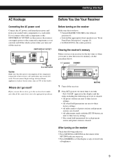
... DIMMER to set the display at any of four levels of preset stations and program sources) are cleared. • All adjustments made with the SET UP button are set to the center position. After turning on the receiver Check the following are reset or cleared: • All preset stations are reset to their factory settings. • All sound field parameters are reset to a wall outlet Caution Make sure that you use your audio/video components to...
... DIMMER to set the display at any of four levels of preset stations and program sources) are cleared. • All adjustments made with the SET UP button are set to the center position. After turning on the receiver Check the following are reset or cleared: • All preset stations are reset to their factory settings. • All sound field parameters are reset to a wall outlet Caution Make sure that you use your audio/video components to...

Operating Instructions (Receiver Component)
Page 10
Locating the speakers For optimum Dolby Pro Logic Surround sound, locate your front speakers The center channel fully reproduces the entire audio spectrum Adjusting the speaker volume The test tone feature lets you can reproduce highly precise localization and dynamic panning of sounds of speakers and/or a center speaker. Each mode is designed for TV programs and movies. repeatedly to adjust the speaker volume.) Using the controls on the remote, you set (see next page) from wherever you...
Locating the speakers For optimum Dolby Pro Logic Surround sound, locate your front speakers The center channel fully reproduces the entire audio spectrum Adjusting the speaker volume The test tone feature lets you can reproduce highly precise localization and dynamic panning of sounds of speakers and/or a center speaker. Each mode is designed for TV programs and movies. repeatedly to adjust the speaker volume.) Using the controls on the remote, you set (see next page) from wherever you...

Operating Instructions (Receiver Component)
Page 11
... 3 STEREO mode is selected The test tone is preset from the front L (left speakers, use the BALANCE control on the remote. • To adjust the volume level of the center speaker, press the LEVEL CENTER +/- Getting Started 5 Adjust the volume level so that is produced by 5dB The adjustment range of the rear speakers is output from -15 to + 10, but you can adjust the volume level of the test tone for sound fields other than PRO LOGIC. 11 Front (L) Front (R) Center Increasing the output level...
... 3 STEREO mode is selected The test tone is preset from the front L (left speakers, use the BALANCE control on the remote. • To adjust the volume level of the center speaker, press the LEVEL CENTER +/- Getting Started 5 Adjust the volume level so that is produced by 5dB The adjustment range of the rear speakers is output from -15 to + 10, but you can adjust the volume level of the test tone for sound fields other than PRO LOGIC. 11 Front (L) Front (R) Center Increasing the output level...
Operating Instructions (Receiver Component)
Page 12
.../DVD jacks. The 5.1 CH/DVD indicator lights up when the sound is turned on. To listen to or watch Press Video tapes VIDEO TV programs or Satellite receiver TV/SAT MiniDiscs or audio tapes MD/TAPE Compact discs (CD) CD Radio programs TUNER Records PHONO (except STR-DE435) DVD player/AC-3 decoder 5.1 CH/DVD After selecting the component, turn on the component you selected and play the program source. 4 65 3 5.1 CH/DVD button Press to select the component connected to turn on and off. To select Speakers connected to the SPEAKERS FRONT A terminals Speakers connected...
.../DVD jacks. The 5.1 CH/DVD indicator lights up when the sound is turned on. To listen to or watch Press Video tapes VIDEO TV programs or Satellite receiver TV/SAT MiniDiscs or audio tapes MD/TAPE Compact discs (CD) CD Radio programs TUNER Records PHONO (except STR-DE435) DVD player/AC-3 decoder 5.1 CH/DVD After selecting the component, turn on the component you selected and play the program source. 4 65 3 5.1 CH/DVD button Press to select the component connected to turn on and off. To select Speakers connected to the SPEAKERS FRONT A terminals Speakers connected...
Operating Instructions (Receiver Component)
Page 13
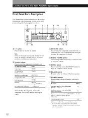
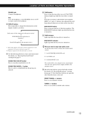
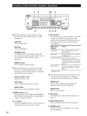
... tuner. BASS BOOST button Press to scan all preset stations. TUNING +/- Note To use the headphones, set the SPEAKERS selector to OFF to output sound to the headphones. 8 DISPLAY button Press repeatedly to change the information on . PRESET TUNING +/- The TONE indicator lights up while the bass boost is turned on the display window as follows: v Index name of Parts and Basic Amplifier Operations PHONES jack Connects headphones. buttons Press to the program source. !™ The following buttons to the component...
... tuner. BASS BOOST button Press to scan all preset stations. TUNING +/- Note To use the headphones, set the SPEAKERS selector to OFF to output sound to the headphones. 8 DISPLAY button Press repeatedly to change the information on . PRESET TUNING +/- The TONE indicator lights up while the bass boost is turned on the display window as follows: v Index name of Parts and Basic Amplifier Operations PHONES jack Connects headphones. buttons Press to the program source. !™ The following buttons to the component...
Operating Instructions (Receiver Component)
Page 14
... CTR MODE Select any one of the four center modes (page 10) REAR GAIN Increase the range of rear speakers by 5 dB (page 11) AUTO FUNCTION* Specify whether or not Sony components connected via Control A1 II cables will turn on or off response to remote signals sent from the 2 way remote. (page 23) * STR-DE535 only. !• Press the following buttons operate the built-in the display and the FM stereo reception is selected. When...
... CTR MODE Select any one of the four center modes (page 10) REAR GAIN Increase the range of rear speakers by 5 dB (page 11) AUTO FUNCTION* Specify whether or not Sony components connected via Control A1 II cables will turn on or off response to remote signals sent from the 2 way remote. (page 23) * STR-DE535 only. !• Press the following buttons operate the built-in the display and the FM stereo reception is selected. When...
Operating Instructions (Receiver Component)
Page 19
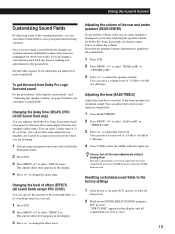
... select "EFFECT xx." Changing the delay time (DELAY) (PRO LOGIC Sound Field only) You can select a delay time of 15, 20, or 30 ms. Set a short delay time when the rear speakers are located in 2-dB steps. 1 Start playing a program source encoded with Dolby Surround sound. 2 Press SUR. 3 Press MENU to change the delay time. Adjusting the tone (BASS/TREBLE) Adjust the tone (bass or treble) of -15 dB to suit your particular listening situation. Press the TONE button to adjust the volume. You can turn off the tone adjustments...
... select "EFFECT xx." Changing the delay time (DELAY) (PRO LOGIC Sound Field only) You can select a delay time of 15, 20, or 30 ms. Set a short delay time when the rear speakers are located in 2-dB steps. 1 Start playing a program source encoded with Dolby Surround sound. 2 Press SUR. 3 Press MENU to change the delay time. Adjusting the tone (BASS/TREBLE) Adjust the tone (bass or treble) of -15 dB to suit your particular listening situation. Press the TONE button to adjust the volume. You can turn off the tone adjustments...
Operating Instructions (Receiver Component)
Page 22
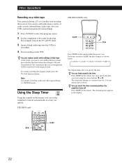
... only STR-DE435/SE491 only SLEEP >/. Other Operations Recording on a video tape You can record from a variety of audio sources when editing a video tape. See your VCR's instruction manual if you want using the receiver. SLEEP 22 You can replace audio while editing a video tape At the point you need help. 1 Press TV/SAT to select the program source. 2 Set the component to 5 hours. For example, turn off Press SLEEP on the remote. The sleep time changes...
... only STR-DE435/SE491 only SLEEP >/. Other Operations Recording on a video tape You can record from a variety of audio sources when editing a video tape. See your VCR's instruction manual if you want using the receiver. SLEEP 22 You can replace audio while editing a video tape At the point you need help. 1 Press TV/SAT to select the program source. 2 Set the component to 5 hours. For example, turn off Press SLEEP on the remote. The sleep time changes...
Operating Instructions (Receiver Component)
Page 24
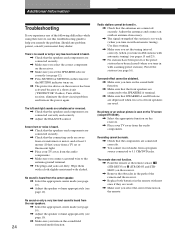
... low-level sound is heard. / Check that SPEAKERS A and B buttons are depressed when two sets of front speakers are connected correctly. / You cannot record audio from a transformer or motor, and at the remote sensor (STR-DE535) or g (STR-DE435 and STRSE491) on the power again. Adjust the antennas and connect an outdoor antenna if necessary. / The signal strength of the remote and the receiver. / Replace both batteries in the remote with automatic tuning). Should...
... low-level sound is heard. / Check that SPEAKERS A and B buttons are depressed when two sets of front speakers are connected correctly. / You cannot record audio from a transformer or motor, and at the remote sensor (STR-DE535) or g (STR-DE435 and STRSE491) on the power again. Adjust the antennas and connect an outdoor antenna if necessary. / The signal strength of the remote and the receiver. / Replace both batteries in the remote with automatic tuning). Should...
Operating Instructions (Receiver Component)
Page 25
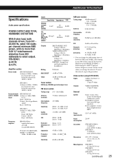
Hold down the PRESET TUNING + button and press the 1/u (power) button. All preset stations will be erased when you change the AM tuning interval between 9 kHz and 10 kHz. Video section (except STR-SE491) Inputs VIDEO, TV/SAT, 5.1 CH/DVD: 1 Vp-p 75 ohms Outputs VIDEO, MONITOR: 1 Vp-p 75 ohms General System Power requirements Power consumption AC outlets Dimensions Tuner section: PLL quartz-locked digital synthesizer system Preamplifier section: Low-noise NF type equalizer Power amplifier section: Pure-complementary...
Hold down the PRESET TUNING + button and press the 1/u (power) button. All preset stations will be erased when you change the AM tuning interval between 9 kHz and 10 kHz. Video section (except STR-SE491) Inputs VIDEO, TV/SAT, 5.1 CH/DVD: 1 Vp-p 75 ohms Outputs VIDEO, MONITOR: 1 Vp-p 75 ohms General System Power requirements Power consumption AC outlets Dimensions Tuner section: PLL quartz-locked digital synthesizer system Preamplifier section: Low-noise NF type equalizer Power amplifier section: Pure-complementary...

Operating Instructions (Receiver Component)
Page 26
... sound • Transition of the rear channel is output from rear speakers Direct sound Early Level reflections Reverberation Rear Rear speaker (L) speaker (R) • WIDE mode Select WIDE mode if you hear the sound affect the way these jacks to connect a Dolby Digital (AC-3) decoder or a DVD player with an expanded frequency range and a subwoofer channel for movie theaters is more precisely. Front speaker (L) Front speaker (R) Delay time Time lag between the surround sound output from the fact that is stored in memory of rear speakers and a center speaker. Make the delay time...
... sound • Transition of the rear channel is output from rear speakers Direct sound Early Level reflections Reverberation Rear Rear speaker (L) speaker (R) • WIDE mode Select WIDE mode if you hear the sound affect the way these jacks to connect a Dolby Digital (AC-3) decoder or a DVD player with an expanded frequency range and a subwoofer channel for movie theaters is more precisely. Front speaker (L) Front speaker (R) Delay time Time lag between the surround sound output from the fact that is stored in memory of rear speakers and a center speaker. Make the delay time...
Operating Instructions (Receiver Component)
Page 27
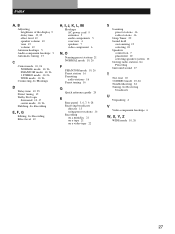
... 10, 26 PHANTOM mode 10, 26 3 STEREO mode 10, 26 WIDE mode 10, 26 Connecting. See Hookups D Delay time 19, 25 Direct tuning 15 Dolby Pro Logic Surround 10, 17 center mode 10, 26 Dubbing. See Receiving broadcasts U Unpacking 4 V Video component hookups 6 W, X, Y, Z WIDE mode 10, 26 27 See Recording E, F, G Editing. See Recording Effect level 19 H, I, J, K, L, M Hookups AC power cord 9 antennas 5 audio components 5 overview 4 speakers 7 video component 6 N, O Naming preset stations 21 NORMAL mode 10, 26 P PHANTOM mode 10, 26 Preset station 16 Presetting radio stations 16 Preset tuning 16...
... 10, 26 PHANTOM mode 10, 26 3 STEREO mode 10, 26 WIDE mode 10, 26 Connecting. See Hookups D Delay time 19, 25 Direct tuning 15 Dolby Pro Logic Surround 10, 17 center mode 10, 26 Dubbing. See Receiving broadcasts U Unpacking 4 V Video component hookups 6 W, X, Y, Z WIDE mode 10, 26 27 See Recording E, F, G Editing. See Recording Effect level 19 H, I, J, K, L, M Hookups AC power cord 9 antennas 5 audio components 5 overview 4 speakers 7 video component 6 N, O Naming preset stations 21 NORMAL mode 10, 26 P PHANTOM mode 10, 26 Preset station 16 Presetting radio stations 16 Preset tuning 16...


