Operating Instructions
Page 1
4-229-127-13(1) FM Stereo FM-AM Receiver Operating Instructions STR-DB940 STR-DB840 © 2000 Sony Corporation
4-229-127-13(1) FM Stereo FM-AM Receiver Operating Instructions STR-DB940 STR-DB840 © 2000 Sony Corporation
Operating Instructions
Page 2
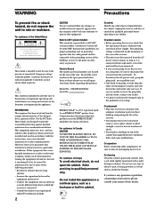
... the cable ground shall be determined by turning the equipment off and on, the user is a U.S. STR-DB940/DB840 Serial No. On power sources • Before operating the receiver, check that the operating voltage is intended to alert the user to Article 82040 of important operating and ... The model and serial numbers are not going to use any further. As an ENERGY STAR® partner, Sony Corporation has determined that interference will fit into the cabinet, unplug the receiver and have any changes or modification not expressly approved in this manual could void your...
... the cable ground shall be determined by turning the equipment off and on, the user is a U.S. STR-DB940/DB840 Serial No. On power sources • Before operating the receiver, check that the operating voltage is intended to alert the user to Article 82040 of important operating and ... The model and serial numbers are not going to use any further. As an ENERGY STAR® partner, Sony Corporation has determined that interference will fit into the cabinet, unplug the receiver and have any changes or modification not expressly approved in this manual could void your...
Operating Instructions
Page 3
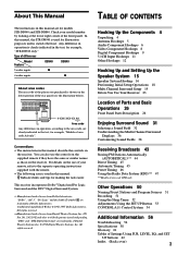
...Enjoying Surround Sound 31 Selecting a Sound Field 32 Understanding the Multi-Channel Surround Displays 36 Customizing Sound Fields 38 Receiving Broadcasts 43 Storing FM Stations Automatically (AUTOBETICAL)*** 44 Direct Tuning 45 Automatic Tuning 45 Preset Tuning 46 Using the Radio Data System ... manual: z Indicates hints and tips for making the task easier. This receiver incorporates Dolby* Digital and Pro Logic Surround and the DTS** Digital Surround System. * Manufactured under license from Dolby Laboratories. Any difference in operation is used for models STR-DB940 and STR-DB840.
...Enjoying Surround Sound 31 Selecting a Sound Field 32 Understanding the Multi-Channel Surround Displays 36 Customizing Sound Fields 38 Receiving Broadcasts 43 Storing FM Stations Automatically (AUTOBETICAL)*** 44 Direct Tuning 45 Automatic Tuning 45 Preset Tuning 46 Using the Radio Data System ... manual: z Indicates hints and tips for making the task easier. This receiver incorporates Dolby* Digital and Pro Logic Surround and the DTS** Digital Surround System. * Manufactured under license from Dolby Laboratories. Any difference in operation is used for models STR-DB940 and STR-DB840.
Operating Instructions
Page 4
...: • FM wire antenna (1) • AM loop antenna (1) Models of area code U, CA only • Audio/video/control S connecting cord (1) • Control S connecting cord (1) STR-DB940 only • Remote commander RM-LJ304 (remote) (1) • LR6 (size-AA) alkaline batteries (3) STR-DB840 only •... Models of area code CED only - Notes • Do not leave the remote in the battery compartment. Before you get started • Turn off the power to all components before you actually connect them to the receiver. 4 Unpacking Check that...
...: • FM wire antenna (1) • AM loop antenna (1) Models of area code U, CA only • Audio/video/control S connecting cord (1) • Control S connecting cord (1) STR-DB940 only • Remote commander RM-LJ304 (remote) (1) • LR6 (size-AA) alkaline batteries (3) STR-DB840 only •... Models of area code CED only - Notes • Do not leave the remote in the battery compartment. Before you get started • Turn off the power to all components before you actually connect them to the receiver. 4 Unpacking Check that...
Operating Instructions
Page 5
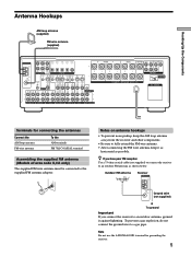
...PHONO CD MD/DAT TAPE TV/SAT DVD/LD VIDEO 2 VIDEO 1 R 2ND AUDIO OUT Terminals for grounding the receiver. 5 Hooking Up the Components Antenna Hookups AM loop antenna (supplied) FM wire antenna (supplied) ANTENNA AM L MD/DAT MD/DAT TV/SAT DVD/LD DVD/LD OPTICAL OPTICAL OPTICAL ... OUT VIDEO S-VIDEO S-VIDEO IN IN VIDEO VIDEO OUT VIDEO IN VIDEO S-VIDEO S-VIDEO OUT IN VIDEO VIDEO R - z If you connect the receiver to the supplied FM antenna adaptor. FM COA7X5IΩAL Notes on antenna hookups • To prevent noise pickup, keep the AM loop antenna away from the...
...PHONO CD MD/DAT TAPE TV/SAT DVD/LD VIDEO 2 VIDEO 1 R 2ND AUDIO OUT Terminals for grounding the receiver. 5 Hooking Up the Components Antenna Hookups AM loop antenna (supplied) FM wire antenna (supplied) ANTENNA AM L MD/DAT MD/DAT TV/SAT DVD/LD DVD/LD OPTICAL OPTICAL OPTICAL ... OUT VIDEO S-VIDEO S-VIDEO IN IN VIDEO VIDEO OUT VIDEO IN VIDEO S-VIDEO S-VIDEO OUT IN VIDEO VIDEO R - z If you connect the receiver to the supplied FM antenna adaptor. FM COA7X5IΩAL Notes on antenna hookups • To prevent noise pickup, keep the AM loop antenna away from the...
Operating Instructions
Page 6
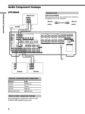
Hooking Up the Components Audio Component Hookups STR-DB940 MD/DAT deck INPUT OUTPUT LINE LINE L R ç ç Turntable OUT ...jacks Note on audio component hookups If your turntable has a ground wire, connect it to the appropriate jacks on the receiver. 6 White (L) White (L) Red (R) Red (R) ANTENNA AM L MD/DAT MD/DAT TV/SAT DVD/LD DVD.../LD OPTICAL OPTICAL OPTICAL OPTICAL COAXIAL OUT IN IN IN IN CENTER B + U FM 75Ω COAXIAL R FRONT REAR SUB WOOFER 5.1CH INPUT CTRL S IN CTRL S STATUS IN DIGITAL CTRL S OUT CTRL S OUT...
Hooking Up the Components Audio Component Hookups STR-DB940 MD/DAT deck INPUT OUTPUT LINE LINE L R ç ç Turntable OUT ...jacks Note on audio component hookups If your turntable has a ground wire, connect it to the appropriate jacks on the receiver. 6 White (L) White (L) Red (R) Red (R) ANTENNA AM L MD/DAT MD/DAT TV/SAT DVD/LD DVD.../LD OPTICAL OPTICAL OPTICAL OPTICAL COAXIAL OUT IN IN IN IN CENTER B + U FM 75Ω COAXIAL R FRONT REAR SUB WOOFER 5.1CH INPUT CTRL S IN CTRL S STATUS IN DIGITAL CTRL S OUT CTRL S OUT...
Operating Instructions
Page 7
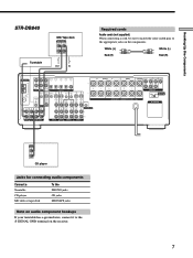
Hooking Up the Components ç STR-DB840 Turntable MD/Tape deck INPUT OUTPUT LINE LINE L R ç OUT IN Required cords... jacks Note on audio component hookups If your turntable has a ground wire, connect it to the appropriate jacks on the receiver. 7 White (L) White (L) Red (R) Red (R) ANTENNA AM L MD/TAPE MD/TAPE TV/SAT DVD/LD DVD.../LD OPTICAL OPTICAL OPTICAL OPTICAL COAXIAL OUT IN IN IN IN CENTER B + U FM 75Ω COAXIAL R FRONT REAR SUB WOOFER 5.1CH INPUT CTRL S IN CTRL S STATUS IN DIGITAL CTRL S OUT CTRL S OUT...
Hooking Up the Components ç STR-DB840 Turntable MD/Tape deck INPUT OUTPUT LINE LINE L R ç OUT IN Required cords... jacks Note on audio component hookups If your turntable has a ground wire, connect it to the appropriate jacks on the receiver. 7 White (L) White (L) Red (R) Red (R) ANTENNA AM L MD/TAPE MD/TAPE TV/SAT DVD/LD DVD.../LD OPTICAL OPTICAL OPTICAL OPTICAL COAXIAL OUT IN IN IN IN CENTER B + U FM 75Ω COAXIAL R FRONT REAR SUB WOOFER 5.1CH INPUT CTRL S IN CTRL S STATUS IN DIGITAL CTRL S OUT CTRL S OUT...
Operating Instructions
Page 8
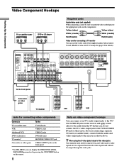
...jacks MONITOR VIDEO OUT jack VIDEO 3 INPUT jacks on the front panel 1) For STR-DB940, you are on the receiver and apply sound effects to the audio from the video signals and will not be... a separate TV tuner (or satellite tuner), connect both the audio and video output jacks to the receiver as shown above. Ç Ç Hooking Up the Components Video Component Hookups TV or satellite tuner...TV/SAT DVD/LD DVD/LD OPTICAL OPTICAL OPTICAL OPTICAL COAXIAL OUT IN IN IN IN CENTER B + U FM 75Ω COAXIAL R FRONT REAR SUB WOOFER 5.1CH INPUT CTRL S IN CTRL S STATUS IN DIGITAL ...
...jacks MONITOR VIDEO OUT jack VIDEO 3 INPUT jacks on the front panel 1) For STR-DB940, you are on the receiver and apply sound effects to the audio from the video signals and will not be... a separate TV tuner (or satellite tuner), connect both the audio and video output jacks to the receiver as shown above. Ç Ç Hooking Up the Components Video Component Hookups TV or satellite tuner...TV/SAT DVD/LD DVD/LD OPTICAL OPTICAL OPTICAL OPTICAL COAXIAL OUT IN IN IN IN CENTER B + U FM 75Ω COAXIAL R FRONT REAR SUB WOOFER 5.1CH INPUT CTRL S IN CTRL S STATUS IN DIGITAL ...
Operating Instructions
Page 9
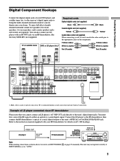
...MD/DAT TV/SAT DVD/LD DVD/LD OPTICAL OPTICAL OPTICAL OPTICAL COAXIAL OUT IN IN IN IN CENTER B + U FM 75Ω COAXIAL R FRONT REAR SUB WOOFER 5.1CH INPUT CTRL S IN CTRL S STATUS IN DIGITAL CTRL S OUT...jack. Refer to "AUTO." 9 Example of LD player connected via an RF demodulator, like the Sony MOD-RF1 (not supplied). This unit may not operate correctly if INPUT MODE is set INPUT MODE ...Connect the digital output jacks of your DVD player and satellite tuner (etc.) to the receiver's digital input jacks to set to the instruction manual supplied with an RF OUT jack ...
...MD/DAT TV/SAT DVD/LD DVD/LD OPTICAL OPTICAL OPTICAL OPTICAL COAXIAL OUT IN IN IN IN CENTER B + U FM 75Ω COAXIAL R FRONT REAR SUB WOOFER 5.1CH INPUT CTRL S IN CTRL S STATUS IN DIGITAL CTRL S OUT...jack. Refer to "AUTO." 9 Example of LD player connected via an RF demodulator, like the Sony MOD-RF1 (not supplied). This unit may not operate correctly if INPUT MODE is set INPUT MODE ...Connect the digital output jacks of your DVD player and satellite tuner (etc.) to the receiver's digital input jacks to set to the instruction manual supplied with an RF OUT jack ...

Operating Instructions
Page 10
... OUT IN ANTENNA AM L MD/DAT MD/DAT TV/SAT DVD/LD DVD/LD OPTICAL OPTICAL OPTICAL OPTICAL COAXIAL OUT IN IN IN IN CENTER B + U FM 75Ω COAXIAL R FRONT REAR SUB WOOFER 5.1CH INPUT CTRL S IN CTRL S STATUS IN DIGITAL CTRL S OUT CTRL S OUT SIGNAL GND U S-VIDEO OUT VIDEO ... you cannot make a digital recording of a digital multi channel surround signal. • To make digital recordings of your MD or DAT deck to the receiver's digital output jack. Refer to the instructions supplied with your CD player and MD or DAT deck for details. • The DVD/LD IN OPTICAL...
... OUT IN ANTENNA AM L MD/DAT MD/DAT TV/SAT DVD/LD DVD/LD OPTICAL OPTICAL OPTICAL OPTICAL COAXIAL OUT IN IN IN IN CENTER B + U FM 75Ω COAXIAL R FRONT REAR SUB WOOFER 5.1CH INPUT CTRL S IN CTRL S STATUS IN DIGITAL CTRL S OUT CTRL S OUT SIGNAL GND U S-VIDEO OUT VIDEO ... you cannot make a digital recording of a digital multi channel surround signal. • To make digital recordings of your MD or DAT deck to the receiver's digital output jack. Refer to the instructions supplied with your CD player and MD or DAT deck for details. • The DVD/LD IN OPTICAL...
Operating Instructions
Page 11
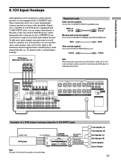
... jacks VIDEO OUT DVD player 5.1 CH INPUT ?/1 DVD/LD IN VIDEO etc. Alternatively, the 5.1CH INPUT jacks can connect them directly to this receiver incorporates a multi channel decoder, it is equipped with your DVD player, multi channel decoder, etc., for details on the 5.1 channel input hookups. These... decoder. ANTENNA AM L MD/DAT MD/DAT TV/SAT DVD/LD DVD/LD OPTICAL OPTICAL OPTICAL OPTICAL COAXIAL OUT IN IN IN IN CENTER B + U FM 75Ω COAXIAL R FRONT REAR SUB WOOFER 5.1CH INPUT CTRL S IN CTRL S STATUS IN DIGITAL CTRL S OUT CTRL S OUT SIGNAL GND U S-...
... jacks VIDEO OUT DVD player 5.1 CH INPUT ?/1 DVD/LD IN VIDEO etc. Alternatively, the 5.1CH INPUT jacks can connect them directly to this receiver incorporates a multi channel decoder, it is equipped with your DVD player, multi channel decoder, etc., for details on the 5.1 channel input hookups. These... decoder. ANTENNA AM L MD/DAT MD/DAT TV/SAT DVD/LD DVD/LD OPTICAL OPTICAL OPTICAL OPTICAL COAXIAL OUT IN IN IN IN CENTER B + U FM 75Ω COAXIAL R FRONT REAR SUB WOOFER 5.1CH INPUT CTRL S IN CTRL S STATUS IN DIGITAL CTRL S OUT CTRL S OUT SIGNAL GND U S-...
Operating Instructions
Page 12
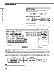
...2 VIDEO 1 R 2ND AUDIO OUT 2ND AUDIO OUT (STR-DB940 only) b To a wall outlet * The configuration,...outlets on the rear panel varies according to the model and country to which the receiver is selected. 12 White (L) White (L) Red (R) Red (R) Audio/video/control S... OUT IN IN IN IN CENTER B + U FM 75Ω COAXIAL R FRONT REAR SUB WOOFER 5....AUDIO AUDIO 2 8 OUT IN R Speaker (L) - + - + 1 0 • • • 9 10 Stereo amplifier SPEAKERS •• • • - + - + L Speaker (R) Note This function is not available when 5....
...2 VIDEO 1 R 2ND AUDIO OUT 2ND AUDIO OUT (STR-DB940 only) b To a wall outlet * The configuration,...outlets on the rear panel varies according to the model and country to which the receiver is selected. 12 White (L) White (L) Red (R) Red (R) Audio/video/control S... OUT IN IN IN IN CENTER B + U FM 75Ω COAXIAL R FRONT REAR SUB WOOFER 5....AUDIO AUDIO 2 8 OUT IN R Speaker (L) - + - + 1 0 • • • 9 10 Stereo amplifier SPEAKERS •• • • - + - + L Speaker (R) Note This function is not available when 5....

Operating Instructions
Page 13
...supplied audio/video/control S cable for connection A.) ** Control S connecting cord Note Refer to the CONTROL A1 jack on the receiver. If, however, you have a Sony CD changer with a COMMAND MODE selector If your CD player, tape deck, or MD deck for details. The following connections ...also change to TV whenever you turn on the receiver. When your TV, satellite tuner, monitor, VCR, etc., for details regarding the operations you have a S-LINK CONTROL S-compatible Sony TV, satellite tuner, monitor, DVD player or VCR, use an audio/video/control...
...supplied audio/video/control S cable for connection A.) ** Control S connecting cord Note Refer to the CONTROL A1 jack on the receiver. If, however, you have a Sony CD changer with a COMMAND MODE selector If your CD player, tape deck, or MD deck for details. The following connections ...also change to TV whenever you turn on the receiver. When your TV, satellite tuner, monitor, VCR, etc., for details regarding the operations you have a S-LINK CONTROL S-compatible Sony TV, satellite tuner, monitor, DVD player or VCR, use an audio/video/control...
Operating Instructions
Page 14
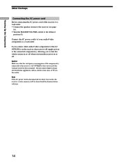
If you connect other audio/video components to the AC OUTLET(s) on the receiver, the receiver will start. 14 Hooking Up the Components Other Hookups Connecting the AC power cord Before connecting the AC power cord of your audio/video components ... appliances such as electric irons, fans, or TVs to the leftmost position (0). Note If the AC power cord is disconnected for about two weeks, the receiver's entire memory will be cleared and the demonstration will supply power to the connected component(s), allowing you to the...
If you connect other audio/video components to the AC OUTLET(s) on the receiver, the receiver will start. 14 Hooking Up the Components Other Hookups Connecting the AC power cord Before connecting the AC power cord of your audio/video components ... appliances such as electric irons, fans, or TVs to the leftmost position (0). Note If the AC power cord is disconnected for about two weeks, the receiver's entire memory will be cleared and the demonstration will supply power to the connected component(s), allowing you to the...

Operating Instructions
Page 15
...; • • 6• • 3 7 2 8 1 0 • • • 9 10 Jog dial Brief descriptions of each speaker, and how to set up your speaker system to the receiver, how to select parameters after pressing the SET UP button. Jog dial: Use to adjust the setting of buttons and control used to set up...
...; • • 6• • 3 7 2 8 1 0 • • • 9 10 Jog dial Brief descriptions of each speaker, and how to set up your speaker system to the receiver, how to select parameters after pressing the SET UP button. Jog dial: Use to adjust the setting of buttons and control used to set up...

Operating Instructions
Page 17
... of 8 ohms or higher if you 're not sure of 8 ohms or higher, and set the speaker IMPEDANCE SELECTOR to "4Ω". For details on the receiver, the speaker may damage the...
... of 8 ohms or higher if you 're not sure of 8 ohms or higher, and set the speaker IMPEDANCE SELECTOR to "4Ω". For details on the receiver, the speaker may damage the...
Operating Instructions
Page 18
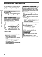
..."Now Demonstration Mode!! This procedure is not necessary if the demonstration activates when you turn the receiver on the power, clear the receiver's memory. Performing initial setup operations Before using your receiver for your system. You can adjust the following . The next time you turn the power on... or off automatically via the CONTROL A1 control system (page 53). • Whether the display turns off or not when you press DIMMER (page 54). • STR-DB940 only:...
..."Now Demonstration Mode!! This procedure is not necessary if the demonstration activates when you turn the receiver on the power, clear the receiver's memory. Performing initial setup operations Before using your receiver for your system. You can adjust the following . The next time you turn the power on... or off automatically via the CONTROL A1 control system (page 53). • Whether the display turns off or not when you press DIMMER (page 54). • STR-DB940 only:...
Operating Instructions
Page 19
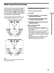
... the same distance from the listening position (A). Normally, select "LARGE". • If the sound is distorted, or you or to the side, depending on the receiver. 2 Press SET UP. 3 Press the cursor buttons ( or ) to select the parameter you want to adjust. 4 Turn the jog dial to your room (etc.). Hooking...
... the same distance from the listening position (A). Normally, select "LARGE". • If the sound is distorted, or you or to the side, depending on the receiver. 2 Press SET UP. 3 Press the cursor buttons ( or ) to select the parameter you want to adjust. 4 Turn the jog dial to your room (etc.). Hooking...

Operating Instructions
Page 22
... test tone from 60 Hz to turn off the test tone. z You can be output when the receiver is not conducive to "SMALL". on the remote. 4 Press TEST TONE again to turn on the receiver. 2 Press TEST TONE on the front panel (except for setting distances. 1 foot corresponds to input the speaker...
... test tone from 60 Hz to turn off the test tone. z You can be output when the receiver is not conducive to "SMALL". on the remote. 4 Press TEST TONE again to turn on the receiver. 2 Press TEST TONE on the front panel (except for setting distances. 1 foot corresponds to input the speaker...
Operating Instructions
Page 23
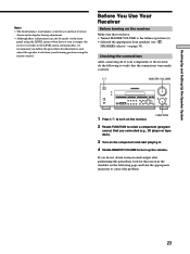
... following to verify that the connections were made via the front panel using the LEVEL menu (when the test tone is output, the receiver switches to the LEVEL menu automatically), we recommend you do the following page and take the appropriate measures to correct the problem. 23 ...Checking the connections After connecting all of your components to the receiver, do not obtain normal sound output after performing this procedure, look for the reason in the display during adjustment. • Although these ...
... following to verify that the connections were made via the front panel using the LEVEL menu (when the test tone is output, the receiver switches to the LEVEL menu automatically), we recommend you do the following page and take the appropriate measures to correct the problem. 23 ...Checking the connections After connecting all of your components to the receiver, do not obtain normal sound output after performing this procedure, look for the reason in the display during adjustment. • Although these ...


