Service Manual
Page 2
...STR-DB830 North American models : 280 W AC outlets North American models : 2 switched, total 120 W/1A Other models : 1 switched, max 100 W Dimensions 430 × 405 × 160.5 mm (17 × 16 × 63/8 in any AM station, turn off the receiver...8226; FM antenna adapter (1) STR-DB930, V929X only • Remote commander RM-LJ302 (remote) (1) • LR6 (size-AA) alkaline batteries (3) STR-DB830 only ...Stereo : 38.3 dBf, 22.5 µV/75 Ω Usable sensitivity 11.2 dBf, 1 µV/75 Ω S/N Mono : 76 dB Stereo : 70 dB Harmonic distortion at 1 kHz Mono : 0.3 % Stereo...
...STR-DB830 North American models : 280 W AC outlets North American models : 2 switched, total 120 W/1A Other models : 1 switched, max 100 W Dimensions 430 × 405 × 160.5 mm (17 × 16 × 63/8 in any AM station, turn off the receiver...8226; FM antenna adapter (1) STR-DB930, V929X only • Remote commander RM-LJ302 (remote) (1) • LR6 (size-AA) alkaline batteries (3) STR-DB830 only ...Stereo : 38.3 dBf, 22.5 µV/75 Ω Usable sensitivity 11.2 dBf, 1 µV/75 Ω S/N Mono : 76 dB Stereo : 70 dB Harmonic distortion at 1 kHz Mono : 0.3 % Stereo...
Service Manual
Page 5
...and the EQ buttons simultaneously, press the power [1/u] button to turn on state. The message Factry Set appears and the present contents are reset to the default setting. * Procedure: While depressing the SET UP, the LEVEL and the ENTER buttons simultaneously, press the power [1/u] button... The preset data is performed. SOUND FIELD CLEAR MODE * The preset sound field is cleared when this mode is used , the receiver scans the broadcasts that the antenna is activated. The message S.F Initialize appears and initialization is cleared and the machine enters the normal ...
...and the EQ buttons simultaneously, press the power [1/u] button to turn on state. The message Factry Set appears and the present contents are reset to the default setting. * Procedure: While depressing the SET UP, the LEVEL and the ENTER buttons simultaneously, press the power [1/u] button... The preset data is performed. SOUND FIELD CLEAR MODE * The preset sound field is cleared when this mode is used , the receiver scans the broadcasts that the antenna is activated. The message S.F Initialize appears and initialization is cleared and the machine enters the normal ...
Service Manual
Page 6
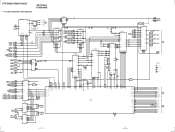
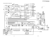
... L INPUT L SELECTOR IC303 27 23 26 25 24 20 22 21 17 CONTROL CE CLK DI 15 14 16 S LAT S CLK S DATA DIGITAL AUDIO I/F RECEIVER IC1101 DATA 16 CK OUT 13 3 D IN BCK 14 LRCK 15 12.288M 22 IC11404 IC1404 IC1404 36 DI 38 CLK 37 CE ERROR 34... SP RY U DATA U CLOCK U MREQ U SREQ U REST RESET RY POWER D STOP SOT0 SIN1 MD2 MD0 - 7 - - 8 - BLOCK DIAGRAM MAIN SECTION SECTION 4 DIAGRAMS TM301 ANTENNA FM 75Ω AM TUNER UNIT FM AM ANT LEVEL 6 FM DET 9 L OUT 10 RDS 2 4 IC1 16 13 14 X1 4.33MHz AEP ONLY R OUT 12 R CH DO TUNED STEREO T. STR-DB830/DB930/V929X 4-1.
... L INPUT L SELECTOR IC303 27 23 26 25 24 20 22 21 17 CONTROL CE CLK DI 15 14 16 S LAT S CLK S DATA DIGITAL AUDIO I/F RECEIVER IC1101 DATA 16 CK OUT 13 3 D IN BCK 14 LRCK 15 12.288M 22 IC11404 IC1404 IC1404 36 DI 38 CLK 37 CE ERROR 34... SP RY U DATA U CLOCK U MREQ U SREQ U REST RESET RY POWER D STOP SOT0 SIN1 MD2 MD0 - 7 - - 8 - BLOCK DIAGRAM MAIN SECTION SECTION 4 DIAGRAMS TM301 ANTENNA FM 75Ω AM TUNER UNIT FM AM ANT LEVEL 6 FM DET 9 L OUT 10 RDS 2 4 IC1 16 13 14 X1 4.33MHz AEP ONLY R OUT 12 R CH DO TUNED STEREO T. STR-DB830/DB930/V929X 4-1.
Service Manual
Page 7
... 7 6 9 6 ST-I /O BUFFER J701 PHONES L A TM501 R FRONT SPEAKER L B R • R-CH is omitted due to same as L-CH. • Signal Path :FM :CD C TM701 S(L) SURROUND SPEAKER S(R) L JJ101 SUB WOOFER R L REAR R L FRONT R JJ102 CENTER +5V PRE OUT +15V -15V +32V 1 +5V REG 3 Q801 +32V... RECEIVER RESET Q103 D1211 +6.2 REG Q1205 3 8 RESET 5 IC1206 6 IC1207 3 +5V REG 1 IC1501 3 +5V REG 1 IC1203 3 +3.3V REG 1 IC1204 3 +5V REG 1 IC1205 3 +6.2V REG 1 D806-809 F805 F2 F1 RELAY DRIVE Q901 RY901 D901-904 T902 JW927 JW928 J204 S-LINK - 9 - - 10 - STR-DB830/DB930...
... 7 6 9 6 ST-I /O BUFFER J701 PHONES L A TM501 R FRONT SPEAKER L B R • R-CH is omitted due to same as L-CH. • Signal Path :FM :CD C TM701 S(L) SURROUND SPEAKER S(R) L JJ101 SUB WOOFER R L REAR R L FRONT R JJ102 CENTER +5V PRE OUT +15V -15V +32V 1 +5V REG 3 Q801 +32V... RECEIVER RESET Q103 D1211 +6.2 REG Q1205 3 8 RESET 5 IC1206 6 IC1207 3 +5V REG 1 IC1501 3 +5V REG 1 IC1203 3 +3.3V REG 1 IC1204 3 +5V REG 1 IC1205 3 +6.2V REG 1 D806-809 F805 F2 F1 RELAY DRIVE Q901 RY901 D901-904 T902 JW927 JW928 J204 S-LINK - 9 - - 10 - STR-DB830/DB930...
Service Manual
Page 27
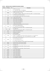
... data read Ground +3.3V HCIF ready signal Open drain HCIF chip select HCIF address input HCIF data input/output Ground +3.3V HCIF data input/output Reset input "L": active Test data output Ground External RAM data input/output Ground +3.3V External RAM data input/output Test data input "L" = normal "H" = test (Connected to...
... data read Ground +3.3V HCIF ready signal Open drain HCIF chip select HCIF address input HCIF data input/output Ground +3.3V HCIF data input/output Reset input "L": active Test data output Ground External RAM data input/output Ground +3.3V External RAM data input/output Test data input "L" = normal "H" = test (Connected to...
Service Manual
Page 29
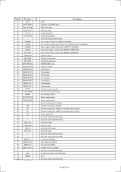
... To CXD9511Q clock 2 SI I To CXD9511Q data input 3 SO O To CXD9511Q data output 4 CS O To CXD9511Q chip select 5 IC O To CXD9511Q reset(Pull Down near CXD9511Q) 6 D.SIG I Not used (Connected to ground) 13 XHDWR O To CXD2712 data write 14 XHDRD O To CXD2712 data read 15 ...output. IC1201 MB90573PFV-G-190-BND SYSTEM CONTROL(DIGITAL BOARD) Pin No. Power supply +5 V 9 SIN0 I To AK4526A data output 32 PD O To AK4526A reset 33 VSS - Digital power supply +5 V 39 DVSS - Ground (Connected to ground) 46 EVSTB O To TC9299 strobe 47 EVDATA O To TC9299 data...
... To CXD9511Q clock 2 SI I To CXD9511Q data input 3 SO O To CXD9511Q data output 4 CS O To CXD9511Q chip select 5 IC O To CXD9511Q reset(Pull Down near CXD9511Q) 6 D.SIG I Not used (Connected to ground) 13 XHDWR O To CXD2712 data write 14 XHDRD O To CXD2712 data read 15 ...output. IC1201 MB90573PFV-G-190-BND SYSTEM CONTROL(DIGITAL BOARD) Pin No. Power supply +5 V 9 SIN0 I To AK4526A data output 32 PD O To AK4526A reset 33 VSS - Digital power supply +5 V 39 DVSS - Ground (Connected to ground) 46 EVSTB O To TC9299 strobe 47 EVDATA O To TC9299 data...
Service Manual
Page 30
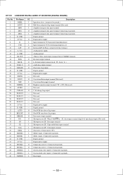
... U.CLOCK) Not used (Connected to ground) Power supply +5 V To tuner latch To tuner data To tuner clock PLL data in Auto stop input Stereo input Not used (Connected to ground) Not used (Connected to ground) Ground (Connected to ground) Not used (Connected to ground) TH Protector input...) Hardware standby (Connected to power supply +5 V) MD2 (To MCU MD2) MD1 (Connect to power supply) MD0 (To MCU MD0) Reset (Connected to MB90553 U.RESET) Ground (Connected to ground) External ceramic filter 16MHz is connected to this terminal External ceramic filter 16MHz is connected to this terminal Power supply...
... U.CLOCK) Not used (Connected to ground) Power supply +5 V To tuner latch To tuner data To tuner clock PLL data in Auto stop input Stereo input Not used (Connected to ground) Not used (Connected to ground) Ground (Connected to ground) Not used (Connected to ground) TH Protector input...) Hardware standby (Connected to power supply +5 V) MD2 (To MCU MD2) MD1 (Connect to power supply) MD0 (To MCU MD0) Reset (Connected to MB90553 U.RESET) Ground (Connected to ground) External ceramic filter 16MHz is connected to this terminal External ceramic filter 16MHz is connected to this terminal Power supply...
Service Manual
Page 32
... serial control register if P/S = "L" (Connected to ground) MCKO clock frequency select pin "L": MCLK, "H": MCLK/2. If the state of P/S, M/S, CAD0-1 changes, then the AK4526 must be reset by PD. Pin Name I/O 1 SDOS I I 2 MCLK 3 S/M I 4 BCLK I/O 5 LRCK I/O 6 SDT11 I 7 SDT12 I 8 SDT13 I 9 SDTO O 10 DAUX I 11 ... "H": X'tal oscillator selected "L": External clock source selected "NC": If pin is floating then test mode is powered-down & reset pin When "L", the AK4526 is enabled. (Connected to ground) Input clock select 1 pin (Connected to ground) Input clock ...
... serial control register if P/S = "L" (Connected to ground) MCKO clock frequency select pin "L": MCLK, "H": MCLK/2. If the state of P/S, M/S, CAD0-1 changes, then the AK4526 must be reset by PD. Pin Name I/O 1 SDOS I I 2 MCLK 3 S/M I 4 BCLK I/O 5 LRCK I/O 6 SDT11 I 7 SDT12 I 8 SDT13 I 9 SDTO O 10 DAUX I 11 ... "H": X'tal oscillator selected "L": External clock source selected "NC": If pin is floating then test mode is powered-down & reset pin When "L", the AK4526 is enabled. (Connected to ground) Input clock select 1 pin (Connected to ground) Input clock ...
Service Manual
Page 35
...LED CLR I 91 - - 92 - - 93 MBUS-V1 I 94 MBUS-DVD I 95 MBUS-TV I 96 MBUS-STATUS I 97 - - 98 LAT O 99 RESET O 100 - - Speaker B signal input. LED clear input. TV input from MBUS. Not used . (Connected to Ground) LED clock input. Description MD 2 Hardware .... Virsion input. Virsion output. Rotary encoder input. Virsion input. Function encoder down output Not used (Connected to Ground) Reset output (Connected to MB90573 RESET) Slave request and data input (Connected to MB90573 SLV DATA/REQ) Master request output (Connected to MB90573 DISPMR) Master data...
...LED CLR I 91 - - 92 - - 93 MBUS-V1 I 94 MBUS-DVD I 95 MBUS-TV I 96 MBUS-STATUS I 97 - - 98 LAT O 99 RESET O 100 - - Speaker B signal input. LED clear input. TV input from MBUS. Not used . (Connected to Ground) LED clock input. Description MD 2 Hardware .... Virsion input. Virsion output. Rotary encoder input. Virsion input. Function encoder down output Not used (Connected to Ground) Reset output (Connected to MB90573 RESET) Slave request and data input (Connected to MB90573 SLV DATA/REQ) Master request output (Connected to MB90573 DISPMR) Master data...
Service Manual
Page 36
... LRCK O L, R clock output terminal (L-ch: "H", R-ch: "L") 16 DATA O O Audio data output terminal 17 XSTATE O Xtal status frag output. 18 D. Data input terminal 37 CE I Microprocessor I /F RECEIVER (DIGITAL BOARD) Pin No. IC1101 LC89055W DIGITAL AUDIO I /F. Pin Name I/O Description 1 DISEL...
... LRCK O L, R clock output terminal (L-ch: "H", R-ch: "L") 16 DATA O O Audio data output terminal 17 XSTATE O Xtal status frag output. 18 D. Data input terminal 37 CE I Microprocessor I /F RECEIVER (DIGITAL BOARD) Pin No. IC1101 LC89055W DIGITAL AUDIO I /F. Pin Name I/O Description 1 DISEL...


