
Limited Warranty (ES Products)
Page 1
... THIS WARRANTY. For your authorized dealer, call : Sony Customer Information Services Center 1-800-222-7669 or visit the Sony Web Site: www.sony.com For an accessory or part not available from your convenience, Sony Electronics Inc. SONY SHALL NOT BE LIABLE FOR ANY INCIDENTAL OR CONSEQUENTIAL...To obtain warranty service, you , or for service assistance or resolution of a service problem, or for all labor charges. 2. PARTS: In addition, Sony will repair or replace the Product, at its original packaging or packaging affording an equal degree of protection, to obtain warranty service...
... THIS WARRANTY. For your authorized dealer, call : Sony Customer Information Services Center 1-800-222-7669 or visit the Sony Web Site: www.sony.com For an accessory or part not available from your convenience, Sony Electronics Inc. SONY SHALL NOT BE LIABLE FOR ANY INCIDENTAL OR CONSEQUENTIAL...To obtain warranty service, you , or for service assistance or resolution of a service problem, or for all labor charges. 2. PARTS: In addition, Sony will repair or replace the Product, at its original packaging or packaging affording an equal degree of protection, to obtain warranty service...
Operating Instructions (Large File - 21.32 MB)
Page 2
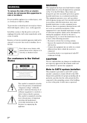
... to the presence of uninsulated "dangerous voltage" within the product's enclosure that to radio communications. CAUTION You are designed to Part 15 of trouble. Consult the dealer or an experienced radio/TV technician for proper grounding and, in the event of the ... this system so that any changes or modification not expressly approved in a residential installation. Increase the separation between the equipment and receiver. - Install this apparatus to persons. Batteries or batteries installed apparatus shall not be connected to the grounding system of the building...
... to the presence of uninsulated "dangerous voltage" within the product's enclosure that to radio communications. CAUTION You are designed to Part 15 of trouble. Consult the dealer or an experienced radio/TV technician for proper grounding and, in the event of the ... this system so that any changes or modification not expressly approved in a residential installation. Increase the separation between the equipment and receiver. - Install this apparatus to persons. Batteries or batteries installed apparatus shall not be connected to the grounding system of the building...
Operating Instructions (Large File - 21.32 MB)
Page 4
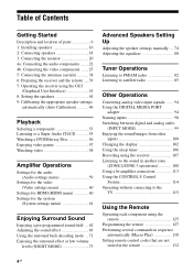
... and location of parts 6 1: Installing speakers 16 2: Connecting speakers 18 3: Connecting the monitor 20 4a: Connecting the audio components ........22 4b: Connecting the video components .......27 5: Connecting the antennas (aerials 38 6: Preparing the receiver and the remote ....39 7: Operating the receiver using the GUI ... MODE 99 Enjoying the sound/images from other inputs 100 Changing the display 102 Using the sleep timer 106 Recording using the receiver 107 Listening to the sound in another zone (ZONE 2/ZONE 3 operations 108 Using a bi-amplifier connection 113 Using the ...
... and location of parts 6 1: Installing speakers 16 2: Connecting speakers 18 3: Connecting the monitor 20 4a: Connecting the audio components ........22 4b: Connecting the video components .......27 5: Connecting the antennas (aerials 38 6: Preparing the receiver and the remote ....39 7: Operating the receiver using the GUI ... MODE 99 Enjoying the sound/images from other inputs 100 Changing the display 102 Using the sleep timer 106 Recording using the receiver 107 Listening to the sound in another zone (ZONE 2/ZONE 3 operations 108 Using a bi-amplifier connection 113 Using the ...
Operating Instructions (Large File - 21.32 MB)
Page 6
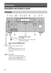
Press POWER to turn the receiver on using the remote. When you remove the cover, keep it to turn the receiver on . You cannot turn the receiver on the receiver, the receiver will be turned off (initial setting). Status of parts Front panel To remove the cover Press PUSH. When you press POWER on or set it out of reach from children. Getting Started Description and location of the POWER button Off The receiver is turned off . 6GB On/Standby Press ?/1 on the remote to the standby mode.
Press POWER to turn the receiver on using the remote. When you remove the cover, keep it to turn the receiver on . You cannot turn the receiver on the receiver, the receiver will be turned off (initial setting). Status of parts Front panel To remove the cover Press PUSH. When you press POWER on or set it out of reach from children. Getting Started Description and location of the POWER button Off The receiver is turned off . 6GB On/Standby Press ?/1 on the remote to the standby mode.
Operating Instructions (Large File - 21.32 MB)
Page 104
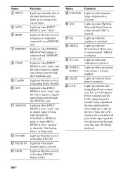
... contains an L.F.E. (Low Frequency Effects) channel and the L.F.E. Lights up when the sleep timer is selected. Lights up when multichannel input is activated. Lights up when the receiver is activated. Lights up while operation in all parts of the input indicators also lights up ...being reproduced, the bars underneath the letters light up when the receiver is actually being enabled. Name D INPUT E AUTO F HDMI G DMPORT H COAX I TrueHD J OPT K ANALOG L DTS-HD M MULTI IN N MSTR Function Lights up when the receiver recognizes a component connected via an HDMI IN jack. Lights up...
... contains an L.F.E. (Low Frequency Effects) channel and the L.F.E. Lights up when the sleep timer is selected. Lights up when multichannel input is activated. Lights up when the receiver is activated. Lights up while operation in all parts of the input indicators also lights up ...being reproduced, the bars underneath the letters light up when the receiver is actually being enabled. Name D INPUT E AUTO F HDMI G DMPORT H COAX I TrueHD J OPT K ANALOG L DTS-HD M MULTI IN N MSTR Function Lights up when the receiver recognizes a component connected via an HDMI IN jack. Lights up...
Operating Instructions (Large File - 21.32 MB)
Page 137
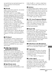
...spaces. S video uses a single cable and two channels, one for the Luminance signal Y and another for 6.1 channels playback. There are drawn. By adding a deep bass with stereo. "p" of a core and an extension, and the core part has DTS Digital Surround compatibility. x S video ...signal A format for digital video signals. continued 137GB Additional Information surround left and surround right channels. DTS-HD Master Audio has a the maximum transmission rate of ...
...spaces. S video uses a single cable and two channels, one for the Luminance signal Y and another for 6.1 channels playback. There are drawn. By adding a deep bass with stereo. "p" of a core and an extension, and the core part has DTS Digital Surround compatibility. x S video ...signal A format for digital video signals. continued 137GB Additional Information surround left and surround right channels. DTS-HD Master Audio has a the maximum transmission rate of ...
Operating Instructions (Large File - 21.32 MB)
Page 145
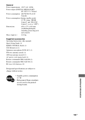
... standby mode) 0.7 W (when "HDMI Control" and "RS-232C Control" is set to "OFF") Dimensions 430 × 175 × 430 mm (width/height/depth) including projecting parts and controls Mass (Approx.) 16.0 kg Supplied accessories Operating Instructions (this manual) Quick Setup Guide (1) HDMI CONTROL Guide (1) GUI Menu List (1) Optimizer microphone ECM-AC1...
... standby mode) 0.7 W (when "HDMI Control" and "RS-232C Control" is set to "OFF") Dimensions 430 × 175 × 430 mm (width/height/depth) including projecting parts and controls Mass (Approx.) 16.0 kg Supplied accessories Operating Instructions (this manual) Quick Setup Guide (1) HDMI CONTROL Guide (1) GUI Menu List (1) Optimizer microphone ECM-AC1...


