

Operating Instructions
Page 3
Table of Contents Getting Started Installation Connecting the system Connection notes Audio connection diagram Connecting the speakers Connecting the AM antenna Connecting the FM antenna Connecting an antenna ground Connecting a turntable system Connecting a CD player Connecting a tape deck Connecting a DAT (Digital Audio ...
Table of Contents Getting Started Installation Connecting the system Connection notes Audio connection diagram Connecting the speakers Connecting the AM antenna Connecting the FM antenna Connecting an antenna ground Connecting a turntable system Connecting a CD player Connecting a tape deck Connecting a DAT (Digital Audio ...

Operating Instructions
Page 5
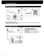
...ones for left-channel (L). White White R 04- A loose connection may cause hum and noise. AM antenna (supplied) Outdoor FM antenna FM antenna (supplied) (optional) Right speaker Left speake (See page 6) (See Page 7) iv' 0 (See page 6) Iv I O O OO 00 O OO O OO 00 00 (See page 9) LJ... CD player (See page 8) i771 o L DAT deck (See page 8) ' -I I Tapedeck 1(See page 8) mmImQ • (See Page 9) To the second speaker syst to the individual connection diagram. Connecting the System Connection Notes • The power cord should be connected last of all, first making sure that...
...ones for left-channel (L). White White R 04- A loose connection may cause hum and noise. AM antenna (supplied) Outdoor FM antenna FM antenna (supplied) (optional) Right speaker Left speake (See page 6) (See Page 7) iv' 0 (See page 6) Iv I O O OO 00 O OO O OO 00 00 (See page 9) LJ... CD player (See page 8) i771 o L DAT deck (See page 8) ' -I I Tapedeck 1(See page 8) mmImQ • (See Page 9) To the second speaker syst to the individual connection diagram. Connecting the System Connection Notes • The power cord should be connected last of all, first making sure that...
Operating Instructions
Page 6
... 0 4r1 75() Supplied loop- timmo) free antenna I 0,000 000000'01001 p @CD el0 00001 l= i ism -0 L Right speaker 1 Left speaker O O • • To the second speaker system. O O 2 15 mm O O I Speaker impedance and power capability This receiver is no need to work best with speakers having nominal impedance from 20 - 20,000 Hz. Connecting the System 0 Connecting the...
... 0 4r1 75() Supplied loop- timmo) free antenna I 0,000 000000'01001 p @CD el0 00001 l= i ism -0 L Right speaker 1 Left speaker O O • • To the second speaker system. O O 2 15 mm O O I Speaker impedance and power capability This receiver is no need to work best with speakers having nominal impedance from 20 - 20,000 Hz. Connecting the System 0 Connecting the...

Operating Instructions
Page 10
... diagram The circled numbers correspond to audio outputs armomi► 0 'MINN - a any misauswy 10 to video output -Eton -wpm. Monitor TV VCR 2 (for palyback only) Speaker system ® (See page 11) VCR 1(for recording and playback) (For details see below) iup iup lop • iup 0 0 0 0 O O C) @C,••• 0 00 ©0•...
... diagram The circled numbers correspond to audio outputs armomi► 0 'MINN - a any misauswy 10 to video output -Eton -wpm. Monitor TV VCR 2 (for palyback only) Speaker system ® (See page 11) VCR 1(for recording and playback) (For details see below) iup iup lop • iup 0 0 0 0 O O C) @C,••• 0 00 ©0•...

Operating Instructions
Page 12
BAND selectors (1) Display window fp 5 BAND GRAPHIC EQUALIZER 4 Remote control sensor SYSTEM POWER switch IP MO 0 TT ,"---. 1 HEADPHONES jack (stereo phone jack) SPEAKERS selectors (1) FM MODE button (P 12 Parts Identification 4- - Refer to the pages indicated in 0 for details.
BAND selectors (1) Display window fp 5 BAND GRAPHIC EQUALIZER 4 Remote control sensor SYSTEM POWER switch IP MO 0 TT ,"---. 1 HEADPHONES jack (stereo phone jack) SPEAKERS selectors (1) FM MODE button (P 12 Parts Identification 4- - Refer to the pages indicated in 0 for details.

Operating Instructions
Page 16
Balance Adjustment To change the relative strength of the right and left speaker output Adjust BALANCE to correct stereo imaging, when the speaker position is not symmetrical. • Sound Quality Adjustment To equalize a program source Slide the equalizer controls upward or downward to a stereo source. To enjOy surround ...
Balance Adjustment To change the relative strength of the right and left speaker output Adjust BALANCE to correct stereo imaging, when the speaker position is not symmetrical. • Sound Quality Adjustment To equalize a program source Slide the equalizer controls upward or downward to a stereo source. To enjOy surround ...

Operating Instructions
Page 17
...not enter the last "0". I Receiving FM/AM Broadcasts Tuning in a Station Directly-Direct Access Tuning SYSTEM POWER-ON 123 4 5 IZZl:=11=1 000 m Select SPEAKERS A or B. 1 Press TUNER. 2 Select FM or AM. 3 Press DIRECT. 4 Press the appropriate numeric buttons to 9 kHz, enter all the digits.... Example 1: FM 108.00 MHz Example 2: AM 1350 kHz I 00 O a) Select SPEAKERS A or B. 1 Press TUNER. 2 Press FM. 3 Press "+" or "-" TUNING. If the frequency figures flash in monaural, but the reception will be improved)....
...not enter the last "0". I Receiving FM/AM Broadcasts Tuning in a Station Directly-Direct Access Tuning SYSTEM POWER-ON 123 4 5 IZZl:=11=1 000 m Select SPEAKERS A or B. 1 Press TUNER. 2 Select FM or AM. 3 Press DIRECT. 4 Press the appropriate numeric buttons to 9 kHz, enter all the digits.... Example 1: FM 108.00 MHz Example 2: AM 1350 kHz I 00 O a) Select SPEAKERS A or B. 1 Press TUNER. 2 Press FM. 3 Press "+" or "-" TUNING. If the frequency figures flash in monaural, but the reception will be improved)....

Operating Instructions
Page 18
... preset to 10 kHz. "-": Starts Manual Tuning from 530 kHz. To change by 10 kHz. U DIRECT 8 0 • rIi I 2 314 =.0(= OOP PO= . k p_c rl ,', *4' 1 _ O CD Select SPEAKERS A or B. 1 Press TUNER. 2 Press AM. 3 Press "+" or "-" TUNING. To reset the AM tuning interval, repeat the above steps. 18 Caution When the interval is changed...
... preset to 10 kHz. "-": Starts Manual Tuning from 530 kHz. To change by 10 kHz. U DIRECT 8 0 • rIi I 2 314 =.0(= OOP PO= . k p_c rl ,', *4' 1 _ O CD Select SPEAKERS A or B. 1 Press TUNER. 2 Press AM. 3 Press "+" or "-" TUNING. To reset the AM tuning interval, repeat the above steps. 18 Caution When the interval is changed...

Operating Instructions
Page 19
SYSTEM POWER-ON 2 3 4 0 1 00 0 00 =1=1 Select SPEAKERS A or B. 'I Tune in any desired sequence. The previously preset station will be memorized in the desired station. (See pages 17 and 18.) 2 Press MEMORY MEMORY indicator appears for a few seconds. 3 Select the desired preset number (1 - 20) with numeric button, while the MEMORY indicator is displayed. 4 Press ENTER. Memorizing a Station-Memory Preset A total of the station to be replaced. Replacing a preset station Preset another station on the number of 20 FM/AM stations can be erased. 19
SYSTEM POWER-ON 2 3 4 0 1 00 0 00 =1=1 Select SPEAKERS A or B. 'I Tune in any desired sequence. The previously preset station will be memorized in the desired station. (See pages 17 and 18.) 2 Press MEMORY MEMORY indicator appears for a few seconds. 3 Select the desired preset number (1 - 20) with numeric button, while the MEMORY indicator is displayed. 4 Press ENTER. Memorizing a Station-Memory Preset A total of the station to be replaced. Replacing a preset station Preset another station on the number of 20 FM/AM stations can be erased. 19
Operating Instructions
Page 20
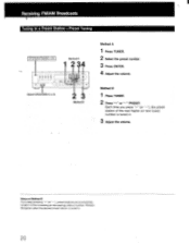
.... 2 Press "+" or "-" PRESET. Release the Qutton when the desired preset station is tuned in a Preset Station-Preset Tuning SYSTEM POWER-ON Method A 1 2 34 CI (1) Select SPEAKERS A or B. Method B Method A 1 Press TUNER. 2 Select the preset number. 3 Press ENTER. 4 Adjust the volume.
.... 2 Press "+" or "-" PRESET. Release the Qutton when the desired preset station is tuned in a Preset Station-Preset Tuning SYSTEM POWER-ON Method A 1 2 34 CI (1) Select SPEAKERS A or B. Method B Method A 1 Press TUNER. 2 Select the preset number. 3 Press ENTER. 4 Adjust the volume.

Operating Instructions
Page 21
...Simulcast ivIonttor TV TV tuner or VCR SYSTEM POWER-ON VIDEO 1 or VIDEO 2 IN 0 it • • • 0 00 0 MONITOR VIDEO OUT ./. .0 ' Select SPEAKERS 1 A or El. 1 Press VIDEO 1 or VIDEO 2. VIDEO 2: When the VHF antenna is ening o • rogram ources I er an Broadcasts I SYSTEM POWER ON 0 00... 000 0100 0100 001=Z1 00 I O Select SPEAKERS A or B. is connected to the TV tuner or VCR connected to the VIDEO 1 inputs. Turntable system CD player Tape deck DAT VCR 1 TV tuner or...
...Simulcast ivIonttor TV TV tuner or VCR SYSTEM POWER-ON VIDEO 1 or VIDEO 2 IN 0 it • • • 0 00 0 MONITOR VIDEO OUT ./. .0 ' Select SPEAKERS 1 A or El. 1 Press VIDEO 1 or VIDEO 2. VIDEO 2: When the VHF antenna is ening o • rogram ources I er an Broadcasts I SYSTEM POWER ON 0 00... 000 0100 0100 001=Z1 00 I O Select SPEAKERS A or B. is connected to the TV tuner or VCR connected to the VIDEO 1 inputs. Turntable system CD player Tape deck DAT VCR 1 TV tuner or...

Operating Instructions
Page 22
... DAT. 4 Start the playback of the VOLUME and equalizer controls do not have any effect on a Audio Tape Recording I SYSTEM POWER-ON Select SPEAKERS Aor B. 1 000 000 00,0 0=0 00 0 CC CD to TAPE or DAT REC OUT 2 DAT or tape deck Turntable system CD player VCR... 1 Select the desired program source. J , , ,==00=0==,..., 0 00 C 00 f- -T---1 0 o *1- Tape Dubbing SYSTEM POWER-ON 3 Select SPEAKERS A or B. - - Dubbing will start. For an FM/AM broadcast, tune in the desired station. 2 Set the DAT or tape deck in the recording mode. Recording...
... DAT. 4 Start the playback of the VOLUME and equalizer controls do not have any effect on a Audio Tape Recording I SYSTEM POWER-ON Select SPEAKERS Aor B. 1 000 000 00,0 0=0 00 0 CC CD to TAPE or DAT REC OUT 2 DAT or tape deck Turntable system CD player VCR... 1 Select the desired program source. J , , ,==00=0==,..., 0 00 C 00 f- -T---1 0 o *1- Tape Dubbing SYSTEM POWER-ON 3 Select SPEAKERS A or B. - - Dubbing will start. For an FM/AM broadcast, tune in the desired station. 2 Set the DAT or tape deck in the recording mode. Recording...
Operating Instructions
Page 23
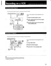
... To record the picture and the sound of a TV program, proceed as follows: SYSTEM POWER-ON 2,3 VCR 1 VIDEO 1 AUDIO OUT 1_,C= 00= 0=1,, MO C.= O 0 CI Select SPEAKERS A or B. Recording on a VCR To operate the VCR, refer to the VIDEO 2 inputs. • The volume and equalizer settings on the receiver do not have...
... To record the picture and the sound of a TV program, proceed as follows: SYSTEM POWER-ON 2,3 VCR 1 VIDEO 1 AUDIO OUT 1_,C= 00= 0=1,, MO C.= O 0 CI Select SPEAKERS A or B. Recording on a VCR To operate the VCR, refer to the VIDEO 2 inputs. • The volume and equalizer settings on the receiver do not have...
Operating Instructions
Page 24
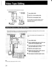
... Select the audio program source. 5 Release the pause mode of VCR 2 and set VCR 1 in the playback mode. SYSTEM POWER-ON Select SPEAKERS 1 A or B. Adding New Sound on a Video Tape During Editing During video tape editing, you can listen to an audio program source during ... VCR 1 in the recording mode. 3 Set VCR 2 in the recording mode. 6 Start playing the selected program source. SYSTEM POWER-O 2,3 VCR 2 Select SPEAKERS A or S. Note You cannot edit a video tape from another audio source, thus making your own personalized video tape. You can replace the sound previously recorded...
... Select the audio program source. 5 Release the pause mode of VCR 2 and set VCR 1 in the playback mode. SYSTEM POWER-ON Select SPEAKERS 1 A or B. Adding New Sound on a Video Tape During Editing During video tape editing, you can listen to an audio program source during ... VCR 1 in the recording mode. 3 Set VCR 2 in the recording mode. 6 Start playing the selected program source. SYSTEM POWER-O 2,3 VCR 2 Select SPEAKERS A or S. Note You cannot edit a video tape from another audio source, thus making your own personalized video tape. You can replace the sound previously recorded...
Operating Instructions
Page 25
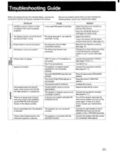
... interval according to disengage the stereo mode. One channel does not transmit audio, or the volume from the speakers The speakers are pressed. Adjust the BALANCE control. There is not connected correctly. Turn the TV on the power again. Press the appropriate... page 6.) Amplifier 25 The speaker or program source equipment is lack of the speakers, and the PROTECTOR indication flickers in the manual. A short-circuit problem activates the protective circuit. Press the FM MODE button to the AM frequency allocation system of your nearest Sony dealer. Adjust the antenna. ...
... interval according to disengage the stereo mode. One channel does not transmit audio, or the volume from the speakers The speakers are pressed. Adjust the BALANCE control. There is not connected correctly. Turn the TV on the power again. Press the appropriate... page 6.) Amplifier 25 The speaker or program source equipment is lack of the speakers, and the PROTECTOR indication flickers in the manual. A short-circuit problem activates the protective circuit. Press the FM MODE button to the AM frequency allocation system of your nearest Sony dealer. Adjust the antenna. ...

Operating Instructions
Page 27
... (14 lbs 13 oz) net Approx. 8.4 kg (18 lbs 9 oz) in shipping carton Accessories supplied FM ribbon antenna (1) AM loop antenna (1) Remote Commander RM-U80 Sony battery (NS) (2) (for the remote commander) SUM-3 Design and specifications subject to rated output. Loop antenna: 500µV (at 1,000 kHz) 54 dB (at 50... TAPE DAT 150mV 50 kilohms 100 dB 80 dB* (A. 150 mV) *'78 IHF Outputs REC OUT VIDEO (AUDIO) OUT Voltage 150 mV Impedance 10 kilohms SPEAKER A, B Accepts speakers of 8 - 16 ohms. HEADPHONES Accepts low and high impedance headphones.
... (14 lbs 13 oz) net Approx. 8.4 kg (18 lbs 9 oz) in shipping carton Accessories supplied FM ribbon antenna (1) AM loop antenna (1) Remote Commander RM-U80 Sony battery (NS) (2) (for the remote commander) SUM-3 Design and specifications subject to rated output. Loop antenna: 500µV (at 1,000 kHz) 54 dB (at 50... TAPE DAT 150mV 50 kilohms 100 dB 80 dB* (A. 150 mV) *'78 IHF Outputs REC OUT VIDEO (AUDIO) OUT Voltage 150 mV Impedance 10 kilohms SPEAKER A, B Accepts speakers of 8 - 16 ohms. HEADPHONES Accepts low and high impedance headphones.


