BRC-X400 / X401 / SRG-X400 / X402 / 201M2 / X120 / HD1M2 CGI Command List
Page 32
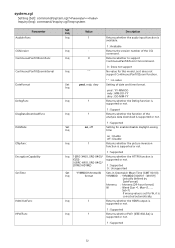
... time on : Enable off : Disable Inq 1 Returns whether the picture inversion function is supported or not. 1 : Supported Inq 1 (BRC-X400, SRG-X400/ Returns whether the HTTPS function is supported or not. 1 : Supported 32 Inq 1 Returns whether the HDMI output is supported or not. 1... : Supported Inq 1 Returns whether PoE+ (IEEE 802.3at) is X120) supported or not. 0 (BRC-X401, SRG-X402/ 201M2/HD1M2) 1 : Supported 0 : Unsupported Set YYMMDDhhmmssW Sets in Greenwich Mean Time (GMT 00:00)....
... time on : Enable off : Disable Inq 1 Returns whether the picture inversion function is supported or not. 1 : Supported Inq 1 (BRC-X400, SRG-X400/ Returns whether the HTTPS function is supported or not. 1 : Supported 32 Inq 1 Returns whether the HDMI output is supported or not. 1... : Supported Inq 1 Returns whether PoE+ (IEEE 802.3at) is X120) supported or not. 0 (BRC-X401, SRG-X402/ 201M2/HD1M2) 1 : Supported 0 : Unsupported Set YYMMDDhhmmssW Sets in Greenwich Mean Time (GMT 00:00)....

Operating Instructions
Page 2
...Screw Holes 16 Installing the camera on the ceiling ..... 16 Connecting the Camera 19 Connecting to an AC power supply ...... 19 Connecting the camera to a PoE+ (Power over Ethernet Plus) power supply device 20 Connecting a single camera to a switcher, recorder, or monitor 21 Connecting a single camera to a ...33 COLOR Menu 35 DETAIL Menu 37 KNEE Menu (BRC-X400/X401 38 GAMMA/VISIBILITY ENHANCER Menu (BRCX400/X401 38 GAMMA 38 VISIBILITY ENHANCER 39 VISIBILITY ENHANCER Menu (SRG-X400/ X402/201M2/X120/HD1M2 39 ZOOM/FOCUS Menu (BRC-X400/X401, SRGX400/X402/201M2 40 ZOOM 40 FOCUS 40 FOCUS...
...Screw Holes 16 Installing the camera on the ceiling ..... 16 Connecting the Camera 19 Connecting to an AC power supply ...... 19 Connecting the camera to a PoE+ (Power over Ethernet Plus) power supply device 20 Connecting a single camera to a switcher, recorder, or monitor 21 Connecting a single camera to a ...33 COLOR Menu 35 DETAIL Menu 37 KNEE Menu (BRC-X400/X401 38 GAMMA/VISIBILITY ENHANCER Menu (BRCX400/X401 38 GAMMA 38 VISIBILITY ENHANCER 39 VISIBILITY ENHANCER Menu (SRG-X400/ X402/201M2/X120/HD1M2 39 ZOOM/FOCUS Menu (BRC-X400/X401, SRGX400/X402/201M2 40 ZOOM 40 FOCUS 40 FOCUS...

Operating Instructions
Page 7
... over Ethernet Plus) The camera supports IEEE802.3at-compatible PoE+ (Power over IP protocol An IP connection can be loaded. Equipped with RS-422 interface The camera is equipped with RS-422 interface which is equipped with tally lamp (BRC-X400/ X401) The camera is the industry standard VISCA camera ... distinguishes cameras in use NDI|HX, you are required to purchase the license key (page 93). *1 20× optical zoom for the BRC-X400/X401 and SRG-X400/X402/201M2 12× optical zoom for power supply and control. By using these presets, an image texture gets close to the one shot...
... over Ethernet Plus) The camera supports IEEE802.3at-compatible PoE+ (Power over IP protocol An IP connection can be loaded. Equipped with RS-422 interface The camera is equipped with RS-422 interface which is equipped with tally lamp (BRC-X400/ X401) The camera is the industry standard VISCA camera ... distinguishes cameras in use NDI|HX, you are required to purchase the license key (page 93). *1 20× optical zoom for the BRC-X400/X401 and SRG-X400/X402/201M2 12× optical zoom for power supply and control. By using these presets, an image texture gets close to the one shot...

Operating Instructions
Page 8
... remote commander is pressed and the camera enters in the SYSTEM menu. Lens This is a 20× (BRC-X400/X401, SRG-X400/ X402/201M2) or 12x (SRG-X120/HD1M2) magnification-optical zoom lens. The lamp turns off while upgrading the firmware. The orange lamp flashes when there are ..., connect it is connected to the PoE+ power supply device with an remote controller (not supplied). Location and Function of Parts Camera Front ȩ *1 Ȫ ȫ Ȭ ȭ *1 This is not equipped on SRG-X400/X402/201M2/X120/HD1M2. Tally lamp (BRC-X400/X401) Lights up in the PAN...
... remote commander is pressed and the camera enters in the SYSTEM menu. Lens This is a 20× (BRC-X400/X401, SRG-X400/ X402/201M2) or 12x (SRG-X120/HD1M2) magnification-optical zoom lens. The lamp turns off while upgrading the firmware. The orange lamp flashes when there are ..., connect it is connected to the PoE+ power supply device with an remote controller (not supplied). Location and Function of Parts Camera Front ȩ *1 Ȫ ȫ Ȭ ȭ *1 This is not equipped on SRG-X400/X402/201M2/X120/HD1M2. Tally lamp (BRC-X400/X401) Lights up in the PAN...

Operating Instructions
Page 10
... label This label shows the name of device and its electric rating. Note Do not use the screw holes to the instruction manual of the PoE+ power supply device. For details, see "Installing the Camera" (page 16). Tripod socket hole Use this to attach the tripod, etc. Note Under... terminal Supplies the images as an HD signal. * Images are not output when 4K output is set. EXT SYNC IN (only BRC-X400/X401) Accepts an external sync signal. LAN (network) terminal (RJ-45) Network communication and PoE+ power supply are located at the bottom of the unit. 10
... label This label shows the name of device and its electric rating. Note Do not use the screw holes to the instruction manual of the PoE+ power supply device. For details, see "Installing the Camera" (page 16). Tripod socket hole Use this to attach the tripod, etc. Note Under... terminal Supplies the images as an HD signal. * Images are not output when 4K output is set. EXT SYNC IN (only BRC-X400/X401) Accepts an external sync signal. LAN (network) terminal (RJ-45) Network communication and PoE+ power supply are located at the bottom of the unit. 10

Operating Instructions
Page 20
... cord through the cord clamper and lock the cord clamper. 2 Fix the cord of an AC adapter with PoE+ power supply feature Notes • When you supply power from PoE+, both the POWER lamp (green) and NETWORK lamp (green) flash until the initial verification process is complete... cable. 20 AC adapter cord clamper Unlock the cord Cord clamper lock clamper lock. Connecting the camera to a PoE+ (Power over Ethernet Plus) power supply device A PoE+ (IEEE802.3at compliant) power supply device supplies power through a commercially available network cable. Note Do not use a network...
... cord through the cord clamper and lock the cord clamper. 2 Fix the cord of an AC adapter with PoE+ power supply feature Notes • When you supply power from PoE+, both the POWER lamp (green) and NETWORK lamp (green) flash until the initial verification process is complete... cable. 20 AC adapter cord clamper Unlock the cord Cord clamper lock clamper lock. Connecting the camera to a PoE+ (Power over Ethernet Plus) power supply device A PoE+ (IEEE802.3at compliant) power supply device supplies power through a commercially available network cable. Note Do not use a network...

Operating Instructions
Page 26
... Before operating, check that corresponds to the number set in step 2 lights up. 26 You can then operate the specified camera(s). Or, connect the powered PoE+ power supply device and the camera with a LAN cable. The power is turned on the camera again after putting it in the standby mode. Every...
... Before operating, check that corresponds to the number set in step 2 lights up. 26 You can then operate the specified camera(s). Or, connect the powered PoE+ power supply device and the camera with a LAN cable. The power is turned on the camera again after putting it in the standby mode. Every...

Operating Instructions
Page 95
... The AC adapter is not firmly connected to the LAN terminal. Check whether the connection method for RM-IP500/IP10 corresponds to the PoE+ power Firmly insert the connection cable all the way. Make sure that SELECT button number and the camera's matches the IR SELECT ...commander. The VISCA over IP) for the SYSTEM - Select [ON] for RMIP500/IP10 is required. If the problem still persists, consult the Sony Service Center. The connection method is incorrect. operated. HTTP/RTSP setting on the connected video monitor. The OSD menu is not connected properly. The...
... The AC adapter is not firmly connected to the LAN terminal. Check whether the connection method for RM-IP500/IP10 corresponds to the PoE+ power Firmly insert the connection cable all the way. Make sure that SELECT button number and the camera's matches the IR SELECT ...commander. The VISCA over IP) for the SYSTEM - Select [ON] for RMIP500/IP10 is required. If the problem still persists, consult the Sony Service Center. The connection method is incorrect. operated. HTTP/RTSP setting on the connected video monitor. The OSD menu is not connected properly. The...
Operating Instructions
Page 99
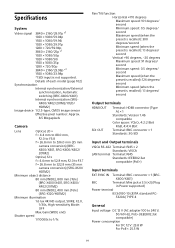
...V: 23.8 W For PoE+: 25.5 W 99 X400/X401) MIC Terminal: Mini jack ø 3.5 (×2) (Plug in Power supported) Power terminal IEC60130-10 (JEITA standard RC- 5320A) TYPE 4 General Input voltage DC 12 V (AC adapter 100 to 536.0 mm (35 mm camera conversion) (BRC- X400/X401, SRG-X400/X402/ 201M2) Optical....7 f = 26.8 mm to 322.8 mm (35 mm camera conversion) (SRG-X120/ HD1M2) Minimum object distance 80 mm (WIDE), 800 mm (Tele) (BRC-X400/X401, SRG-X400/ X402/201M2) 80 mm (WIDE), 400 mm (Tele) (SRG-X120/HD1M2) Minimum illumination 1.6 lux 4K/HD output, 50IRE, F2.0, 1/30s...
...V: 23.8 W For PoE+: 25.5 W 99 X400/X401) MIC Terminal: Mini jack ø 3.5 (×2) (Plug in Power supported) Power terminal IEC60130-10 (JEITA standard RC- 5320A) TYPE 4 General Input voltage DC 12 V (AC adapter 100 to 536.0 mm (35 mm camera conversion) (BRC- X400/X401, SRG-X400/X402/ 201M2) Optical....7 f = 26.8 mm to 322.8 mm (35 mm camera conversion) (SRG-X120/ HD1M2) Minimum object distance 80 mm (WIDE), 800 mm (Tele) (BRC-X400/X401, SRG-X400/ X402/201M2) 80 mm (WIDE), 400 mm (Tele) (SRG-X120/HD1M2) Minimum illumination 1.6 lux 4K/HD output, 50IRE, F2.0, 1/30s...
