Service Manual
Page 6
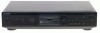
... fluorescent display tube. 3. The Rt value increases with each retry. is displayed in DRAM, number of the DRAM data amount enables data reading, accumulation, ejection, and writing to display the test mode (Fig. 1), and check the display. 9. RETRY CAUSE DISPLAY MODE • In this test mode, the ...causes for retry of the unit during recording can be erased into the unit. 2. To exit the test mode, press the 1/u button. Press the EDIT/NO button several times to display "Complete...
... fluorescent display tube. 3. The Rt value increases with each retry. is displayed in DRAM, number of the DRAM data amount enables data reading, accumulation, ejection, and writing to display the test mode (Fig. 1), and check the display. 9. RETRY CAUSE DISPLAY MODE • In this test mode, the ...causes for retry of the unit during recording can be erased into the unit. 2. To exit the test mode, press the 1/u button. Press the EDIT/NO button several times to display "Complete...
Service Manual
Page 8
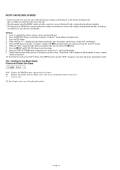
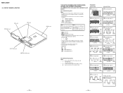
Location of Parts and Controls SECTION 2 GENERAL 1 23 4 5 6 7 89 1 1/u (Power) switch 2 Remote sensor 3 Display window 4 Disc compartment 5 AMS knob 6 0/) buttons 7 DISPLAY/CHAR button 8 INPUT switch !∞ !¢ !£ 9 REC LEVEL knob !£ r REC (recording) button !¢ p (stop) button !∞ P (pause) button !§ · (play) button !¶ YES button !• EDIT/NO button !ª § EJECT button - 8 -
Location of Parts and Controls SECTION 2 GENERAL 1 23 4 5 6 7 89 1 1/u (Power) switch 2 Remote sensor 3 Display window 4 Disc compartment 5 AMS knob 6 0/) buttons 7 DISPLAY/CHAR button 8 INPUT switch !∞ !¢ !£ 9 REC LEVEL knob !£ r REC (recording) button !¢ p (stop) button !∞ P (pause) button !§ · (play) button !¶ YES button !• EDIT/NO button !ª § EJECT button - 8 -
Service Manual
Page 13
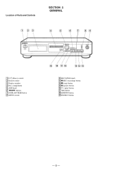
Be sure to press the §EJECT button after pressing the EDIT/NO button and the rotation of the tab. Continuous recording mode (CREC MODE) 2. When pressing the rREC button. 4-2. Function name Function AMS knob Changes parameters and modes YES button Proceeds onto ... using a disc that the disc is not detected in servicing. Electrical Adjustments". Even if the §EJECT button is pressed while the disc is rotating during continuous playback, continuous recording, etc., the disc will be performed regardless of the test mode operations being performed, be erased regardless ...
Be sure to press the §EJECT button after pressing the EDIT/NO button and the rotation of the tab. Continuous recording mode (CREC MODE) 2. When pressing the rREC button. 4-2. Function name Function AMS knob Changes parameters and modes YES button Proceeds onto ... using a disc that the disc is not detected in servicing. Electrical Adjustments". Even if the §EJECT button is pressed while the disc is rotating during continuous playback, continuous recording, etc., the disc will be performed regardless of the test mode operations being performed, be erased regardless ...
Service Manual
Page 14
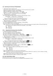
... Note : The numbers " " displayed show you the recording position addresses. 3. Entering the continuous recording mode 1 Set a recordable disc in the unit. REC goes off . 2 Press the §EJECT button to be used in the unit. (Whichever recordable discs or discs for long periods of time above 5 ...parts to remove the disc. The display will not be recorded 1 When the YES button is pressed during continuous playback to change to "CPLAY MODE". 2 Press the §EJECT button to be changed. Operating the Continuous Recording Mode 1. The display changes to "CREC MODE" and REC...
... Note : The numbers " " displayed show you the recording position addresses. 3. Entering the continuous recording mode 1 Set a recordable disc in the unit. REC goes off . 2 Press the §EJECT button to be used in the unit. (Whichever recordable discs or discs for long periods of time above 5 ...parts to remove the disc. The display will not be recorded 1 When the YES button is pressed during continuous playback to change to "CPLAY MODE". 2 Press the §EJECT button to be changed. Operating the Continuous Recording Mode 1. The display changes to "CREC MODE" and REC...
Service Manual
Page 16
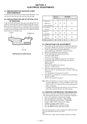
...¬ ¬ ¬ offset adjustment 2. PRECAUTIONS FOR ADJUSTMENTS 1) When replacing the following table. 2) Set the test mode when performing adjustments. Complete recording within 5 minutes. 5. Handle the flexible board with ¬ in the order shown in the optical pick-up . 5-4. J-2501-046-A) • Oscilloscope... Check Disc (MD) TDYS-1 (Parts No. 4-963-646-01) • Laser power meter LPM-8001 (Parts No. Press the §EJECT button and remove the disc. PRECAUTIONS FOR USE OF OPTICAL PICK- Laser power ¬ ¬ G ¬ adjustment 3. After completing the ...
...¬ ¬ ¬ offset adjustment 2. PRECAUTIONS FOR ADJUSTMENTS 1) When replacing the following table. 2) Set the test mode when performing adjustments. Complete recording within 5 minutes. 5. Handle the flexible board with ¬ in the order shown in the optical pick-up . 5-4. J-2501-046-A) • Oscilloscope... Check Disc (MD) TDYS-1 (Parts No. 4-963-646-01) • Laser power meter LPM-8001 (Parts No. Press the §EJECT button and remove the disc. PRECAUTIONS FOR USE OF OPTICAL PICK- Laser power ¬ ¬ G ¬ adjustment 3. After completing the ...
Service Manual
Page 18
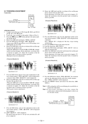
...of approx. 2%. Press the YES button, and save the adjustment results in the non-volatile memory. ("EFB = SAVE" will be erased during if a recorded disc is rotated, the of "EFB= " changes and the waveform changes.) In this adjustment, waveform varies at intervals of approx. 2%. Oscilloscope BD board ... value. Rotate the AMS knob and display "EFBAL ADJUST". 5. Adjust the waveform so that the waveform of the BD board. 2. Press the §EJECT button and remove the disc. 14. Next "EFBAL ADJUST" will be displayed. 18. Load a disc (any available on the market). (Refer to ...
...of approx. 2%. Press the YES button, and save the adjustment results in the non-volatile memory. ("EFB = SAVE" will be erased during if a recorded disc is rotated, the of "EFB= " changes and the waveform changes.) In this adjustment, waveform varies at intervals of approx. 2%. Oscilloscope BD board ... value. Rotate the AMS knob and display "EFBAL ADJUST". 5. Adjust the waveform so that the waveform of the BD board. 2. Press the §EJECT button and remove the disc. 14. Next "EFBAL ADJUST" will be displayed. 18. Load a disc (any available on the market). (Refer to ...
Service Manual
Page 19
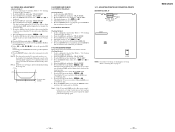
...- - ( )" is displayed. 5. Then press the YES button. 12. Press the EDIT/NO button, stop playback, press the §EJECT button, and remove the continuously recorded disc. 5-10. The display changes to "C1 = AD = ". 5. Rotate the AMS knob and display "CPLAY MODE". 3. Rotate the...= ". Check that the C1 error is 00. Press the EDIT/NO button, next press the §EJECT button, and remove the continuously recorded disc. in the above ) or b (step 7. Creating Continuously Recorded Disc".). 2. Rotate the AMS knob in the following figure. BIAS) a 5-9. MO Error Rate Check Checking...
...- - ( )" is displayed. 5. Then press the YES button. 12. Press the EDIT/NO button, stop playback, press the §EJECT button, and remove the continuously recorded disc. 5-10. The display changes to "C1 = AD = ". 5. Rotate the AMS knob and display "CPLAY MODE". 3. Rotate the...= ". Check that the C1 error is 00. Press the EDIT/NO button, next press the §EJECT button, and remove the continuously recorded disc. in the above ) or b (step 7. Creating Continuously Recorded Disc".). 2. Rotate the AMS knob in the following figure. BIAS) a 5-9. MO Error Rate Check Checking...
Service Manual
Page 22
... are taken with respect to normal production tolerances. • Waveforms are in µF unless otherwise noted. CIRCUIT BOARDS LOCATION SW board DISPLAY board BD board EJECT SW board CONTROL (SW) board - 25 -
... are taken with respect to normal production tolerances. • Waveforms are in µF unless otherwise noted. CIRCUIT BOARDS LOCATION SW board DISPLAY board BD board EJECT SW board CONTROL (SW) board - 25 -
Service Manual
Page 30
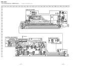
MDS-JE320 6-10. Printed Wiring Board - DISPLAY Section - • See page 25 for Circuit Boards Location. 1 2 3 4 5 6 7 8 9 A DISPLAY BOARD B C FLUORESCENT INDICATOR TUBE D 10 11 12 E E S764 1 3 21 1-661-891- (21) E F CONTROL (SW) BOARD REC LEVEL G H INPUT DIGITAL ANALOG C (PAGE 33) S762 DISPLAY/CHAR S774 S775 AMS (PUSH ENTER) 5 4 1 3 EJECT SW BOARD 1 S776 EJECT 3 CN705 21 1-661-893- (21) 1 3 I S771 S772 S780 S781 S752 S751 REC YES NO/EDIT 16 21 1-661-890- (21) - 41 - - 42 -
MDS-JE320 6-10. Printed Wiring Board - DISPLAY Section - • See page 25 for Circuit Boards Location. 1 2 3 4 5 6 7 8 9 A DISPLAY BOARD B C FLUORESCENT INDICATOR TUBE D 10 11 12 E E S764 1 3 21 1-661-891- (21) E F CONTROL (SW) BOARD REC LEVEL G H INPUT DIGITAL ANALOG C (PAGE 33) S762 DISPLAY/CHAR S774 S775 AMS (PUSH ENTER) 5 4 1 3 EJECT SW BOARD 1 S776 EJECT 3 CN705 21 1-661-893- (21) 1 3 I S771 S772 S780 S781 S752 S751 REC YES NO/EDIT 16 21 1-661-890- (21) - 41 - - 42 -

Service Manual
Page 48
...-247-A SW BOARD, COMPLETE (US,CND) A-4724-276-A SW BOARD, COMPLETE (AEP) 3-917-216-21 KNOB (TIMER) 4-983-653-41 BUTTON (MAIN) 1-661-893-11 EJECT SW BOARD Remark 63 4-977-593-11 RING (DIA. 50), ORNAMENTAL (AEP) - 64 - FRONT PANEL SECTION 56 not supplied 55 54 57 58 57 57...-355-1 PANEL ASSY, FRONT (AEP) 4-983-656-01 KNOB (REC) 4-983-657-01 KNOB (AMS) 4-983-651-01 WINDOW (DISPLAY) Remark 4-963-404-21 EMBLEM (5-A), SONY A-4724-246-A DISPLAY BOARD, COMPLETE (US,CND) A-4724-275-A DISPLAY BOARD, COMPLETE (AEP) 4-951-620-01 SCREW (2.6X8), +BVTP 1-777-276-11 WIRE (FLAT TYPE...
...-247-A SW BOARD, COMPLETE (US,CND) A-4724-276-A SW BOARD, COMPLETE (AEP) 3-917-216-21 KNOB (TIMER) 4-983-653-41 BUTTON (MAIN) 1-661-893-11 EJECT SW BOARD Remark 63 4-977-593-11 RING (DIA. 50), ORNAMENTAL (AEP) - 64 - FRONT PANEL SECTION 56 not supplied 55 54 57 58 57 57...-355-1 PANEL ASSY, FRONT (AEP) 4-983-656-01 KNOB (REC) 4-983-657-01 KNOB (AMS) 4-983-651-01 WINDOW (DISPLAY) Remark 4-963-404-21 EMBLEM (5-A), SONY A-4724-246-A DISPLAY BOARD, COMPLETE (US,CND) A-4724-275-A DISPLAY BOARD, COMPLETE (AEP) 4-951-620-01 SCREW (2.6X8), +BVTP 1-777-276-11 WIRE (FLAT TYPE...

Service Manual
Page 54
... BOARD Remarks < CONNECTOR > CN705 1-766-806-11 HOUSING, CONNECTOR 3P < SWITCH > S776 1-554-303-21 SWITCH, TACTILE (EJECT Ref. No. * Part No. No. Description 1-164-159-11 1-126-926-11 1-164-159-11 1-126-934-11 1-164-159-11 CERAMIC ELECT CERAMIC ELECT ...
... BOARD Remarks < CONNECTOR > CN705 1-766-806-11 HOUSING, CONNECTOR 3P < SWITCH > S776 1-554-303-21 SWITCH, TACTILE (EJECT Ref. No. * Part No. No. Description 1-164-159-11 1-126-926-11 1-164-159-11 1-126-934-11 1-164-159-11 CERAMIC ELECT CERAMIC ELECT ...
