
Operating Instructions
Page 2
... in the instructions within the product's enclosure that any changes or modification not expressly approved in this manual could void your authority to operate this manual Controls in accordance with news papers, table-cloths, curtains, etc. And don't place lighted candles ...FCC Rules. The following measures: - these instructions are designed to radio communications. As an ENERGY STAR® Partner, Sony Corporation has determined that are cautioned that may cause harmful interference to provide reasonable protection against harmful interference in a particular ...
... in the instructions within the product's enclosure that any changes or modification not expressly approved in this manual could void your authority to operate this manual Controls in accordance with news papers, table-cloths, curtains, etc. And don't place lighted candles ...FCC Rules. The following measures: - these instructions are designed to radio communications. As an ENERGY STAR® Partner, Sony Corporation has determined that are cautioned that may cause harmful interference to provide reasonable protection against harmful interference in a particular ...
Operating Instructions
Page 7
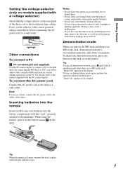
...with a voltage selector) Check that the voltage selector on the rear panel of the timer. For details, refer to the manual supplied with the + and - properly oriented to the MD deck. Demonstration mode When you use a timer, connect the AC power cord to a wall outlet. Tip When the remote... connections To connect a PC C PC connecting kit (not supplied) Use the PC connecting kit to connect a PC to the markings. By connecting the MD deck to a wall outlet. Inserting batteries into the remote Insert two R6 (size-AA) batteries into the remote casing, particularly when replacing the batteries. ...
...with a voltage selector) Check that the voltage selector on the rear panel of the timer. For details, refer to the manual supplied with the + and - properly oriented to the MD deck. Demonstration mode When you use a timer, connect the AC power cord to a wall outlet. Tip When the remote... connections To connect a PC C PC connecting kit (not supplied) Use the PC connecting kit to connect a PC to the markings. By connecting the MD deck to a wall outlet. Inserting batteries into the remote Insert two R6 (size-AA) batteries into the remote casing, particularly when replacing the batteries. ...
Operating Instructions
Page 10
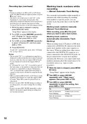
...displayed when the track is reduced. Notes • The recorded "LP:" is a confirmation stamp that does not support MD LP mode. Marking track numbers while recording - Marking track numbers manually (Manual Track Marking) While recording, press z at the point where you want to indicate that the track cannot be played ... recorded is noisy (e.g., tapes or radio programs). 1 While the deck is stopped, press MENU/ NO twice. When recording from a CD player or MD deck connected to a DIGITAL IN connector, the deck marks track numbers in the same sequence as part of the track name, so the number...
...displayed when the track is reduced. Notes • The recorded "LP:" is a confirmation stamp that does not support MD LP mode. Marking track numbers while recording - Marking track numbers manually (Manual Track Marking) While recording, press z at the point where you want to indicate that the track cannot be played ... recorded is noisy (e.g., tapes or radio programs). 1 While the deck is stopped, press MENU/ NO twice. When recording from a CD player or MD deck connected to a DIGITAL IN connector, the deck marks track numbers in the same sequence as part of the track name, so the number...

Service Manual
Page 1
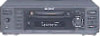
...output: 2 Vrms (at a distance of 200 mm from Dolby Laboratories. MINIDISC DECK 9-929-257-11 2001B0500-1 C 2001.2 Sony Corporation Audio Entertainment Group General Engineering Dept. Laser diode Revolutions (CLV) Error correction Sampling frequency Coding Modulation system Number of channels Frequency... TRansform Acoustic Coding)/ATRAC 3 EFM (Eight-to-Fourteen Modulation) 2 stereo channels 5 to change without notice. SERVICE MANUAL Ver 1.0 2001.02 MDS-S50 US Model Canadian Model AEP Model UK Model E Model Australian Model Photo: Gray model US and foreign patents licensed from...
...output: 2 Vrms (at a distance of 200 mm from Dolby Laboratories. MINIDISC DECK 9-929-257-11 2001B0500-1 C 2001.2 Sony Corporation Audio Entertainment Group General Engineering Dept. Laser diode Revolutions (CLV) Error correction Sampling frequency Coding Modulation system Number of channels Frequency... TRansform Acoustic Coding)/ATRAC 3 EFM (Eight-to-Fourteen Modulation) 2 stereo channels 5 to change without notice. SERVICE MANUAL Ver 1.0 2001.02 MDS-S50 US Model Canadian Model AEP Model UK Model E Model Australian Model Photo: Gray model US and foreign patents licensed from...
Service Manual
Page 5
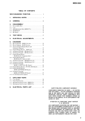
...PUBLIÉS PAR SONY. 5 DIAGRAMS 6-1. SERVO Section 33 6-2. MAIN Board (Conductor Side 41 6-9. EXPLODED VIEWS 7-1. SERVICING NOTES 7 2. ELECTRICAL ADJUSTMENTS 22 6. BD Board 37 6-5. Printed Wiring Board - Printed Wiring Board - ELECTRICAL PARTS LIST 62 SAFETY-RELATED COMPONENT WARNING!! MDS-S50 TABLE OF CONTENTS... IN THE PARTS LIST ARE CRITICAL TO SAFE OPERATION. REPLACE THESE COMPONENTS WITH SONY PARTS WHOSE PART NUMBERS APPEAR AS SHOWN IN THIS MANUAL OR IN SUPPLEMENTS PUBLISHED BY SONY. ATTENTION AU COMPOSANT AYANT RAPPORT À LA SÉCURITÉ! LES ...
...PUBLIÉS PAR SONY. 5 DIAGRAMS 6-1. SERVO Section 33 6-2. MAIN Board (Conductor Side 41 6-9. EXPLODED VIEWS 7-1. SERVICING NOTES 7 2. ELECTRICAL ADJUSTMENTS 22 6. BD Board 37 6-5. Printed Wiring Board - Printed Wiring Board - ELECTRICAL PARTS LIST 62 SAFETY-RELATED COMPONENT WARNING!! MDS-S50 TABLE OF CONTENTS... IN THE PARTS LIST ARE CRITICAL TO SAFE OPERATION. REPLACE THESE COMPONENTS WITH SONY PARTS WHOSE PART NUMBERS APPEAR AS SHOWN IN THIS MANUAL OR IN SUPPLEMENTS PUBLISHED BY SONY. ATTENTION AU COMPOSANT AYANT RAPPORT À LA SÉCURITÉ! LES ...

Service Manual
Page 12
Front Panel - SECTION 2 GENERAL This section is extracted from instruction manual. PHONE LEVEL w; (17) PHONES jack ql (17) PLAY MODE 4 (16) REC MODE qk (9) Remote sensor qh (7) YES 8 (10) (18) (20) BUTTON DESCRIPTIONS ?/1 (power)/STANDBY indicator 1 (8) ... (8) PC LINK AC power cord (Except for US, (Singapore, Canadian models) Brazilian models) to a wall outlet Amplifier, etc. 12 CD player, DBS tuner, etc.1) 1) Digital equipment with a DIGITAL OUT connector only MDS-S50 LOCATION OF CONTROLS - AMS qf (8) (10) (12) (13) (24) CLEAR qd (18) (24) Display qg (8) (17) INPUT qj (8) LEVEL/...
Front Panel - SECTION 2 GENERAL This section is extracted from instruction manual. PHONE LEVEL w; (17) PHONES jack ql (17) PLAY MODE 4 (16) REC MODE qk (9) Remote sensor qh (7) YES 8 (10) (18) (20) BUTTON DESCRIPTIONS ?/1 (power)/STANDBY indicator 1 (8) ... (8) PC LINK AC power cord (Except for US, (Singapore, Canadian models) Brazilian models) to a wall outlet Amplifier, etc. 12 CD player, DBS tuner, etc.1) 1) Digital equipment with a DIGITAL OUT connector only MDS-S50 LOCATION OF CONTROLS - AMS qf (8) (10) (12) (13) (24) CLEAR qd (18) (24) Display qg (8) (17) INPUT qj (8) LEVEL/...

Service Manual
Page 68
MDS-S50 POWER SW PT VOL SEL Ref. R775 R791 R792 R798 Part No. Replace only with marque 0 sont critiques pour la mark 0 are critical for safety. ..., LIGHT PLUG 1-776-263-11 CORD, CONNECTION 1-776-263-51 CORD, CONNECTION 4-230-403-11 MANUAL, INSTRUCTION (ENGLISH) 4-230-403-21 MANUAL, INSTRUCTION (FRENCH) (CND, AEP, SP) 4-230-403-31 MANUAL, INSTRUCTION (SPANISH) (AEP, SP, AR) 4-230-403-41 MANUAL, INSTRUCTION (GERMAN, DUTCH) (AEP) The components identified by Les composants identifiés par une...
MDS-S50 POWER SW PT VOL SEL Ref. R775 R791 R792 R798 Part No. Replace only with marque 0 sont critiques pour la mark 0 are critical for safety. ..., LIGHT PLUG 1-776-263-11 CORD, CONNECTION 1-776-263-51 CORD, CONNECTION 4-230-403-11 MANUAL, INSTRUCTION (ENGLISH) 4-230-403-21 MANUAL, INSTRUCTION (FRENCH) (CND, AEP, SP) 4-230-403-31 MANUAL, INSTRUCTION (SPANISH) (AEP, SP, AR) 4-230-403-41 MANUAL, INSTRUCTION (GERMAN, DUTCH) (AEP) The components identified by Les composants identifiés par une...

