Revision History
Page 3
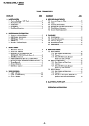
... 7-1-3. Leakage Test 3 1-4. Standby LED Error Display 6 6. DIAGRAMS 6-1. Printed Wiring Boards 25 6-5. Semiconductor 25 3. Rear Cabinet and Stand Assy 29 7-2-2. Rear Cabinet and Stand Assy 32 7-3-2. BG1, Power Unit (G2D), HG4A Boards, Speakers, Bezel Assy and LCD Panel 34 8. Aging 21 5-3. Accessing Service Menu 21 5-4. Factory Reset 22 5-5. Circuit Board Location 24 6-3. DISASSEMBLY 3-1. Stand Assy...
... 7-1-3. Leakage Test 3 1-4. Standby LED Error Display 6 6. DIAGRAMS 6-1. Printed Wiring Boards 25 6-5. Semiconductor 25 3. Rear Cabinet and Stand Assy 29 7-2-2. Rear Cabinet and Stand Assy 32 7-3-2. BG1, Power Unit (G2D), HG4A Boards, Speakers, Bezel Assy and LCD Panel 34 8. Aging 21 5-3. Accessing Service Menu 21 5-4. Factory Reset 22 5-5. Circuit Board Location 24 6-3. DISASSEMBLY 3-1. Stand Assy...

Revision History
Page 25
Complete board replacement is required if service is necessary. 6-2. CIRCUIT BOARD LOCATION KLV-26,32,32/H/S,37 S400A BG1 Board Block Switch Panel GP Board (KLV-26,32,32/H/S S400A) Power Unit (G2D Board) (KLV-37S400A) HG4 Board (KLV-26,32,32/H/S S400A) HG4A Board (KLV-37S400A) - 24 - BLOCK DIAGRAM SECTION 6 DIAGRAMS Due to complexity of the board, performing component level field repairs are not recommended. KLV-26,32,32/H/S,37 S400A RM-GA011 6-1.
Complete board replacement is required if service is necessary. 6-2. CIRCUIT BOARD LOCATION KLV-26,32,32/H/S,37 S400A BG1 Board Block Switch Panel GP Board (KLV-26,32,32/H/S S400A) Power Unit (G2D Board) (KLV-37S400A) HG4 Board (KLV-26,32,32/H/S S400A) HG4A Board (KLV-37S400A) - 24 - BLOCK DIAGRAM SECTION 6 DIAGRAMS Due to complexity of the board, performing component level field repairs are not recommended. KLV-26,32,32/H/S,37 S400A RM-GA011 6-1.
Revision History
Page 38
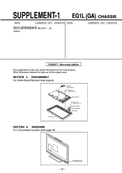
...EG1L (GA) CHASSIS MODEL COMMANDER DEST. SECTION 3. DISASSEMBLY 3-3. Circuit Board Location (refer page 24) HG4A Board - 37 - CHASSIS NO. CHASSIS NO. HG4A Board Removal (refer page 8) 2 Harness with connector 1 Two screws (+BVTP2 4 X 16) 3 LCD panel 5 Two screws (+BVTP2 3 X 12) 6 HG4A ...board 4 One connector Guide Light Bezel assy SECTION 6. MODEL KLV-32S400A/S RM-GA011 EA (Silver) COMMANDER DEST. Other information remains the same as in the original issue. DIAGRAMS 6-2.
...EG1L (GA) CHASSIS MODEL COMMANDER DEST. SECTION 3. DISASSEMBLY 3-3. Circuit Board Location (refer page 24) HG4A Board - 37 - CHASSIS NO. CHASSIS NO. HG4A Board Removal (refer page 8) 2 Harness with connector 1 Two screws (+BVTP2 4 X 16) 3 LCD panel 5 Two screws (+BVTP2 3 X 12) 6 HG4A ...board 4 One connector Guide Light Bezel assy SECTION 6. MODEL KLV-32S400A/S RM-GA011 EA (Silver) COMMANDER DEST. Other information remains the same as in the original issue. DIAGRAMS 6-2.