Revision History
Page 4
...IDENTIFIED IN THIS MANUAL. FOLLOW THESE PROCEDURES WHENEVER CRITICAL COMPONENTS ARE REPLACED OR IMPROPER OPERATION IS SUSPECTED. - 3 - When installing the LCD Panel on ... were installed during a previous repair. SAFETY-RELATED COMPONENT WARNING! KLV-26,32,32/H/S,37 S400A RM-GA011 SECTION 1 SAFETY NOTES 1-1. Caution Handling of the ...control knobs, shields, covers, ground straps and mounting hardware have an accurate low voltage scale. Nearly all the insulators. 4) Look for cracks and abrasion. Be ...SONY PARTS WHOSE PART NUMBERS APPEAR AS SHOWN IN THIS MANUAL OR IN SUPPLEMENTS PUBLISHED BY...
...IDENTIFIED IN THIS MANUAL. FOLLOW THESE PROCEDURES WHENEVER CRITICAL COMPONENTS ARE REPLACED OR IMPROPER OPERATION IS SUSPECTED. - 3 - When installing the LCD Panel on ... were installed during a previous repair. SAFETY-RELATED COMPONENT WARNING! KLV-26,32,32/H/S,37 S400A RM-GA011 SECTION 1 SAFETY NOTES 1-1. Caution Handling of the ...control knobs, shields, covers, ground straps and mounting hardware have an accurate low voltage scale. Nearly all the insulators. 4) Look for cracks and abrasion. Be ...SONY PARTS WHOSE PART NUMBERS APPEAR AS SHOWN IN THIS MANUAL OR IN SUPPLEMENTS PUBLISHED BY...
Revision History
Page 26
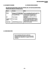
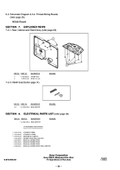
...the board, performing component level field repairs are not recommended. KLV-26,32,32/H/S,37 S400A RM-GA011 6-3. SCHEMATIC DIAGRAM 6-4. PRINTED WIRING BOARDS HG4 (KLV-26,32,32/H/S S400A), HG4A (KLV-37S400A), BG1, GP (KLV-26,32,32/H/S S400A), POWER UNIT (G2D) (KLV-37S400A) Boards. Complete board... replacement is required if service is necessary. SEMICONDUCTOR Due to Exploded View or Electrical Parts List section in this manual. 6-5. Complete board ...
...the board, performing component level field repairs are not recommended. KLV-26,32,32/H/S,37 S400A RM-GA011 6-3. SCHEMATIC DIAGRAM 6-4. PRINTED WIRING BOARDS HG4 (KLV-26,32,32/H/S S400A), HG4A (KLV-37S400A), BG1, GP (KLV-26,32,32/H/S S400A), POWER UNIT (G2D) (KLV-37S400A) Boards. Complete board... replacement is required if service is necessary. SEMICONDUCTOR Due to Exploded View or Electrical Parts List section in this manual. 6-5. Complete board ...
Revision History
Page 36
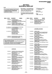
...,Philippines,South Africa,Thailand), 32/H(ME,South Africa,Thailand,Philippines) S400A) INDIVIDUAL CARTON (KLV-37S400A(South Africa,ME,Philippines,Thailand)) - 35 - PART NO. For part number information refer to complexity of this Service Manual. DESCRIPTION REMARK 1-966-103-21 1-966-102-21 HARNESS WITH ...Zealand)) BG1 MOUNT(SERVICE) (KLV-26S400A(New Zealand), 32S400A(New Zealand), 37S400A(New Zealand * A-1527-469-A HG4 MOUNT (KLV-26,32,32/H/S S400A) A-1548-456-A HG4A MOUNT (KLV-37S400A Due to the Exploded View or Electrical Parts List section of the board, performing component...
...,Philippines,South Africa,Thailand), 32/H(ME,South Africa,Thailand,Philippines) S400A) INDIVIDUAL CARTON (KLV-37S400A(South Africa,ME,Philippines,Thailand)) - 35 - PART NO. For part number information refer to complexity of this Service Manual. DESCRIPTION REMARK 1-966-103-21 1-966-102-21 HARNESS WITH ...Zealand)) BG1 MOUNT(SERVICE) (KLV-26S400A(New Zealand), 32S400A(New Zealand), 37S400A(New Zealand * A-1527-469-A HG4 MOUNT (KLV-26,32,32/H/S S400A) A-1548-456-A HG4A MOUNT (KLV-37S400A Due to the Exploded View or Electrical Parts List section of the board, performing component...
Revision History
Page 39
... 35) REF NO. Bhd. Printed Wiring Boards (refer page 25) HG4A Board SECTION 7. Schematic Diagram & 6-4. DESCRIPTION 103 * A-1548-456-A HG4A MOUNT REMARK SECTION 8. TV Operations of Pan Asia - 38 - 6-3. PART NO. PART NO. English 2008.4 PART NO. DESCRIPTION 2 * 3-106-086-01 COVER, ECS 4 3-700...-13 3-293-038-33 3-293-038-43 4-108-226-11 CUSHION, UPPER CUSHION, LOWER INDIVIDUAL CARTON INSTRUCTION (WALL MOUNT) MANUAL, INSTRUCTION MANUAL, INSTRUCTION MANUAL, INSTRUCTION MANUAL, INSTRUCTION (WALL MOUNT) 9-872-993-02 Sony Corporation Sony EMCS (Malaysia) Sdn.
... 35) REF NO. Bhd. Printed Wiring Boards (refer page 25) HG4A Board SECTION 7. Schematic Diagram & 6-4. DESCRIPTION 103 * A-1548-456-A HG4A MOUNT REMARK SECTION 8. TV Operations of Pan Asia - 38 - 6-3. PART NO. PART NO. English 2008.4 PART NO. DESCRIPTION 2 * 3-106-086-01 COVER, ECS 4 3-700...-13 3-293-038-33 3-293-038-43 4-108-226-11 CUSHION, UPPER CUSHION, LOWER INDIVIDUAL CARTON INSTRUCTION (WALL MOUNT) MANUAL, INSTRUCTION MANUAL, INSTRUCTION MANUAL, INSTRUCTION MANUAL, INSTRUCTION (WALL MOUNT) 9-872-993-02 Sony Corporation Sony EMCS (Malaysia) Sdn.
Revision History
Page 41
Introduction Thank you for future reference. Trademark information • HDMI, the HDMI logo and High-Definition Multimedia Interface are trademarks or registered trademarks of HDMI Licensing LLC. • "BRAVIA" and are of Sony Corporation. 2 GB The illustrations used in this Sony product. Before operating the TV, please read this manual thoroughly and retain it for choosing this manual are trademarks of the KLV-32S400A unless otherwise stated.
Introduction Thank you for future reference. Trademark information • HDMI, the HDMI logo and High-Definition Multimedia Interface are trademarks or registered trademarks of HDMI Licensing LLC. • "BRAVIA" and are of Sony Corporation. 2 GB The illustrations used in this Sony product. Before operating the TV, please read this manual thoroughly and retain it for choosing this manual are trademarks of the KLV-32S400A unless otherwise stated.
Revision History
Page 57
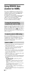
...play. • If you can operate the connected Sony equipment that is compatible with the function, using F/f/G/g and . - After displaying the menu, you turn on a connected audio system while the TV is compatible with control for HDMI function enables the TV to the sound from "Menu", "Options", and "... to display "Device Control", then select options from the TV on the screen. Be sure to the instruction manual of the connected HDMI CEC equipment which is compatible with an HDMI cable. When connecting an audio system, in page 15) to listen to communicate with the connected...
...play. • If you can operate the connected Sony equipment that is compatible with the function, using F/f/G/g and . - After displaying the menu, you turn on a connected audio system while the TV is compatible with control for HDMI function enables the TV to the sound from "Menu", "Options", and "... to display "Device Control", then select options from the TV on the screen. Be sure to the instruction manual of the connected HDMI CEC equipment which is compatible with an HDMI cable. When connecting an audio system, in page 15) to listen to communicate with the connected...
Revision History
Page 61
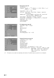
... Direct": "On" t "Off" "Favourite Set-up" "Auto Tuning" "Programme Sorting" "Programme Labels" "Programme Block" "Intelligent Picture": "On with Indicator"t "On"t "Off" "Manual Programme Preset": "Programme", "TV System", "VHF Low"/ "VHF High"/ "UHF", "Label", "AFT", "Audio Filter", "Skip", "Colour System", "Signal Booster", "Signal Level" ~ • The options you can adjust vary depending on the situation.
... Direct": "On" t "Off" "Favourite Set-up" "Auto Tuning" "Programme Sorting" "Programme Labels" "Programme Block" "Intelligent Picture": "On with Indicator"t "On"t "Off" "Manual Programme Preset": "Programme", "TV System", "VHF Low"/ "VHF High"/ "UHF", "Label", "AFT", "Audio Filter", "Skip", "Colour System", "Signal Booster", "Signal Level" ~ • The options you can adjust vary depending on the situation.
Revision History
Page 67
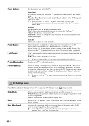
...then press . Resets all settings to reduce the power consumption of the TV. Sleep Timer Sets a period of the picture when the TV receives an input signal from standby mode. Clock Set Allows you want to adjust the clock manually. Displays your PC, see page 13. To keep them, select "...Cancel" in the room. Press F/f to the factory settings. Wide Mode Reset Auto Adjustment Selects a screen mode for displaying input from your TV's product information. Timer Settings Power Saving ...
...then press . Resets all settings to reduce the power consumption of the TV. Sleep Timer Sets a period of the picture when the TV receives an input signal from standby mode. Clock Set Allows you want to adjust the clock manually. Displays your PC, see page 13. To keep them, select "...Cancel" in the room. Press F/f to the factory settings. Wide Mode Reset Auto Adjustment Selects a screen mode for displaying input from your TV's product information. Timer Settings Power Saving ...
Revision History
Page 70
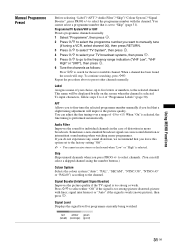
..."On" is selected, the fine tuning is too strong or weak. signal interference) or "Auto" if the signal is selected. Programme/TV System/VHF or UHF Presets programme channels manually. 1 Select "Programme", then press . 2 Press F/f to select the programme number you to "Skip" (page 31). Sometimes a ...can still select a skipped channel using the number buttons.) Colour System Selects the colour system ("Auto", "PAL", "SECAM", "NTSC3.58", "NTSC4.43" or "PAL60") according to the factory setting "Off". ~ • You cannot receive stereo or dual sound when "Low" or "High" is set to the...
..."On" is selected, the fine tuning is too strong or weak. signal interference) or "Auto" if the signal is selected. Programme/TV System/VHF or UHF Presets programme channels manually. 1 Select "Programme", then press . 2 Press F/f to select the programme number you to "Skip" (page 31). Sometimes a ...can still select a skipped channel using the number buttons.) Colour System Selects the colour system ("Auto", "PAL", "SECAM", "NTSC3.58", "NTSC4.43" or "PAL60") according to the factory setting "Off". ~ • You cannot receive stereo or dual sound when "Low" or "High" is set to the...
Revision History
Page 72
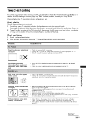
If the problem persists, contact your dealer or Sony service centre of how the indicator flashes (number of flashes)....8226; Check the connection between the optional equipment and the TV. • Check if the antenna is not flashing 1 Check the items listed below or use . • Select "Manual Programme Preset" in the "Channel Set-up in red... self-diagnosis function is activated. 1 Count how many 1 (standby) indicator flashes between the optional equipment and the TV. • Check the antenna/cable connection. • Keep the antenna cable away from electrical noise sources such as...
If the problem persists, contact your dealer or Sony service centre of how the indicator flashes (number of flashes)....8226; Check the connection between the optional equipment and the TV. • Check if the antenna is not flashing 1 Check the items listed below or use . • Select "Manual Programme Preset" in the "Channel Set-up in red... self-diagnosis function is activated. 1 Count how many 1 (standby) indicator flashes between the optional equipment and the TV. • Check the antenna/cable connection. • Keep the antenna cable away from electrical noise sources such as...
Revision History
Page 73
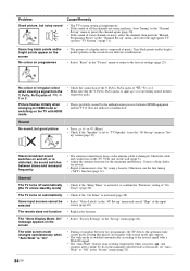
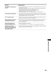
...Remedy • The TV system setting is damaged. up " menu in the "Channel Set-up" menu, and select the appropriate TV system ("TV System") (page 31). Check the cable and connection on the TV, VCR, and ... does not indicate a malfunction. Try using a booster. To fix in the manually selected wide screen mode, set to "TV Speaker" from the Y, PB/CB, PR/CR jacks of / 1 or ...transmission is probably caused by the authentication process between HDMI equipment and the TV. Contact a Sony dealer for the minimum interference. Problem Good picture, but good picture • Press ...
...Remedy • The TV system setting is damaged. up " menu in the "Channel Set-up" menu, and select the appropriate TV system ("TV System") (page 31). Check the cable and connection on the TV, VCR, and ... does not indicate a malfunction. Try using a booster. To fix in the manually selected wide screen mode, set to "TV Speaker" from the Y, PB/CB, PR/CR jacks of / 1 or ...transmission is probably caused by the authentication process between HDMI equipment and the TV. Contact a Sony dealer for the minimum interference. Problem Good picture, but good picture • Press ...
Revision History
Page 74
...; The antenna connection is loose or the antenna cable is damaged. Contact a Sony dealer for advice. • Signal transmission is dry, for example in winter. Additional Information 35 ... when audio is output directly from the connected equipment to receive Text. For details, see the instruction manual supplied with your TV. This does not indicate a malfunction. • Check the antenna/cable connection. • Set the...using an external booster. • Adjust the sound delay settings from the amplifier system Cause/Remedy • Your area may improve the picture (page 31). • Some shooting...
...; The antenna connection is loose or the antenna cable is damaged. Contact a Sony dealer for advice. • Signal transmission is dry, for example in winter. Additional Information 35 ... when audio is output directly from the connected equipment to receive Text. For details, see the instruction manual supplied with your TV. This does not indicate a malfunction. • Check the antenna/cable connection. • Set the...using an external booster. • Adjust the sound delay settings from the amplifier system Cause/Remedy • Your area may improve the picture (page 31). • Some shooting...
Revision History
Page 77
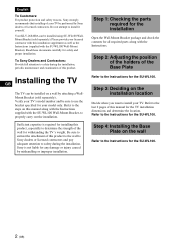
... this product, especially to the last 2 pages of this manual along with the Instructions. Refer to determine the strength of the wall for safety and proper installation. English To Customers: For product protection and safety reasons, Sony strongly recommends that installing of your TV. Step 1: Checking the parts required for the installation Open...
... this product, especially to the last 2 pages of this manual along with the Instructions. Refer to determine the strength of the wall for safety and proper installation. English To Customers: For product protection and safety reasons, Sony strongly recommends that installing of your TV. Step 1: Checking the parts required for the installation Open...
