
Operating Instructions
Page 1
2-668-009-13(1) LCD HDTV Monitor Operating Instructions KLV-32U100M KLV-40U100M © 2006 Sony Corporation
2-668-009-13(1) LCD HDTV Monitor Operating Instructions KLV-32U100M KLV-40U100M © 2006 Sony Corporation

Operating Instructions
Page 2
... contact the Direct Response Center at: 1-800-222-SONY (7669) or visit http://www.sony.com/TVsupport Customers in the spaces provided below. Record these numbers in Canada contact the Customer Relations Center at the rear of your Sony dealer regarding this product. Owner's Record The model ...and serial numbers are located at : 1-877-899-SONY (7669) or visit http://www.sony.com/TVsupport 2 Refer to them whenever you call upon your Sony® unit, please call one of the following instructions, you have additional questions related to ...
... contact the Direct Response Center at: 1-800-222-SONY (7669) or visit http://www.sony.com/TVsupport Customers in the spaces provided below. Record these numbers in Canada contact the Customer Relations Center at the rear of your Sony dealer regarding this product. Owner's Record The model ...and serial numbers are located at : 1-877-899-SONY (7669) or visit http://www.sony.com/TVsupport 2 Refer to them whenever you call upon your Sony® unit, please call one of the following instructions, you have additional questions related to ...

Operating Instructions
Page 3
... page 4 and "Important Safeguards" on 120 V AC. Use with part 15 of the following two conditions: (1) This device may be placed on the apparatus. KLV-32U100M KLV-40U100M SONY WALL-MOUNT BRACKET MODEL NO. These limits are unable to insert the plug fully into the outlet, contact your authority to operate this equipment does...
... page 4 and "Important Safeguards" on 120 V AC. Use with part 15 of the following two conditions: (1) This device may be placed on the apparatus. KLV-32U100M KLV-40U100M SONY WALL-MOUNT BRACKET MODEL NO. These limits are unable to insert the plug fully into the outlet, contact your authority to operate this equipment does...

Operating Instructions
Page 4
... For installation of BBE Sound, Inc. Trademark Information WOW, SRS and the symbol are trademarks of SONY WALL-MOUNT BRACKET, be regulated if sold with those optional products. "BBE" and BBE symbol are trademarks of the obsolete outlet. 10) Protect ...use caution when moving the cart/apparatus combination to qualified service personnel. As an ENERGY STAR® Partner, Sony Corporation has determined that produce heat. 9) Do not defeat the safety purpose of Sony Corporation. If the provided plug does not fit into the apparatus, the apparatus has been exposed to Apple...
... For installation of BBE Sound, Inc. Trademark Information WOW, SRS and the symbol are trademarks of SONY WALL-MOUNT BRACKET, be regulated if sold with those optional products. "BBE" and BBE symbol are trademarks of the obsolete outlet. 10) Protect ...use caution when moving the cart/apparatus combination to qualified service personnel. As an ENERGY STAR® Partner, Sony Corporation has determined that produce heat. 9) Do not defeat the safety purpose of Sony Corporation. If the provided plug does not fit into the apparatus, the apparatus has been exposed to Apple...

Operating Instructions
Page 5
... not being turned on the AC power cord. If the AC power cord is a safety feature. Disposal of used batteries according to your dealer or Sony service center to grasp the plug when disconnecting the AC power cord. The apparatus shall not be removed with a cloth slightly dampened with liquids, such...
... not being turned on the AC power cord. If the AC power cord is a safety feature. Disposal of used batteries according to your dealer or Sony service center to grasp the plug when disconnecting the AC power cord. The apparatus shall not be removed with a cloth slightly dampened with liquids, such...

Operating Instructions
Page 6
... easily at the unit. Follow your eyes or mouth, rinse the contacted area thoroughly with general household waste. s Do not expose the LCD screen surface to the unit. These phenomena improve as its light source. Moisture and flammable objects s Do not use of the unit....a smear may occur in moderate brightness. Fluorescent lamp This unit uses a special fluorescent lamp as the temperature rises. It may result. LCD screen s Although the LCD screen is toxic), with care. Volume adjustment s Adjust the volume so as to 7 times that of broken glass and liquid crystal ...
... easily at the unit. Follow your eyes or mouth, rinse the contacted area thoroughly with general household waste. s Do not expose the LCD screen surface to the unit. These phenomena improve as its light source. Moisture and flammable objects s Do not use of the unit....a smear may occur in moderate brightness. Fluorescent lamp This unit uses a special fluorescent lamp as the temperature rises. It may result. LCD screen s Although the LCD screen is toxic), with care. Volume adjustment s Adjust the volume so as to 7 times that of broken glass and liquid crystal ...

Operating Instructions
Page 7
s Do not install the unit in a location where the unit protrudes, such as follows: Air circulation is provided. Oils Do not install this unit outdoors. s Do not install the unit turned over or upside down and cause injury. Otherwise, adequate air-circulation may fall down . If the unit is exposed to the unit. If the unit is exposed to direct sunlight, the unit may heat up and cause damage to seawater, it may be blocked or covered. Optional accessories Observe the following : s Do not install the unit turned backward or sideways. If the unit is provided, the unit may...
s Do not install the unit in a location where the unit protrudes, such as follows: Air circulation is provided. Oils Do not install this unit outdoors. s Do not install the unit turned over or upside down and cause injury. Otherwise, adequate air-circulation may fall down . If the unit is exposed to the unit. If the unit is exposed to direct sunlight, the unit may heat up and cause damage to seawater, it may be blocked or covered. Optional accessories Observe the following : s Do not install the unit turned backward or sideways. If the unit is provided, the unit may...

Operating Instructions
Page 8
The unit may fall from the wall outlet. Service Damage requiring service Unplug the unit from the wall outlet and refer servicing to qualified service personnel under the following the operating instructions. Unauthorized substitutions may fall and cause injury or damage. s If the unit does not operate normally when following conditions: s When the power cord or plug is subject to dispose of other hazards. Installing on a level surface If you install the unit on a non-level surface, the unit may result in fire, electric shock or other hazards. Do not move the unit with ...
The unit may fall from the wall outlet. Service Damage requiring service Unplug the unit from the wall outlet and refer servicing to qualified service personnel under the following the operating instructions. Unauthorized substitutions may fall and cause injury or damage. s If the unit does not operate normally when following conditions: s When the power cord or plug is subject to dispose of other hazards. Installing on a level surface If you install the unit on a non-level surface, the unit may result in fire, electric shock or other hazards. Do not move the unit with ...

Operating Instructions
Page 9
... Unit Making Video and Audio Connections 17 Satellite Receiver 18 VCR and Cable 19 HD Equipment 20 DVD Player 22 HDMI-Equipped Device 24 DVI-HDTV-Equipped Device 25 Personal Computer 26 Camcorder or Video Game Equipment 27 Using the Unit Button Descriptions 28 Special Buttons on the Remote Control........... 29... Settings 36 Selecting Screen Options 36 Selecting PC Screen Options 38 Using the Setup Settings 40 Selecting Setup Options 40 Other Information Troubleshooting 42 Contacting Sony 43 Specifications 44 Index 45 9
... Unit Making Video and Audio Connections 17 Satellite Receiver 18 VCR and Cable 19 HD Equipment 20 DVD Player 22 HDMI-Equipped Device 24 DVI-HDTV-Equipped Device 25 Personal Computer 26 Camcorder or Video Game Equipment 27 Using the Unit Button Descriptions 28 Special Buttons on the Remote Control........... 29... Settings 36 Selecting Screen Options 36 Selecting PC Screen Options 38 Using the Setup Settings 40 Selecting Setup Options 40 Other Information Troubleshooting 42 Contacting Sony 43 Specifications 44 Index 45 9

Operating Instructions
Page 10
...-digital audio/video interface between this Sony HDTV Ready LCD unit. HDMI supports enhanced, or highdefinition video, plus two-channel digital audio. s PC Input: PC Input allows you to connect your new unit, the packaging box contains a remote control, size AA batteries. This manual is for models KLV-32U100M and KLV-40U100M. Along with your unit...
...-digital audio/video interface between this Sony HDTV Ready LCD unit. HDMI supports enhanced, or highdefinition video, plus two-channel digital audio. s PC Input: PC Input allows you to connect your new unit, the packaging box contains a remote control, size AA batteries. This manual is for models KLV-32U100M and KLV-40U100M. Along with your unit...

Operating Instructions
Page 11
Introducing the Unit Installing the Unit Preventing the Unit from toppling over and causing injury. You will need screws that are 3 to 4 mm (1/8 to the stand, and screw the belt with the wall-mount bracket on a Wall See the Instruction Guide supplied with a securing screw (supplied) using a coin, etc. 3 Adjust the length by pulling the support belt towards you can use for this unit and your dealer about the type of screw you while holding the unit stand. Consult your stand. When Mounting on how to prevent the unit from Toppling Over Attaching the Support Belt ...
Introducing the Unit Installing the Unit Preventing the Unit from toppling over and causing injury. You will need screws that are 3 to 4 mm (1/8 to the stand, and screw the belt with the wall-mount bracket on a Wall See the Instruction Guide supplied with a securing screw (supplied) using a coin, etc. 3 Adjust the length by pulling the support belt towards you can use for this unit and your dealer about the type of screw you while holding the unit stand. Consult your stand. When Mounting on how to prevent the unit from Toppling Over Attaching the Support Belt ...

Operating Instructions
Page 12
Introducing the Unit Bundling the Connecting Cables You can bundle the connecting cables as illustrated below. 12
Introducing the Unit Bundling the Connecting Cables You can bundle the connecting cables as illustrated below. 12

Operating Instructions
Page 13
Press to select the menu options in the MENU screen. 3 Bb In the MENU screen, these buttons serve as up/down buttons. 5 POWER Press to turn on and off the unit. 6 Headphones jack Connects to display MENU. For details, see page 41. Press again to exit MENU. 2 INPUT/ Press repeatedly to cycle through the external equipment connected to adjust the volume. Use it as left/right buttons. 4 vV - If your headphones. The VOLUME + button has a tactile dot. In the MENU screen, these buttons serve as a reference when operating the unit. (Continued) 13 VOLUME + Press ...
Press to select the menu options in the MENU screen. 3 Bb In the MENU screen, these buttons serve as up/down buttons. 5 POWER Press to turn on and off the unit. 6 Headphones jack Connects to display MENU. For details, see page 41. Press again to exit MENU. 2 INPUT/ Press repeatedly to cycle through the external equipment connected to adjust the volume. Use it as left/right buttons. 4 vV - If your headphones. The VOLUME + button has a tactile dot. In the MENU screen, these buttons serve as a reference when operating the unit. (Continued) 13 VOLUME + Press ...
Operating Instructions
Page 14
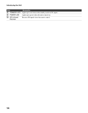
Lights up in red when in green when the unit is turned on. Receives IR signals from the remote control. 14 Introducing the Unit Item 8 STANDBY LED 9 POWER LED 0 (IR) Infrared Receiver Description Lights up in the standby mode for PC inputs.
Lights up in red when in green when the unit is turned on. Receives IR signals from the remote control. 14 Introducing the Unit Item 8 STANDBY LED 9 POWER LED 0 (IR) Infrared Receiver Description Lights up in the standby mode for PC inputs.

Operating Instructions
Page 15
S VIDEO provides better picture quality than the S VIDEO (1, 3) or the composite video (2, 4) connections. 15 Connect to your VCR or other video component. Component video provides better picture quality than the composite video (4). S VIDEO provides better picture quality than the composite video (2). Introducing the Unit Rear Panel VIDEO IN 1 Introducing the Unit S VIDEO VIDEO L (MONO) AUDIO R VIDEO IN 2 S VIDEO VIDEO L (MONO) AUDIO R HD/DVD IN 3 (1080i/720p/480p/480i) Y PB PR L AUDIO R Jack 1 VIDEO IN 1 S VIDEO 2 VIDEO IN 1 VIDEO/ L (MONO) AUDIO-R 3 VIDEO IN 2 S VIDEO 4 ...
S VIDEO provides better picture quality than the S VIDEO (1, 3) or the composite video (2, 4) connections. 15 Connect to your VCR or other video component. Component video provides better picture quality than the composite video (4). S VIDEO provides better picture quality than the composite video (2). Introducing the Unit Rear Panel VIDEO IN 1 Introducing the Unit S VIDEO VIDEO L (MONO) AUDIO R VIDEO IN 2 S VIDEO VIDEO L (MONO) AUDIO R HD/DVD IN 3 (1080i/720p/480p/480i) Y PB PR L AUDIO R Jack 1 VIDEO IN 1 S VIDEO 2 VIDEO IN 1 VIDEO/ L (MONO) AUDIO-R 3 VIDEO IN 2 S VIDEO 4 ...

Operating Instructions
Page 16
See page 25 for DVI connection. See "PC Input Signal Compatibility Chart" on page 39 for the signal to be connected to a personal computer's video and audio output jacks. The AUDIO IN (R/L) of HDMI IN is for details. Can be displayed. 16 HDMI supports enhanced, or high-definition video, plus two-channel digital audio. Introducing the Unit Bottom Panel AC IN IN 4 AUDIO IN RL PC IN 5 AUDIO RGB Jack 1 AC IN 2 HDMI IN 4 HDMI/ R-AUDIO IN-L 3 PC IN 5 RGB/AUDIO Description Connects the supplied AC power cord. Connect to other Analog RGB devices such as a set-top box, DVD ...
See page 25 for DVI connection. See "PC Input Signal Compatibility Chart" on page 39 for the signal to be connected to a personal computer's video and audio output jacks. The AUDIO IN (R/L) of HDMI IN is for details. Can be displayed. 16 HDMI supports enhanced, or high-definition video, plus two-channel digital audio. Introducing the Unit Bottom Panel AC IN IN 4 AUDIO IN RL PC IN 5 AUDIO RGB Jack 1 AC IN 2 HDMI IN 4 HDMI/ R-AUDIO IN-L 3 PC IN 5 RGB/AUDIO Description Connects the supplied AC power cord. Connect to other Analog RGB devices such as a set-top box, DVD ...

Operating Instructions
Page 17
When connecting your devices that are connected, the S VIDEO input is automatically selected. To view the VIDEO input, disconnect the S VIDEO cable. 17 Connector type Separate audio connection required HDMI (High-Definition Multimedia Interface) No PB PR Component video (1080i/720p/480p/480i) S VIDEO Yes L-AUDIO-R Composite video When both S VIDEO and VIDEO inputs are available on page 29). Connecting the Unit Connecting the Unit To display clear crisp pictures, first you must connect your unit correctly and also need to choose the correct display format (see "Changing ...
When connecting your devices that are connected, the S VIDEO input is automatically selected. To view the VIDEO input, disconnect the S VIDEO cable. 17 Connector type Separate audio connection required HDMI (High-Definition Multimedia Interface) No PB PR Component video (1080i/720p/480p/480i) S VIDEO Yes L-AUDIO-R Composite video When both S VIDEO and VIDEO inputs are available on page 29). Connecting the Unit Connecting the Unit To display clear crisp pictures, first you must connect your unit correctly and also need to choose the correct display format (see "Changing ...

Operating Instructions
Page 18
To connect a satellite receiver 1 Connect the satellite antenna cable to the satellite receiver's satellite input jack. 2 Use an A/V and S VIDEO cables to connect the satellite receiver's AUDIO and S VIDEO output jacks to the unit Do This ... See the instructions for setting up Label Video Inputs on the remote control. Press V1 or V2 on page 40. 18 Watch the satellite receiver Label video inputs to easily identify equipment connected to the unit's AUDIO and S VIDEO input jacks (VIDEO 1 or 2). Satellite Receiver Satellite antenna cable S VIDEO cable S VIDEO VIDEO (yellow) A/V...
To connect a satellite receiver 1 Connect the satellite antenna cable to the satellite receiver's satellite input jack. 2 Use an A/V and S VIDEO cables to connect the satellite receiver's AUDIO and S VIDEO output jacks to the unit Do This ... See the instructions for setting up Label Video Inputs on the remote control. Press V1 or V2 on page 40. 18 Watch the satellite receiver Label video inputs to easily identify equipment connected to the unit's AUDIO and S VIDEO input jacks (VIDEO 1 or 2). Satellite Receiver Satellite antenna cable S VIDEO cable S VIDEO VIDEO (yellow) A/V...
Operating Instructions
Page 19
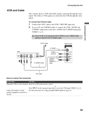
VCR CATV cable S VIDEO cable S VIDEO VIDEO (yellow) AUDIO-L (white) AUDIO-R (red) Rear of the S VIDEO cable. or Press INPUT on Using This Connection To Do This ... Watch the VCR or cable channels Press V1 or V2 on page 40. identify equipment connected to the unit's AUDIO and S VIDEO input jacks (VIDEO 1 or 2). Do This ... Label video inputs to easily See the instructions for setting up Label Video Inputs on the remote control. The Cable or VCR signals are selected by the VCR through the video inputs. To connect the VCR and cable 1 Connect the CATV cable to the ...
VCR CATV cable S VIDEO cable S VIDEO VIDEO (yellow) AUDIO-L (white) AUDIO-R (red) Rear of the S VIDEO cable. or Press INPUT on Using This Connection To Do This ... Watch the VCR or cable channels Press V1 or V2 on page 40. identify equipment connected to the unit's AUDIO and S VIDEO input jacks (VIDEO 1 or 2). Do This ... Label video inputs to easily See the instructions for setting up Label Video Inputs on the remote control. The Cable or VCR signals are selected by the VCR through the video inputs. To connect the VCR and cable 1 Connect the CATV cable to the ...

Operating Instructions
Page 20
Disconnect all format types of the HD equipment you can connect to provide sound. The YPBPR jacks do not provide audio, so audio cables must be connected to receive the broadcasting signals are digital cable box, digital satellite receiver and digital TV receiver. 20 Component video cable HD Equipment with Component Video Audio cable Y PB PR AUDIO-L (white) AUDIO-R (red) Rear of unit HD/DVD IN 3 (1080i/720p/480p/480i) Y PB PR L AUDIO R Some of picture in a resolution 1,366 dots × 768 lines. 2 Using an audio cable, connect your equipment's AUDIO output jacks to the unit's ...
Disconnect all format types of the HD equipment you can connect to provide sound. The YPBPR jacks do not provide audio, so audio cables must be connected to receive the broadcasting signals are digital cable box, digital satellite receiver and digital TV receiver. 20 Component video cable HD Equipment with Component Video Audio cable Y PB PR AUDIO-L (white) AUDIO-R (red) Rear of unit HD/DVD IN 3 (1080i/720p/480p/480i) Y PB PR L AUDIO R Some of picture in a resolution 1,366 dots × 768 lines. 2 Using an audio cable, connect your equipment's AUDIO output jacks to the unit's ...