Operating Instructions
Page 4
... Sony Corporation. It is transported directly from SRS Labs, Inc. SU-PF1 (for PDM-4200/5000) NIPPON SHEET GLASS CO., LTD Trademark Information TruSurround and the symbol are located at temperatures below . s Do not install the TV in a hot or humid place, or in the spaces provided below 5°C (41°F). KE-42XBR900 (PDM-4200) KE-50XBR900 (PDM-5000...
... Sony Corporation. It is transported directly from SRS Labs, Inc. SU-PF1 (for PDM-4200/5000) NIPPON SHEET GLASS CO., LTD Trademark Information TruSurround and the symbol are located at temperatures below . s Do not install the TV in a hot or humid place, or in the spaces provided below 5°C (41°F). KE-42XBR900 (PDM-4200) KE-50XBR900 (PDM-5000...
Operating Instructions
Page 15
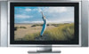
... used with the following models: s KE-42XBR900 s KE-50XBR900 The package contains the following: s Flat panel display unit (PDM-5000 or PDM-4200) s Media receiver unit (MBT...-XBR900) s Remote control (RM-927Y) and two size AAA (LR03) batteries s Two AC power cords s AC plug holder s Display interface cable s Antenna cable s Cleaning cloth s Operating Instructions These items are all you need to connect your new TV include: s WEGA...the Sony Flat Panel Color TV. This engine features unique Sony technology, including: • The first step in...
... used with the following models: s KE-42XBR900 s KE-50XBR900 The package contains the following: s Flat panel display unit (PDM-5000 or PDM-4200) s Media receiver unit (MBT...-XBR900) s Remote control (RM-927Y) and two size AAA (LR03) batteries s Two AC power cords s AC plug holder s Display interface cable s Antenna cable s Cleaning cloth s Operating Instructions These items are all you need to connect your new TV include: s WEGA...the Sony Flat Panel Color TV. This engine features unique Sony technology, including: • The first step in...
Operating Instructions
Page 103
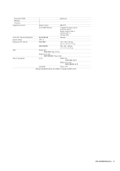
...) Impedance (output): 2 kilohms ×1 1 phono jack 2 1 KE-42XBR900 42 inches KE-50XBR900 50 inches 15W × 2 PDM-4200 1352 × 720 × 102 mm (53 1/4 × 28 3/8 × 4 1/8 in) PDM-5000 1573 × 856 × 108 mm (62 1/8 × ...Television System Channel Coverage Power Requirements Inputs/Outputs DVI-HDTV Video (IN) S Video (IN) Audio (IN) Component Video Input CONTROL S (OUT) Variable/Fixed Audio (OUT) Monitor/Fixed Audio (OUT) Sub woofer (OUT) RF Inputs Converter Screen Size (measured diagonally) Speaker Output Dimensions (W × H × D) Mass Plasma...
...) Impedance (output): 2 kilohms ×1 1 phono jack 2 1 KE-42XBR900 42 inches KE-50XBR900 50 inches 15W × 2 PDM-4200 1352 × 720 × 102 mm (53 1/4 × 28 3/8 × 4 1/8 in) PDM-5000 1573 × 856 × 108 mm (62 1/8 × ...Television System Channel Coverage Power Requirements Inputs/Outputs DVI-HDTV Video (IN) S Video (IN) Audio (IN) Component Video Input CONTROL S (OUT) Variable/Fixed Audio (OUT) Monitor/Fixed Audio (OUT) Sub woofer (OUT) RF Inputs Converter Screen Size (measured diagonally) Speaker Output Dimensions (W × H × D) Mass Plasma...

Operating Instructions
Page 104
Other Info 102 Power Consumption Supplied Accessories In Use Display unit PDM-4200: 460 W PDM-5000: 540 W Media receiver unit MBT-XBR900: 36 W In Standby Under 1.5 W Remote Control (1) RM-927Y AAA (LR03) Batteries (2) AC power code (2) AC plug holder (1) Display interface cable (1) Antenna cable (1) Cleaning cloth (1) Design and specifications are subject to change without notice.
Other Info 102 Power Consumption Supplied Accessories In Use Display unit PDM-4200: 460 W PDM-5000: 540 W Media receiver unit MBT-XBR900: 36 W In Standby Under 1.5 W Remote Control (1) RM-927Y AAA (LR03) Batteries (2) AC power code (2) AC plug holder (1) Display interface cable (1) Antenna cable (1) Cleaning cloth (1) Design and specifications are subject to change without notice.

Operating Instructions
Page 105
Optional Accessories s A/V Cable (VMC-810/820/830 HG) s Audio Cable (RKC-515HG) s Component Video Cable (VMC-10/30 HG) s Control S Cable (RK-G69HG) s 10M display interface cable (VMC-P10) s Memory Stick media: 8 MB (MSA-8A); 16 MB (MSA-16A); 32 MB (MSA-32A); 64 MB (MSA-64A); 128 MB (MSA-128A) s Table top stand: SU-P42T1 (for PDM-4200) SU-P50T1 (for PDM-5000) s Wall mount unit: SU-PW1 (for PDM-4200/5000) s Floating stand: SU-PF1 (for PDM-4200/5000) 103 Other Info
Optional Accessories s A/V Cable (VMC-810/820/830 HG) s Audio Cable (RKC-515HG) s Component Video Cable (VMC-10/30 HG) s Control S Cable (RK-G69HG) s 10M display interface cable (VMC-P10) s Memory Stick media: 8 MB (MSA-8A); 16 MB (MSA-16A); 32 MB (MSA-32A); 64 MB (MSA-64A); 128 MB (MSA-128A) s Table top stand: SU-P42T1 (for PDM-4200) SU-P50T1 (for PDM-5000) s Wall mount unit: SU-PW1 (for PDM-4200/5000) s Floating stand: SU-PF1 (for PDM-4200/5000) 103 Other Info
Marketing Specifications
Page 2
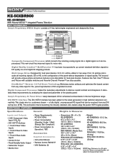
...KE-50XBR900: KE-50XBR900: 121.2 lbs. 617/8" x 333/4" x 41/4" (157.3 x 85.6 x 10.8mm) KE-42XBR900: 533/8"x 281/2"x 41/8" (135.3 x 72 x 10.3mm) MBT-XBR900 (Media Box): 167/8" x 41/8" x 141/8" (43 x 10.5 x 36mm) PDM-5000 (KE-50XBR900): (55kgs) KE-42XBR900: 99.2 lbs. (45kgs) MBT-XBR900: 15.9 lbs. (7.5kg) PDM-5000: 116.8 lbs. (53.0kg) PDM...(in high definition television connectivity. Product Information KE-50XBR900 KE- 42XBR900 XBR Plasma WEGA™ Integrated Plasma Television KEY TECHNOLOGY Sony's Proprietary WEGA Engine consists of the plasma panel. Sony's Proprietary IC Panel ...
...KE-50XBR900: KE-50XBR900: 121.2 lbs. 617/8" x 333/4" x 41/4" (157.3 x 85.6 x 10.8mm) KE-42XBR900: 533/8"x 281/2"x 41/8" (135.3 x 72 x 10.3mm) MBT-XBR900 (Media Box): 167/8" x 41/8" x 141/8" (43 x 10.5 x 36mm) PDM-5000 (KE-50XBR900): (55kgs) KE-42XBR900: 99.2 lbs. (45kgs) MBT-XBR900: 15.9 lbs. (7.5kg) PDM-5000: 116.8 lbs. (53.0kg) PDM...(in high definition television connectivity. Product Information KE-50XBR900 KE- 42XBR900 XBR Plasma WEGA™ Integrated Plasma Television KEY TECHNOLOGY Sony's Proprietary WEGA Engine consists of the plasma panel. Sony's Proprietary IC Panel ...
Service Manual
Page 3
... Consumption 1 phono jack 2 1 Remote Control RM-927Y AAA (LR03) Batteries 2 supplied for remote control AC power code (2) Display interface cable (1) Antenna cable (1) Cleaning cloth KE-50XBR900 50 inches 15W ×2 PDM-5000 1573 × 856 × 108 mm (62 1/8 × 33 3/4 × 4 3/8 in) MBT-XBR900 430 × 105 × 360 mm (17 × 4 1/4 × 14...
... Consumption 1 phono jack 2 1 Remote Control RM-927Y AAA (LR03) Batteries 2 supplied for remote control AC power code (2) Display interface cable (1) Antenna cable (1) Cleaning cloth KE-50XBR900 50 inches 15W ×2 PDM-5000 1573 × 856 × 108 mm (62 1/8 × 33 3/4 × 4 3/8 in) MBT-XBR900 430 × 105 × 360 mm (17 × 4 1/4 × 14...

Service Manual
Page 8
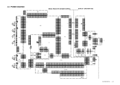
... Removal 1-20 2. Circuit Boards Location 4-3-1.Display Unit(PDM-5000 4-16 KE-50XBR900(UC) 7 Display Unit (PDM-5000) 1-1-1.Rear Cover Removal 1-1 1-1-2.K and F Boards Removal 1-2 1-1-3.P Board Removal 1-3 1-1-4.G and F2 Boards Removal 1-4 1-1-5.R1 Board Removal 1-5 1-1-6.R2 Board Removal 1-6 1-2. White Balance Adjustment (PDM-5000 2-2 3. VS, VD Voltage Adjustment (PDM-5000 2-1 2-2. DIAGRAMS 4-1. Display Unit (PDM-5000 3-1 3-2. Block Diagrams 4-1-1.Display Unit(PDM-5000 4-1 4-1-2.Media Receiver Unit (MBT-XBR900 4-6 4-2. TABLE OF...
... Removal 1-20 2. Circuit Boards Location 4-3-1.Display Unit(PDM-5000 4-16 KE-50XBR900(UC) 7 Display Unit (PDM-5000) 1-1-1.Rear Cover Removal 1-1 1-1-2.K and F Boards Removal 1-2 1-1-3.P Board Removal 1-3 1-1-4.G and F2 Boards Removal 1-4 1-1-5.R1 Board Removal 1-5 1-1-6.R2 Board Removal 1-6 1-2. White Balance Adjustment (PDM-5000 2-2 3. VS, VD Voltage Adjustment (PDM-5000 2-1 2-2. DIAGRAMS 4-1. Display Unit (PDM-5000 3-1 3-2. Block Diagrams 4-1-1.Display Unit(PDM-5000 4-1 4-1-2.Media Receiver Unit (MBT-XBR900 4-6 4-2. TABLE OF...

Service Manual
Page 9
... Unit (MBT-XBR900 4-17 4-4. EXPLODED VIEWS 5-1 5-1. ELECTRICAL PARTS LIST 6-1 KE-50XBR900(UC) 8 Semiconductors 4-71 5. Display Unit (PDM-5000 5-2 5-2. Packing Materials for Media Receiver Unit (MBT-XBR900 5-8 6. Packing Materials for Display Unit (PDM-5000) ........ 5-7 5-5. Media Receiver Unit-2 (MBT-XBR900 5-6 5-4. Schematic Diagrams and Printed WiringBoards....... 4-18 4-4-1.Display Unit(PDM-5000 4-19 (1)Schematic Diagrams of F Board 4-19 (2)Schematic Diagram of F2...
... Unit (MBT-XBR900 4-17 4-4. EXPLODED VIEWS 5-1 5-1. ELECTRICAL PARTS LIST 6-1 KE-50XBR900(UC) 8 Semiconductors 4-71 5. Display Unit (PDM-5000 5-2 5-2. Packing Materials for Media Receiver Unit (MBT-XBR900 5-8 6. Packing Materials for Display Unit (PDM-5000) ........ 5-7 5-5. Media Receiver Unit-2 (MBT-XBR900 5-6 5-4. Schematic Diagrams and Printed WiringBoards....... 4-18 4-4-1.Display Unit(PDM-5000 4-19 (1)Schematic Diagrams of F Board 4-19 (2)Schematic Diagram of F2...

Service Manual
Page 10
REAR COVER REMOVAL 1 SECTION 1 DISASSEMBLY 2 Three screws (+PSW 3X8) 1 Eight screws (+PSW 5X16) 3 Ten screws (+BVTP 4X16) 4 Rear cover assy 3 Ten screws (+BVTP 4X16) KE-50XBR900(UC) 1-1 PANEL UNIT (PDM-5000) 1-1-1. 1-1.
REAR COVER REMOVAL 1 SECTION 1 DISASSEMBLY 2 Three screws (+PSW 3X8) 1 Eight screws (+PSW 5X16) 3 Ten screws (+BVTP 4X16) 4 Rear cover assy 3 Ten screws (+BVTP 4X16) KE-50XBR900(UC) 1-1 PANEL UNIT (PDM-5000) 1-1-1. 1-1.

Service Manual
Page 30
... to right Fig.) 5. Disconnect an AC cord of SONY LOGO LED. 3. Assure that "POWER ON/STANDBY" LEDs is flashing amber. Rear cover assy BAR CODE SEAL SERIAL No. 301201440 Vd=65V Vs=193.4V CODE AA-01 Panel unit KE-50XBR900(UC) 2-1 VS, VD Voltage Adjustment (PDM-5000) 1 SECTION 2 ADJUSTMENTS • Preparation for each model...
... to right Fig.) 5. Disconnect an AC cord of SONY LOGO LED. 3. Assure that "POWER ON/STANDBY" LEDs is flashing amber. Rear cover assy BAR CODE SEAL SERIAL No. 301201440 Vd=65V Vs=193.4V CODE AA-01 Panel unit KE-50XBR900(UC) 2-1 VS, VD Voltage Adjustment (PDM-5000) 1 SECTION 2 ADJUSTMENTS • Preparation for each model...

Service Manual
Page 31
... 06 EDNM 07 EDDE 08 DHVS Function Data range Initialize value Device Name (Slave Address) KE-50XBR900(UC) 2-2 items are not required adjustment or are displayed with the last two item. 1)No one item 8. White Balance Adjustment (PDM-5000) • Measurement equipment 1.Color analyzer (CA-100 manufactured by MINOLTA) 1.Signal generator (ASTRO DESIGN VG...
... 06 EDNM 07 EDDE 08 DHVS Function Data range Initialize value Device Name (Slave Address) KE-50XBR900(UC) 2-2 items are not required adjustment or are displayed with the last two item. 1)No one item 8. White Balance Adjustment (PDM-5000) • Measurement equipment 1.Color analyzer (CA-100 manufactured by MINOLTA) 1.Signal generator (ASTRO DESIGN VG...

Service Manual
Page 34
... times. LED display Lights. NO Fan or circuit failure NO Fan rotation? Abnormal Box LED? Blinks. NG Temperature sensor or circuit failure Environment improvement KE-50XBR900(UC) 3-1 DISPLAY UNIT (PDM-5000) 1 SECTION 3 TROUBLESHOOTING No image appears. YES: Not appear at all. LED display Encrypted authentication error of cable connection Box failure Image erasure mode...
... times. LED display Lights. NO Fan or circuit failure NO Fan rotation? Abnormal Box LED? Blinks. NG Temperature sensor or circuit failure Environment improvement KE-50XBR900(UC) 3-1 DISPLAY UNIT (PDM-5000) 1 SECTION 3 TROUBLESHOOTING No image appears. YES: Not appear at all. LED display Encrypted authentication error of cable connection Box failure Image erasure mode...
Service Manual
Page 50
... B28 B28 SDIRN A29 A29 SDIR BC B29 B29 NC A30 A30 INS BC B30 B30 CN104 60P WHT BM1C B-SS11386-KESSENZU KE-50XBR900(UC) 4-15 A13 RESERVE3 B13 CN5201 10P WHT :S-MICRO 3.3V 1 CNVSS 2 CE 3 TXD 4 RXD 5 SCLK 6... BUS-SEL 9 TMDS-RST 10 GND CN4704 10P BUS CONNECT AU CN4703 50P :B TO B MEDIA RECEIVER UNIT(MBT-XBR900) DISPLAY UNIT(PDM-5000) BINT GND ROM-SCL ROM-SDA GND ROM-WP GND BUS-SEL GND TMDS-RST GND GND NC 1 NC 2 DRAIN 3 RXIN3+...44 44 GND 45 45 BUS-SEL 46 46 GND 47 47 TMDS-RST 48 48 GND 49 49 GND 50 50 GND 38 38 GND 5.1 OUT LFE 37 37 5.1OUT LFE GND 36 36 GND 5.1 OUT C 35 35...
... B28 B28 SDIRN A29 A29 SDIR BC B29 B29 NC A30 A30 INS BC B30 B30 CN104 60P WHT BM1C B-SS11386-KESSENZU KE-50XBR900(UC) 4-15 A13 RESERVE3 B13 CN5201 10P WHT :S-MICRO 3.3V 1 CNVSS 2 CE 3 TXD 4 RXD 5 SCLK 6... BUS-SEL 9 TMDS-RST 10 GND CN4704 10P BUS CONNECT AU CN4703 50P :B TO B MEDIA RECEIVER UNIT(MBT-XBR900) DISPLAY UNIT(PDM-5000) BINT GND ROM-SCL ROM-SDA GND ROM-WP GND BUS-SEL GND TMDS-RST GND GND NC 1 NC 2 DRAIN 3 RXIN3+...44 44 GND 45 45 BUS-SEL 46 46 GND 47 47 TMDS-RST 48 48 GND 49 49 GND 50 50 GND 38 38 GND 5.1 OUT LFE 37 37 5.1OUT LFE GND 36 36 GND 5.1 OUT C 35 35...

Service Manual
Page 54
F BOARD - DISPLAY UNIT (PDM-5000) (1) Schematic Diagram of semiconductors in silk screen printed circuit (*) Ref. * Q601 1 D601-D604 - C622 R610 R611 Q601 C610 R605 R603 D605 C608 R609 R607 R606 C620 R608 F BOARD Terminal name of semiconductors in silk screen printed circuit (see page 4-18) KE-50XBR900(UC) 4-19 F [LINE FILTER] - D605 3 *: Refer to Terminal...
F BOARD - DISPLAY UNIT (PDM-5000) (1) Schematic Diagram of semiconductors in silk screen printed circuit (*) Ref. * Q601 1 D601-D604 - C622 R610 R611 Q601 C610 R605 R603 D605 C608 R609 R607 R606 C620 R608 F BOARD Terminal name of semiconductors in silk screen printed circuit (see page 4-18) KE-50XBR900(UC) 4-19 F [LINE FILTER] - D605 3 *: Refer to Terminal...

Service Manual
Page 115
PART NO. DESCRIPTION 151 * 4-030-895-01 JOINT 152 * 4-092-772-01 TRAY 153 153 * 4-092-771-02 INDIVIDUAL CARTON 154 * 4-092-776-01 CUSHION(LOWER) 155 * 4-092-670-01 SHEET, PROTECTION 156 * 4-050-004-01 BAG, PROTECTION 157 * 4-092-775-01 CUSHION(UPPER) 158 158 * 4-092-773-01 BOARD(TOP) 159 * 4-092-774-01 BOARD (BOTTOM) 157 156 157 157 REMARK 155 154 154 159 154 152 151 151 KE-50XBR900(UC) 5-7 5-4. PACKING MATERIALS FOR DISPLAY UNIT(PDM-5000) REF.NO.
PART NO. DESCRIPTION 151 * 4-030-895-01 JOINT 152 * 4-092-772-01 TRAY 153 153 * 4-092-771-02 INDIVIDUAL CARTON 154 * 4-092-776-01 CUSHION(LOWER) 155 * 4-092-670-01 SHEET, PROTECTION 156 * 4-050-004-01 BAG, PROTECTION 157 * 4-092-775-01 CUSHION(UPPER) 158 158 * 4-092-773-01 BOARD(TOP) 159 * 4-092-774-01 BOARD (BOTTOM) 157 156 157 157 REMARK 155 154 154 159 154 152 151 151 KE-50XBR900(UC) 5-7 5-4. PACKING MATERIALS FOR DISPLAY UNIT(PDM-5000) REF.NO.


