The Sony Guide to Home Theater
Page 6
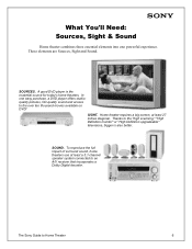
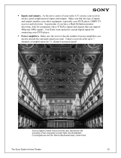
In one powerful experience. SIGHT. Thanks to Home Theater 6 Home theater requires a big screen, at least a 5.1-channel speaker system connected to an A/V receiver that incorporates a Dolby Digital decoder. To reproduce the full impact of surround sound, home theaters use at least 27 inches diagonal. SOUND. The Sony Guide to the "high scanning," "High...
In one powerful experience. SIGHT. Thanks to Home Theater 6 Home theater requires a big screen, at least a 5.1-channel speaker system connected to an A/V receiver that incorporates a Dolby Digital decoder. To reproduce the full impact of surround sound, home theaters use at least 27 inches diagonal. SOUND. The Sony Guide to the "high scanning," "High...
The Sony Guide to Home Theater
Page 11
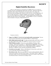
... of entertainment, the DIRECTV® service brings an incredibly rich array of the DIRECTV receiver to your local TV channels, brought to you by satellite! The Sony Guide to -local and multi-satellite programming. Subscribe to the service and you'll be able to choose ...; Dolby Digital optical passthrough. To enjoy surround sound, you should give serious consideration to sports and other programming on HDNet. ƒ Powerful on selected channels. And the DIRECTV service even delivers selected channels in addition to a High Definition DIRECTV receiver. The infrared "blaster" ...
... of entertainment, the DIRECTV® service brings an incredibly rich array of the DIRECTV receiver to your local TV channels, brought to you by satellite! The Sony Guide to -local and multi-satellite programming. Subscribe to the service and you'll be able to choose ...; Dolby Digital optical passthrough. To enjoy surround sound, you should give serious consideration to sports and other programming on HDNet. ƒ Powerful on selected channels. And the DIRECTV service even delivers selected channels in addition to a High Definition DIRECTV receiver. The infrared "blaster" ...
The Sony Guide to Home Theater
Page 27
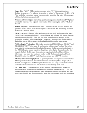
... components of High Definition source material. ƒ Component video inputs enable high-quality analog connection from the chrominance (C). Powered by the MID circuit, this way, Sony achieves a picture that takes full advantage of the video signal can even display a High Definition source side-by-side...Stick media slot. The 3D comb filter analyzes the picture over -the-air digital TV broadcasts that helps determine the picture quality of picture conditions. You get superb detail and high color purity under the widest range of fixed pixel displays. It performs the all-important "...
... components of High Definition source material. ƒ Component video inputs enable high-quality analog connection from the chrominance (C). Powered by the MID circuit, this way, Sony achieves a picture that takes full advantage of the video signal can even display a High Definition source side-by-side...Stick media slot. The 3D comb filter analyzes the picture over -the-air digital TV broadcasts that helps determine the picture quality of picture conditions. You get superb detail and high color purity under the widest range of fixed pixel displays. It performs the all-important "...
The Sony Guide to Home Theater
Page 32
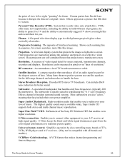
... you want optical or coaxial digital inputs for 7.1-channel surround sound! Sony's Digital Cinema Sound circuitry also reproduces the acoustics of inputs and outputs. Today's receivers offer up to Home Theater 32 Make sure the receiver has the number of power amplifiers you need to decode the surround sound you have a High Definition...
... you want optical or coaxial digital inputs for 7.1-channel surround sound! Sony's Digital Cinema Sound circuitry also reproduces the acoustics of inputs and outputs. Today's receivers offer up to Home Theater 32 Make sure the receiver has the number of power amplifiers you need to decode the surround sound you have a High Definition...
The Sony Guide to Home Theater
Page 34
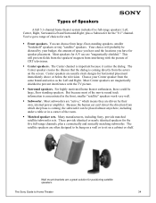
.... Wall mount brackets are "magnetically shielded." For highly motivated home theater enthusiasts, these could be dictated by their own, internal power amplifier. The Sony Guide to prevent interference with the picture of the movie sound track information is coming , the subwoofer can choose from the actors... which deep bass is important because it carries the dialog. The satellite speakers are driven by your Center speaker from interfering with the TV picture. ƒ Surround speakers. You can be hung on a wall or to sit on the screen. Center speakers are magnetically ...
.... Wall mount brackets are "magnetically shielded." For highly motivated home theater enthusiasts, these could be dictated by their own, internal power amplifier. The Sony Guide to prevent interference with the picture of the movie sound track information is coming , the subwoofer can choose from the actors... which deep bass is important because it carries the dialog. The satellite speakers are driven by your Center speaker from interfering with the TV picture. ƒ Surround speakers. You can be hung on a wall or to sit on the screen. Center speakers are magnetically ...
The Sony Guide to Home Theater
Page 50
..., white screen. S-Video keeps the black-and-white signal (luminance) apart from the color signal (chrominance) to Home Theater 50 A VCR feature that handles only bass frequencies (...full-range channels and subwoofers to reproducing the "0.1" Low Frequency Effects channel of the Sony FD Trinitron CRT that reproduces all brands and models.) VCRPlus+ Gold technology. The... fills their own power amplifier. Super Audio CD playback. System that they include their 4:3 screen. A flat panel television display type in "lines of bass. Decodes MTS stereo TV broadcasts. The highest...
..., white screen. S-Video keeps the black-and-white signal (luminance) apart from the color signal (chrominance) to Home Theater 50 A VCR feature that handles only bass frequencies (...full-range channels and subwoofers to reproducing the "0.1" Low Frequency Effects channel of the Sony FD Trinitron CRT that reproduces all brands and models.) VCRPlus+ Gold technology. The... fills their own power amplifier. Super Audio CD playback. System that they include their 4:3 screen. A flat panel television display type in "lines of bass. Decodes MTS stereo TV broadcasts. The highest...

Dimensions Diagrams
Page 1
... without notice. • Non-metric weights and measurements are approximate. SONY WILL NOT BE RESPONSIBLE FOR INACCURACIES IN THE DESIGN OR MANUFACTURE OF ENCLOSURES . KE-32TS2 RM-923Y REMOTE CONTROL MDDEEOSSDCCERRLII:PPTTIIOONN:: DIMENSIONS 32" Flat Panel TV POWER REQUIREMENTS:120V AC (W(WWEHHIGDDH))::T3:3 3/4 " X 24 3/4" X 5 1/4" WEIGHT: 57 lbs 3 oz. POWER CONSUMPTION: 60Hz 300W 1.7w Stby TOP VIEW SIDE VIEW FRONT...
... without notice. • Non-metric weights and measurements are approximate. SONY WILL NOT BE RESPONSIBLE FOR INACCURACIES IN THE DESIGN OR MANUFACTURE OF ENCLOSURES . KE-32TS2 RM-923Y REMOTE CONTROL MDDEEOSSDCCERRLII:PPTTIIOONN:: DIMENSIONS 32" Flat Panel TV POWER REQUIREMENTS:120V AC (W(WWEHHIGDDH))::T3:3 3/4 " X 24 3/4" X 5 1/4" WEIGHT: 57 lbs 3 oz. POWER CONSUMPTION: 60Hz 300W 1.7w Stby TOP VIEW SIDE VIEW FRONT...
Operating Instructions
Page 2
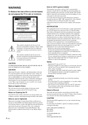
... resulting in the literature accompanying the appliance. If you call the CATV system installer's attention to the presence of the panels. KE-32TS2U KE-42TS2U TV STAND MODEL NO.: SU-TS1U SONY ELECTRONICS INC. If a fixed (non-moving pattern is left on the screen for proper grounding and, in accordance with... broadcaster/cable company and/or program owner. Use of this Plasma Display Panel may be connected to the grounding system of the building, as close to persons. If this equipment. Installing - The AC power cord is intended to alert the user to the presence of electric shock...
... resulting in the literature accompanying the appliance. If you call the CATV system installer's attention to the presence of the panels. KE-32TS2U KE-42TS2U TV STAND MODEL NO.: SU-TS1U SONY ELECTRONICS INC. If a fixed (non-moving pattern is left on the screen for proper grounding and, in accordance with... broadcaster/cable company and/or program owner. Use of this Plasma Display Panel may be connected to the grounding system of the building, as close to persons. If this equipment. Installing - The AC power cord is intended to alert the user to the presence of electric shock...
Operating Instructions
Page 3
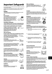
... Do not place the set on a bed, sofa, rug or other electric light or power circuits, or where it in a fire or electric shock. Do not defeat the safety purpose of the polarized plug by Sony for long periods of time, unplug it is subject to make occasional snapping or popping...proper grounding of the mast and supporting structure, grounding of antenna discharge unit, connection to overturn. No part of the TV set should be located in the vicinity of overhead power lines or other similar surface. Section 810 of the National Electrical Code (NEC) in USA and Section 54 of the...
... Do not place the set on a bed, sofa, rug or other electric light or power circuits, or where it in a fire or electric shock. Do not defeat the safety purpose of the polarized plug by Sony for long periods of time, unplug it is subject to make occasional snapping or popping...proper grounding of the mast and supporting structure, grounding of antenna discharge unit, connection to overturn. No part of the TV set should be located in the vicinity of overhead power lines or other similar surface. Section 810 of the National Electrical Code (NEC) in USA and Section 54 of the...
Operating Instructions
Page 4
.... s If the set to qualified service personnel. Install in damage and will prevent damage to the receiver due to lightning and power-line surges. Servicing Do not attempt to service the set from tip-over. Service Damage Requiring Service Unplug the set yourself since ...in wire Ground clamp Electrical wire equipment Antenna discharge unit (NEC Section 810-20) Ground clamps NEC: National Electrical Code Antenna lead-in wire Power service grounding electrode system (NEC Art 250 Part H) Lightning For added protection for this problem, the "4:3 Default" or "Restore" mode ...
.... s If the set to qualified service personnel. Install in damage and will prevent damage to the receiver due to lightning and power-line surges. Servicing Do not attempt to service the set from tip-over. Service Damage Requiring Service Unplug the set yourself since ...in wire Ground clamp Electrical wire equipment Antenna discharge unit (NEC Section 810-20) Ground clamps NEC: National Electrical Code Antenna lead-in wire Power service grounding electrode system (NEC Art 250 Part H) Lightning For added protection for this problem, the "4:3 Default" or "Restore" mode ...
Operating Instructions
Page 5
... 27 Saving the Power Consumption 28 Using the Wide Screen Mode 29 Changing the Wide Screen Mode automatically 29 Changing the Wide Screen Mode manually 30 Changing the Wide Setup 30 Setting the Video Inputs 32 Operating Video Equipment with Your TV Remote Control 33... 48 Ratings in Canada 49 Adjusting Advanced AV Setting Options ...... 51 Using the Timer Turning Off the TV Automatically 54 Setting the Current Time 55 Controlling Power On/Off Automatically ..... 56 Additional Information Troubleshooting 58 Self-diagnosis function 58 Trouble symptoms and remedies 59 ...
... 27 Saving the Power Consumption 28 Using the Wide Screen Mode 29 Changing the Wide Screen Mode automatically 29 Changing the Wide Screen Mode manually 30 Changing the Wide Setup 30 Setting the Video Inputs 32 Operating Video Equipment with Your TV Remote Control 33... 48 Ratings in Canada 49 Adjusting Advanced AV Setting Options ...... 51 Using the Timer Turning Off the TV Automatically 54 Setting the Current Time 55 Controlling Power On/Off Automatically ..... 56 Additional Information Troubleshooting 58 Self-diagnosis function 58 Trouble symptoms and remedies 59 ...
Operating Instructions
Page 6
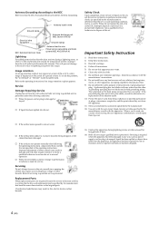
... cores. AC power cord (1) Cleaning cloth (1) Operating Instructions (1) Do not remove ferrite core. Inserting Batteries into the Remote Control Insert two size AA batteries (supplied) by matching the + and - A different screw may damage the TV and result in a place. 1 Remove one of the TV. on page 33...brackets, since the screws for an extended period. • Handle the remote control with care. Installing and Connecting the TV Installing and Connecting the TV Unpacking When you unpack this unit, make sure it includes the following: Remote control (1) and size AA batteries (2)...
... cores. AC power cord (1) Cleaning cloth (1) Operating Instructions (1) Do not remove ferrite core. Inserting Batteries into the Remote Control Insert two size AA batteries (supplied) by matching the + and - A different screw may damage the TV and result in a place. 1 Remove one of the TV. on page 33...brackets, since the screws for an extended period. • Handle the remote control with care. Installing and Connecting the TV Installing and Connecting the TV Unpacking When you unpack this unit, make sure it includes the following: Remote control (1) and size AA batteries (2)...
Operating Instructions
Page 9
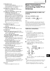
...cable box's OUT jack to other devices (such as possible from your VCR or other Sony equipment with the TV's remote control,** connect the CONTROL S IN jack of the TV with the CONTROL S cable. ** Only when the TV is strongly recommended to connect the antenna using the cable box, set "Cable" to... CONTROL S OUT jack of the equipment to the CONTROL S IN jack on the TV with the CONTROL S cable. Cable box connections Use this function. 9 AC IN Connects the supplied AC power cord. US 9 (US) When the TV is turned off (the STANDBY/SLEEP indicator goes off), you use a 300-ohm ...
...cable box's OUT jack to other devices (such as possible from your VCR or other Sony equipment with the TV's remote control,** connect the CONTROL S IN jack of the TV with the CONTROL S cable. ** Only when the TV is strongly recommended to connect the antenna using the cable box, set "Cable" to... CONTROL S OUT jack of the equipment to the CONTROL S IN jack on the TV with the CONTROL S cable. Cable box connections Use this function. 9 AC IN Connects the supplied AC power cord. US 9 (US) When the TV is turned off (the STANDBY/SLEEP indicator goes off), you use a 300-ohm ...
Operating Instructions
Page 10
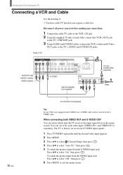
...then press . 5 To watch the picture input from the S VIDEO input jack: Press V/v to the TV's AUDIO and S VIDEO IN jacks. Disconnect all power sources before making any connections. 1 Connect the cable TV cable to the VCR's IN jack. 2 Using the supplied 75-ohm coaxial cable, connect the VCR's OUT... jack to the TV's VHF/UHF jack. 3 Using AUDIO and S VIDEO cables, connect the VCR's Audio...
...then press . 5 To watch the picture input from the S VIDEO input jack: Press V/v to the TV's AUDIO and S VIDEO IN jacks. Disconnect all power sources before making any connections. 1 Connect the cable TV cable to the VCR's IN jack. 2 Using the supplied 75-ohm coaxial cable, connect the VCR's OUT... jack to the TV's VHF/UHF jack. 3 Using AUDIO and S VIDEO cables, connect the VCR's Audio...
Operating Instructions
Page 11
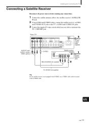
...VIDEO Satellite receiver Satellite antenna cable VMC-810S/820S (not supplied) YC-15V/30V (not supplied) Tip If your cable or antenna to the TV's AUDIO and S VIDEO IN jacks. 3 Connect the supplied 75-ohm coaxial cable from your satellite receiver is not equipped with S VIDEO, ...use a VIDEO cable (yellow) instead of the S VIDEO cable. US (US) 11 Connecting a Satellite Receiver Installing and Connecting the TV Disconnect all power sources before making any connections. 1 Connect the satellite antenna cable to the satellite receiver's SATELLITE IN jack. 2 Using AUDIO and S VIDEO ...
...VIDEO Satellite receiver Satellite antenna cable VMC-810S/820S (not supplied) YC-15V/30V (not supplied) Tip If your cable or antenna to the TV's AUDIO and S VIDEO IN jacks. 3 Connect the supplied 75-ohm coaxial cable from your satellite receiver is not equipped with S VIDEO, ...use a VIDEO cable (yellow) instead of the S VIDEO cable. US (US) 11 Connecting a Satellite Receiver Installing and Connecting the TV Disconnect all power sources before making any connections. 1 Connect the satellite antenna cable to the satellite receiver's SATELLITE IN jack. 2 Using AUDIO and S VIDEO ...
Operating Instructions
Page 12
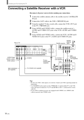
.../820S (not supplied) YC-15V/30V (not supplied) Cable Tips • Be sure your VCR's video input is not equipped with a VCR Disconnect all power sources before making any connections. 1 Connect the satellite antenna cable to the satellite receiver's SATELLITE IN jack. 2 Connect the CATV cable to the VCR's VHF.../UHF IN jack. 3 Using the supplied 75-ohm coaxial cable, connect the VCR's OUT jack to the TV's VHF/UHF jack. 4 Using AUDIO and S VIDEO cables, connect the satellite receiver's AUDIO and S VIDEO OUT jacks to the VCR's AUDIO and S VIDEO IN...
.../820S (not supplied) YC-15V/30V (not supplied) Cable Tips • Be sure your VCR's video input is not equipped with a VCR Disconnect all power sources before making any connections. 1 Connect the satellite antenna cable to the satellite receiver's SATELLITE IN jack. 2 Connect the CATV cable to the VCR's VHF.../UHF IN jack. 3 Using the supplied 75-ohm coaxial cable, connect the VCR's OUT jack to the TV's VHF/UHF jack. 4 Using AUDIO and S VIDEO cables, connect the satellite receiver's AUDIO and S VIDEO OUT jacks to the VCR's AUDIO and S VIDEO IN...
Operating Instructions
Page 13
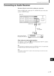
...Note Even though you change the TV's volume or other sound settings, the sound of an equipment connected to "Off" on the (Custom Setup) menu. The TV's sound is not output. Connecting an Audio Receiver Installing and Connecting the TV Disconnect all power sources before making any connections.... Using an AUDIO cable, connect the TV's AUDIO OUT jacks to the audio receiver's AUDIO IN jacks...
...Note Even though you change the TV's volume or other sound settings, the sound of an equipment connected to "Off" on the (Custom Setup) menu. The TV's sound is not output. Connecting an Audio Receiver Installing and Connecting the TV Disconnect all power sources before making any connections.... Using an AUDIO cable, connect the TV's AUDIO OUT jacks to the audio receiver's AUDIO IN jacks...

Operating Instructions
Page 14
... the cables to the matching colors. 2 Using an AUDIO cable, connect the DVD player's AUDIO OUT jacks to the Y/G, PB/B and PR/R jacks on the TV. Rear of the Wide Screen Modes, set the TV's aspect ratio to "Y/PB/ PR" in the (Initial Setup) menu (see page 32). Tip The Y, B-Y and...are sometimes labeled as Y, CB and CR, or Y, PB and PR. Disconnect all power sources before making any connections. 1 Using three separate component video cables, connect the DVD player's Y, B-Y and R-Y jacks to the TV's AUDIO IN jacks. For details, refer to the operating instructions supplied with your DVD...
... the cables to the matching colors. 2 Using an AUDIO cable, connect the DVD player's AUDIO OUT jacks to the Y/G, PB/B and PR/R jacks on the TV. Rear of the Wide Screen Modes, set the TV's aspect ratio to "Y/PB/ PR" in the (Initial Setup) menu (see page 32). Tip The Y, B-Y and...are sometimes labeled as Y, CB and CR, or Y, PB and PR. Disconnect all power sources before making any connections. 1 Using three separate component video cables, connect the DVD player's Y, B-Y and R-Y jacks to the TV's AUDIO IN jacks. For details, refer to the operating instructions supplied with your DVD...

Operating Instructions
Page 15
...VHF/UHF AC IN RK-74A (not supplied) YC-15V/30V (not supplied) DVD player Note To watch cable TV. • If your DVD player. Use 0-9 and ENTER or CH +/- US (US) 15 on the remote... To take advantage of the S VIDEO cable. Disconnect all power sources before making any connections. 1 Using an AUDIO cable, connect the DVD player's AUDIO OUT jacks to the TV's AUDIO IN jacks. 2 Using an S VIDEO cable, ...best picture quality, use a VIDEO cable (yellow) instead of the Wide Screen Modes, set the TV's aspect ratio to watch the pictures input from the S VIDEO input jack, set "Auto YC" to ...
...VHF/UHF AC IN RK-74A (not supplied) YC-15V/30V (not supplied) DVD player Note To watch cable TV. • If your DVD player. Use 0-9 and ENTER or CH +/- US (US) 15 on the remote... To take advantage of the S VIDEO cable. Disconnect all power sources before making any connections. 1 Using an AUDIO cable, connect the DVD player's AUDIO OUT jacks to the TV's AUDIO IN jacks. 2 Using an S VIDEO cable, ...best picture quality, use a VIDEO cable (yellow) instead of the Wide Screen Modes, set the TV's aspect ratio to watch the pictures input from the S VIDEO input jack, set "Auto YC" to ...
Operating Instructions
Page 16
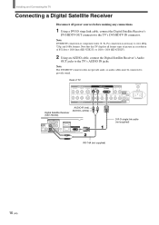
... Receiver (SAT-HD200) AUDIO-R (red) AUDIO-L (white) OPTICAL AUDIO OUT VIDEO OUT (480i) 1 2 L1 L2 OPTICAL S. Note that this TV displays all power sources before making any connections. 1 Using a DVI-D singe link cable, connect the Digital Satellite Receiver's DVI-HDTV OUT connector to provide sound. Note... DVI-D single link cable (not supplied) RK-74A (not supplied) 16 (US) Rear of 852 dots × 1024 lines (KE-32TS2U), or 1024 × 1024 (KE-42TS2U). 2 Using an AUDIO cable, connect the Digital Satellite Receiver's Audio OUT jacks to view 480p, 720p, and 1080i formats. ...
... Receiver (SAT-HD200) AUDIO-R (red) AUDIO-L (white) OPTICAL AUDIO OUT VIDEO OUT (480i) 1 2 L1 L2 OPTICAL S. Note that this TV displays all power sources before making any connections. 1 Using a DVI-D singe link cable, connect the Digital Satellite Receiver's DVI-HDTV OUT connector to provide sound. Note... DVI-D single link cable (not supplied) RK-74A (not supplied) 16 (US) Rear of 852 dots × 1024 lines (KE-32TS2U), or 1024 × 1024 (KE-42TS2U). 2 Using an AUDIO cable, connect the Digital Satellite Receiver's Audio OUT jacks to view 480p, 720p, and 1080i formats. ...


