Operating Instructions
Page 1
3-297-694-16(1) LCD Digital Color TV Operating Instructions KDL-32XBR6 KDL-40V4100 KDL-40W4100 KDL-37XBR6 KDL-42V4100 KDL-46W4100 KDL-40V4150 KDL-46V4100 KDL-52W4100 KDL-52V4100 KDL-46W4150 © 2008 Sony Corporation
3-297-694-16(1) LCD Digital Color TV Operating Instructions KDL-32XBR6 KDL-40V4100 KDL-40W4100 KDL-37XBR6 KDL-42V4100 KDL-46W4100 KDL-40V4150 KDL-46V4100 KDL-52W4100 KDL-52V4100 KDL-46W4150 © 2008 Sony Corporation
Operating Instructions
Page 2
... may cause instability and possibly result in the TV Guide On Screen system. Adobe is a trademark of Sony Corporation. KDL-32XBR6 KDL-37XBR6 KDL-40V4150 KDL-40V4100 KDL-40W4100 KDL-42V4100 KDL-46V4100 KDL-46W4100 KDL-46W4150 KDL-52V4100 KDL-52W4100 Sony Wall-Mount Bracket Model No. SU-FL71M - s Operate the TV only on the type of Sony Computer Entertainment Inc. This equipment generates, uses and can radiate...
... may cause instability and possibly result in the TV Guide On Screen system. Adobe is a trademark of Sony Corporation. KDL-32XBR6 KDL-37XBR6 KDL-40V4150 KDL-40V4100 KDL-40W4100 KDL-42V4100 KDL-46V4100 KDL-46W4100 KDL-46W4150 KDL-52V4100 KDL-52W4100 Sony Wall-Mount Bracket Model No. SU-FL71M - s Operate the TV only on the type of Sony Computer Entertainment Inc. This equipment generates, uses and can radiate...
Operating Instructions
Page 6
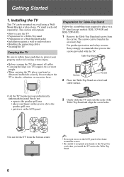
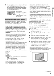
...holes. • Do not lift the TV from the carton. For product protection and safety reasons, Sony strongly recommends that you install the TV unit to not pinch your hands or the AC power cord when you use the screws provided with the TV. Preparation for a Wall-Mount Bracket •... for Table-Top Stand Follow the assembling steps required to place on a TV stand (except models: KDL-52V4100 and KDL-52W4100). 1 Remove the Table-Top Stand and screws from the bottom center. ~ • Do not put stress on the LCD panel or the frame around the screen. • Be careful to the...
...holes. • Do not lift the TV from the carton. For product protection and safety reasons, Sony strongly recommends that you install the TV unit to not pinch your hands or the AC power cord when you use the screws provided with the TV. Preparation for a Wall-Mount Bracket •... for Table-Top Stand Follow the assembling steps required to place on a TV stand (except models: KDL-52V4100 and KDL-52W4100). 1 Remove the Table-Top Stand and screws from the bottom center. ~ • Do not put stress on the LCD panel or the frame around the screen. • Be careful to the...
Operating Instructions
Page 7
... Mounting Hook. 4 Remove the screws on the rear of the KDL-52V4100 and KDL-52W4100 for Wall-Mount Bracket All models are removed, lift the TV off the stand. Models KDL-52V4100 and KDL-52W4100 will require detaching the Table-Top stand. • For product protection and safety reasons, Sony strongly recommends that they are 8 mm to 12 mm in...
... Mounting Hook. 4 Remove the screws on the rear of the KDL-52V4100 and KDL-52W4100 for Wall-Mount Bracket All models are removed, lift the TV off the stand. Models KDL-52V4100 and KDL-52W4100 will require detaching the Table-Top stand. • For product protection and safety reasons, Sony strongly recommends that they are 8 mm to 12 mm in...
Operating Instructions
Page 10
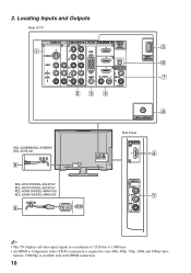
.../1080i/720p/480p/480i) 4 AUDIO OUT R AUDIO L L AUDIO R (VAR/FIX) 23 4 5 DMex/ SERVICE 6 7 KDL-32XBR6/KDL-37XBR6/ KDL-42V4100 9 KDL-40V4150/KDL-40V4100/ KDL-46V4100/KDL-52V4100/ KDL-40W4100/KDL-46W4100/ KDL-52W4100/KDL-46W4150 9 AC IN CABLE / ANTENNA 8 Side Panel IN 4 2 VIDEO IN 2 VIDEO L (MONO) AUDIO R 1 ~ • This TV displays all video input signals in a resolution of 1,920 dots × 1,080 lines. •...
.../1080i/720p/480p/480i) 4 AUDIO OUT R AUDIO L L AUDIO R (VAR/FIX) 23 4 5 DMex/ SERVICE 6 7 KDL-32XBR6/KDL-37XBR6/ KDL-42V4100 9 KDL-40V4150/KDL-40V4100/ KDL-46V4100/KDL-52V4100/ KDL-40W4100/KDL-46W4100/ KDL-52W4100/KDL-46W4150 9 AC IN CABLE / ANTENNA 8 Side Panel IN 4 2 VIDEO IN 2 VIDEO L (MONO) AUDIO R 1 ~ • This TV displays all video input signals in a resolution of 1,920 dots × 1,080 lines. •...
Operating Instructions
Page 46
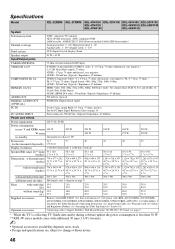
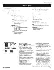
...KDL-37XBR6 KDL-40V4150 KDL-42V4100 KDL-46V4100 KDL-52V4100 KDL-40V4100 KDL-46W4100 KDL-52W4100 KDL-40W4100 KDL-46W4150 System Television system NTSC: American TV standard ATSC (8VSB terrestrial): ATSC compliant 8VSB QAM on cable: ANSI/SCTE 07 2000 (Does not include CableCARD functionality) Channel coverage Analog terrestrial: 2 - 69 / Digital terrestrial: 2 - 69 Analog Cable: 1 - 135 / Digital Cable: 1 - 135 Panel system LCD...While the TV is collecting TV Guide data and/or during software update the power consumption is less than 0.1 W* Screen size 31.5 37 40 42 46 52 (inches...
...KDL-37XBR6 KDL-40V4150 KDL-42V4100 KDL-46V4100 KDL-52V4100 KDL-40V4100 KDL-46W4100 KDL-52W4100 KDL-40W4100 KDL-46W4150 System Television system NTSC: American TV standard ATSC (8VSB terrestrial): ATSC compliant 8VSB QAM on cable: ANSI/SCTE 07 2000 (Does not include CableCARD functionality) Channel coverage Analog terrestrial: 2 - 69 / Digital terrestrial: 2 - 69 Analog Cable: 1 - 135 / Digital Cable: 1 - 135 Panel system LCD...While the TV is collecting TV Guide data and/or during software update the power consumption is less than 0.1 W* Screen size 31.5 37 40 42 46 52 (inches...
Service Manual
Page 1
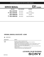
... include missing connectors. Updated 4-1. Replaced page 83 Updated 4-2. Replaced pages 88-112. HISTORY INFORMATION FOR THE FOLLOWING MANUAL: SERVICE MANUAL MODEL NAME REMOTE COMMANDER KDL-52V4100 ☛ KDL-52V4100 KDL-52W4100 ☛ KDL-52W4100 RM-YD023 RM-YD023 RM-YD023 RM-YD023 EX1 CHASSIS DESTINATION US/CND MX/LATIN AMERICA US/CND MX/LATIN AMERICA ORIGINAL MANUAL ISSUE.... Replaced pages 71, 73 and 75. Updated History Information page and Front Cover to include BU Board part numbers for Mexico and Latin America models. LCD DIGITAL COLOR TELEVISION 9-883-782-02
... include missing connectors. Updated 4-1. Replaced page 83 Updated 4-2. Replaced pages 88-112. HISTORY INFORMATION FOR THE FOLLOWING MANUAL: SERVICE MANUAL MODEL NAME REMOTE COMMANDER KDL-52V4100 ☛ KDL-52V4100 KDL-52W4100 ☛ KDL-52W4100 RM-YD023 RM-YD023 RM-YD023 RM-YD023 EX1 CHASSIS DESTINATION US/CND MX/LATIN AMERICA US/CND MX/LATIN AMERICA ORIGINAL MANUAL ISSUE.... Replaced pages 71, 73 and 75. Updated History Information page and Front Cover to include BU Board part numbers for Mexico and Latin America models. LCD DIGITAL COLOR TELEVISION 9-883-782-02
Service Manual
Page 3
...Legend 87 SECTION 5: ELECTRICAL PARTS LIST 88 APPENDIX A: ENCRYPTION KEY COMPONENTS A-1 KDL-52V4100/52W4100 3 Rear Cover Removal 13 1-2. LCD Panel Removal 17 1-10.Balancer (ETC-Inverter MT) Board Removal 18 WIRE DRESSING 19 KDL-52V4100 Only 19 KDL-52W4100 Only 35 SECTION 2: SERVICE ADJUSTMENTS 53 2-1. G5 Board (Power Unit) and... French 7 Safety-Related Component Warning 8 Safety Check-Out 10 Self-Diagnostic Function 11 SECTION 1: DISASSEMBLY 13 1-1. KDL-52V4100/52W4100 TABLE OF CONTENTS SECTION TITLE PAGE Specifications 4 Warnings and Cautions -
...Legend 87 SECTION 5: ELECTRICAL PARTS LIST 88 APPENDIX A: ENCRYPTION KEY COMPONENTS A-1 KDL-52V4100/52W4100 3 Rear Cover Removal 13 1-2. LCD Panel Removal 17 1-10.Balancer (ETC-Inverter MT) Board Removal 18 WIRE DRESSING 19 KDL-52V4100 Only 19 KDL-52W4100 Only 35 SECTION 2: SERVICE ADJUSTMENTS 53 2-1. G5 Board (Power Unit) and... French 7 Safety-Related Component Warning 8 Safety Check-Out 10 Self-Diagnostic Function 11 SECTION 1: DISASSEMBLY 13 1-1. KDL-52V4100/52W4100 TABLE OF CONTENTS SECTION TITLE PAGE Specifications 4 Warnings and Cautions -
Service Manual
Page 4
...jack, 500 mVrms 1kh Impedance: 47 kilohms Trademark Information KDL-52V4100/52W4100 Blu-ray Disc is protected by Gemstar-TV Guide International, Inc. The TV Guide On Screen system is a trademark of Sony Corporation. and/or its affiliates. Design and speci&#...TV Guide On Screen system and cannot guarantee service availability in connection with the accuracy or availability of Sony Corporation and Sony Computer Entertainment Inc. KDL-52V4100/52W4100 SPECIFICATIONS Power Requirements 120V AC, 60Hz Power Consumption (W) In Use (Max) 285W (KDL-52V4100 Only) 295W (KDL-52W4100...
...jack, 500 mVrms 1kh Impedance: 47 kilohms Trademark Information KDL-52V4100/52W4100 Blu-ray Disc is protected by Gemstar-TV Guide International, Inc. The TV Guide On Screen system is a trademark of Sony Corporation. and/or its affiliates. Design and speci&#...TV Guide On Screen system and cannot guarantee service availability in connection with the accuracy or availability of Sony Corporation and Sony Computer Entertainment Inc. KDL-52V4100/52W4100 SPECIFICATIONS Power Requirements 120V AC, 60Hz Power Consumption (W) In Use (Max) 285W (KDL-52V4100 Only) 295W (KDL-52W4100...
Service Manual
Page 5
...1-135 Cable Antenna 75-ohm external terminal for RF inputs Panel System LCD (Liquid Crystal Display) Panel Display Resolution (horizontal x vertical) 1,920 dots x 1,080 lines Screen Size (measured diagonally) ~ 52 inches Supplied Accessories Remote Commander RM-YD023 Two Size AA (R6) ...Booklet Attaching the Table-Top Stand Optional Accessories Connecting Cables Suport Belt Kit Wall-Mount Bracket SU-WL500 TV-Stand WS-S10LS SU-FL300/350L KDL-52V4100/52W4100 5 KDL-52V4100/52W4100 Speaker Output KDL-52V4100 KDL-52W4100 10W+10W mm in Dimensions (W x H x D) with stand mm in without stand mm ...
...1-135 Cable Antenna 75-ohm external terminal for RF inputs Panel System LCD (Liquid Crystal Display) Panel Display Resolution (horizontal x vertical) 1,920 dots x 1,080 lines Screen Size (measured diagonally) ~ 52 inches Supplied Accessories Remote Commander RM-YD023 Two Size AA (R6) ...Booklet Attaching the Table-Top Stand Optional Accessories Connecting Cables Suport Belt Kit Wall-Mount Bracket SU-WL500 TV-Stand WS-S10LS SU-FL300/350L KDL-52V4100/52W4100 5 KDL-52V4100/52W4100 Speaker Output KDL-52V4100 KDL-52W4100 10W+10W mm in Dimensions (W x H x D) with stand mm in without stand mm ...

Service Manual
Page 14
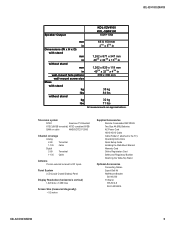
G5 BOARD (POWER UNIT) AND D4Z BOARD, AND D5 BOARD REMOVAL 1 Disconnect 3 connectors 2 Remove 4 screws 3 Disconnect 6 connectors (KDL-52V4100 ONLY) Disconnect 7 connectors (KDL-52W4100 ONLY) 4 Remove 6 screws 5 Release 5 Board Holders 6 Disconnect 5 connectors 7 Remove 4 screws 1 2 5 6 D5 Board 3 4 KDL-52V4100/52W4100 G5 Board (Power Unit) D4Z Board 7 14 1-3. SIDE JACK BRACKET, BU SHIELD AND BU BOARD REMOVAL 1 Release hook and...
G5 BOARD (POWER UNIT) AND D4Z BOARD, AND D5 BOARD REMOVAL 1 Disconnect 3 connectors 2 Remove 4 screws 3 Disconnect 6 connectors (KDL-52V4100 ONLY) Disconnect 7 connectors (KDL-52W4100 ONLY) 4 Remove 6 screws 5 Release 5 Board Holders 6 Disconnect 5 connectors 7 Remove 4 screws 1 2 5 6 D5 Board 3 4 KDL-52V4100/52W4100 G5 Board (Power Unit) D4Z Board 7 14 1-3. SIDE JACK BRACKET, BU SHIELD AND BU BOARD REMOVAL 1 Release hook and...
Service Manual
Page 17
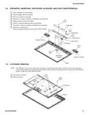
... hooks from Clear Panel 7 Disconnect 1 connector and Slide out H4 Board from Light Guide 8 Disconnect 1 connector and Remove Illumination Module from Bezel. (KDL-52W4100 ONLY) 1 Speaker Unit (L) 3 Under Bar 4 H3E Board 5 6 Clear Panel Light Guide 7 H4 Board 2 8 Illumination Module Speaker Unit (R)... is attached to Wire Dressing Illustration on Page 32 for KDL-52V4100 models or Page 50 for KDL-52W4100 models. 1 Disconnect 3 connectors 2 Remove 2 screws 1 2 LCD Panel Bezel KDL-52V4100/52W4100 17 Refer to the BU Board. LCD PANEL REMOVAL Bezel NOTE: The LVDS cable can only be...
... hooks from Clear Panel 7 Disconnect 1 connector and Slide out H4 Board from Light Guide 8 Disconnect 1 connector and Remove Illumination Module from Bezel. (KDL-52W4100 ONLY) 1 Speaker Unit (L) 3 Under Bar 4 H3E Board 5 6 Clear Panel Light Guide 7 H4 Board 2 8 Illumination Module Speaker Unit (R)... is attached to Wire Dressing Illustration on Page 32 for KDL-52V4100 models or Page 50 for KDL-52W4100 models. 1 Disconnect 3 connectors 2 Remove 2 screws 1 2 LCD Panel Bezel KDL-52V4100/52W4100 17 Refer to the BU Board. LCD PANEL REMOVAL Bezel NOTE: The LVDS cable can only be...
Service Manual
Page 35
KDL-52V4100/52W4100 35 Use Plastic Boss and "dimple" as guides where center of the panel. KDL-52W4100 ONLY H Boards / Speaker Harness Apply Sheet Core C over RED UL tape once harness is . KDL-52V4100/52W4100 LEGEND SHEET CORE C (2-688-011-01) QTY=12 LCD TAPE (2-688-062-01) QTY=4 SLIDE CLAMP (2-650-770-01) QTY=1 (UPPER VESA SUPPORT) SLIDE CLAMP (2-650-770-11) QTY=11 Center RED UL tape on the harness to the Center of panel is centered over panel.
KDL-52V4100/52W4100 35 Use Plastic Boss and "dimple" as guides where center of the panel. KDL-52W4100 ONLY H Boards / Speaker Harness Apply Sheet Core C over RED UL tape once harness is . KDL-52V4100/52W4100 LEGEND SHEET CORE C (2-688-011-01) QTY=12 LCD TAPE (2-688-062-01) QTY=4 SLIDE CLAMP (2-650-770-01) QTY=1 (UPPER VESA SUPPORT) SLIDE CLAMP (2-650-770-11) QTY=11 Center RED UL tape on the harness to the Center of panel is centered over panel.
Service Manual
Page 37
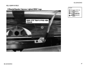
KDL-52W4100 ONLY H Boards/Speaker Harness: Lighted SONY Logo Apply LCD Tape to sharp edge of panel. 1 KDL-52V4100/52W4100 LEGEND SHEET CORE C (2-688-011-01) QTY=12 LCD TAPE (2-688-062-01) QTY=4 SLIDE CLAMP (2-650-770-01) QTY=1 (UPPER VESA SUPPORT) SLIDE CLAMP (2-650-770-11) QTY=11 KDL-52V4100/52W4100 37
KDL-52W4100 ONLY H Boards/Speaker Harness: Lighted SONY Logo Apply LCD Tape to sharp edge of panel. 1 KDL-52V4100/52W4100 LEGEND SHEET CORE C (2-688-011-01) QTY=12 LCD TAPE (2-688-062-01) QTY=4 SLIDE CLAMP (2-650-770-01) QTY=1 (UPPER VESA SUPPORT) SLIDE CLAMP (2-650-770-11) QTY=11 KDL-52V4100/52W4100 37
Service Manual
Page 39
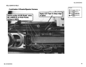
BE CAREFUL of Pinch Points (circled in RED) Apply LCD Tape to sharp edge of H3E Board wires. KDL-52W4100 ONLY Combination H Boards/Speaker Harness NOTE routing of panel. 2 KDL-52V4100/52W4100 LEGEND SHEET CORE C (2-688-011-01) QTY=12 LCD TAPE (2-688-062-01) QTY=4 SLIDE CLAMP (2-650-770-01) QTY=1 (UPPER VESA SUPPORT) SLIDE CLAMP (2-650-770-11) QTY=11 KDL-52V4100/52W4100 39
BE CAREFUL of Pinch Points (circled in RED) Apply LCD Tape to sharp edge of H3E Board wires. KDL-52W4100 ONLY Combination H Boards/Speaker Harness NOTE routing of panel. 2 KDL-52V4100/52W4100 LEGEND SHEET CORE C (2-688-011-01) QTY=12 LCD TAPE (2-688-062-01) QTY=4 SLIDE CLAMP (2-650-770-01) QTY=1 (UPPER VESA SUPPORT) SLIDE CLAMP (2-650-770-11) QTY=11 KDL-52V4100/52W4100 39

Service Manual
Page 41
Wire are ABOVE plastic CLIP on the connector assy as shown. KDL-52W4100 ONLY Balancer Board to G5 Board 9P Conn Assy. KDL-52V4100/52W4100 LEGEND SHEET CORE C (2-688-011-01) QTY=12 LCD TAPE (2-688-062-01) QTY=4 SLIDE CLAMP (2-650-770-01) QTY=1 (UPPER VESA SUPPORT) SLIDE CLAMP (2-650-770-11) QTY=11 8 6 7 NOTE DETAIL PHOTO of Conn Assy. KDL-52V4100/52W4100 41 Apply x3 Sheet Core C himelon tape 8 as guide where To place himelon tape. Use BLACK UL TAPE on panel.
Wire are ABOVE plastic CLIP on the connector assy as shown. KDL-52W4100 ONLY Balancer Board to G5 Board 9P Conn Assy. KDL-52V4100/52W4100 LEGEND SHEET CORE C (2-688-011-01) QTY=12 LCD TAPE (2-688-062-01) QTY=4 SLIDE CLAMP (2-650-770-01) QTY=1 (UPPER VESA SUPPORT) SLIDE CLAMP (2-650-770-11) QTY=11 8 6 7 NOTE DETAIL PHOTO of Conn Assy. KDL-52V4100/52W4100 41 Apply x3 Sheet Core C himelon tape 8 as guide where To place himelon tape. Use BLACK UL TAPE on panel.

Service Manual
Page 42
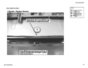
Wires CANNOT be clear of this Plastic pin (pinch point). KDL-52V4100/52W4100 LEGEND SHEET CORE C (2-688-011-01) QTY=12 LCD TAPE (2-688-062-01) QTY=4 SLIDE CLAMP (2-650-770-01) QTY=1 (UPPER VESA SUPPORT) SLIDE CLAMP (2-650-770-11) QTY=11 8 With Lower LCD Bracket installed, Wires will be below level of metal edge as shown if Black UL Tape is Aligned with white plastic pin (as guide for Black UL Tape position. Detail Use Plastic Pin as shown) KDL-52V4100/52W4100 42 Apply Sheet Core C to secure wires. KDL-52W4100 ONLY Panel Balancer Board Conn Assy.
Wires CANNOT be clear of this Plastic pin (pinch point). KDL-52V4100/52W4100 LEGEND SHEET CORE C (2-688-011-01) QTY=12 LCD TAPE (2-688-062-01) QTY=4 SLIDE CLAMP (2-650-770-01) QTY=1 (UPPER VESA SUPPORT) SLIDE CLAMP (2-650-770-11) QTY=11 8 With Lower LCD Bracket installed, Wires will be below level of metal edge as shown if Black UL Tape is Aligned with white plastic pin (as guide for Black UL Tape position. Detail Use Plastic Pin as shown) KDL-52V4100/52W4100 42 Apply Sheet Core C to secure wires. KDL-52W4100 ONLY Panel Balancer Board Conn Assy.

Service Manual
Page 43
NO NEED to Left Speaker wires. KDL-52W4100 ONLY LEFT Speaker Harness 5 5 Apply LCD Tape to put LCD Tape on Speaker 3 Dress Speaker wires and Main Harness In Slide Clamp KDL-52V4100/52W4100 LEGEND SHEET CORE C (2-688-011-01) QTY=12 LCD TAPE (2-688-062-01) QTY=4 SLIDE CLAMP (2-650-770-01) QTY=1 (UPPER VESA SUPPORT) SLIDE CLAMP (2-650-770-11) QTY=11 KDL-52V4100/52W4100 43
NO NEED to Left Speaker wires. KDL-52W4100 ONLY LEFT Speaker Harness 5 5 Apply LCD Tape to put LCD Tape on Speaker 3 Dress Speaker wires and Main Harness In Slide Clamp KDL-52V4100/52W4100 LEGEND SHEET CORE C (2-688-011-01) QTY=12 LCD TAPE (2-688-062-01) QTY=4 SLIDE CLAMP (2-650-770-01) QTY=1 (UPPER VESA SUPPORT) SLIDE CLAMP (2-650-770-11) QTY=11 KDL-52V4100/52W4100 43

Service Manual
Page 45
KDL-52V4100/52W4100 LEGEND SHEET CORE C (2-688-011-01) QTY=12 LCD TAPE (2-688-062-01) QTY=4 SLIDE CLAMP (2-650-770-01) QTY=1 (UPPER VESA SUPPORT) SLIDE CLAMP (2-650-770-11) QTY=11 KDL-52V4100/52W4100 45 KDL-52W4100 ONLY Balancer Board Wire Dressing 9 6 NEW Hirose MDF-61 Connector on both balancer boards.
KDL-52V4100/52W4100 LEGEND SHEET CORE C (2-688-011-01) QTY=12 LCD TAPE (2-688-062-01) QTY=4 SLIDE CLAMP (2-650-770-01) QTY=1 (UPPER VESA SUPPORT) SLIDE CLAMP (2-650-770-11) QTY=11 KDL-52V4100/52W4100 45 KDL-52W4100 ONLY Balancer Board Wire Dressing 9 6 NEW Hirose MDF-61 Connector on both balancer boards.

Service Manual
Page 46
STEP4: PULL LOCK BLACK LOCK TAB IN DIRECTION INDICATED ON PWB TO LOCK CONNECTOR. "HRS" LOGO WILL BE VISIBLE WHEN CONNECTOR IS PROPERLY LOCKED. WHEN CONNECTOR IS SEATED IT WILL "CLICK" INTO PLACE. KDL-52W4100 ONLY INSTALLATION PROCEDURE FOR MDF-61 CONNECTOR KDL-52V4100/52W4100 LEGEND SHEET CORE C (2-688-011-01) QTY=12 LCD TAPE (2-688-062-01) QTY=4 SLIDE CLAMP (2-650-770-01) QTY=1 (UPPER VESA SUPPORT) SLIDE CLAMP (2-650-770-11) QTY=11 STEP1: ALIGN CONNECTOR STEP2: INSTALL CONNECTOR STEP3: PUSH DOWN ON BLACK LOCK TAB TO SEAT CONNECTOR. KDL-52V4100/52W4100 46
STEP4: PULL LOCK BLACK LOCK TAB IN DIRECTION INDICATED ON PWB TO LOCK CONNECTOR. "HRS" LOGO WILL BE VISIBLE WHEN CONNECTOR IS PROPERLY LOCKED. WHEN CONNECTOR IS SEATED IT WILL "CLICK" INTO PLACE. KDL-52W4100 ONLY INSTALLATION PROCEDURE FOR MDF-61 CONNECTOR KDL-52V4100/52W4100 LEGEND SHEET CORE C (2-688-011-01) QTY=12 LCD TAPE (2-688-062-01) QTY=4 SLIDE CLAMP (2-650-770-01) QTY=1 (UPPER VESA SUPPORT) SLIDE CLAMP (2-650-770-11) QTY=11 STEP1: ALIGN CONNECTOR STEP2: INSTALL CONNECTOR STEP3: PUSH DOWN ON BLACK LOCK TAB TO SEAT CONNECTOR. KDL-52V4100/52W4100 46


