Operating Instructions
Page 2
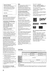
...cannot guarantee service availability in connection with Canadian ICES-003. CAUTION Use the following WALL-MOUNT BRACKET or TV-stand. SU-WL500 Sony TV - CAUTION To prevent electric shock and blade exposure, do not use this manual could void your ... from Dolby Laboratories. Declaration of Conformity Trade Name: SONY Model: KDL-32XBR6/KDL-37XBR6/ KDL-40V4150/KDL-40V4100/ KDL-42V4100/KDL-46V4100/ KDL-52V4100/KDL-40W4100/ KDL-46W4100/KDL-52W4100/ KDL-46W4150 Responsible Party: Sony Electronics Inc. In the United States, TV Guide and other outlet unless the blades can be ...
...cannot guarantee service availability in connection with Canadian ICES-003. CAUTION Use the following WALL-MOUNT BRACKET or TV-stand. SU-WL500 Sony TV - CAUTION To prevent electric shock and blade exposure, do not use this manual could void your ... from Dolby Laboratories. Declaration of Conformity Trade Name: SONY Model: KDL-32XBR6/KDL-37XBR6/ KDL-40V4150/KDL-40V4100/ KDL-42V4100/KDL-46V4100/ KDL-52V4100/KDL-40W4100/ KDL-46W4100/KDL-52W4100/ KDL-46W4150 Responsible Party: Sony Electronics Inc. In the United States, TV Guide and other outlet unless the blades can be ...
Operating Instructions
Page 3
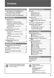
... 12 HD Cable Box/HD Satellite Box 12 PC 14 Other Equipment 15 4. Installing the TV 6 Carrying the TV 6 Preparation for Table-Top Stand 6 Preparation for HDMI 25 How to Use TV Guide On Screen 26 Using P&P and PIP Features 28 To Enter P&P and PIP 28 ...variety of BRAVIA® The Four Steps to the World of optional equipment connection diagrams. Customer Support http://www.sony.com/tvsupport Canada http://www.sony.ca/support On-line Registration United States http://productregistration.sony.com Canada http://www.sonystyle.ca/registration 3 Locating Inputs and Outputs 10 3.
... 12 HD Cable Box/HD Satellite Box 12 PC 14 Other Equipment 15 4. Installing the TV 6 Carrying the TV 6 Preparation for Table-Top Stand 6 Preparation for HDMI 25 How to Use TV Guide On Screen 26 Using P&P and PIP Features 28 To Enter P&P and PIP 28 ...variety of BRAVIA® The Four Steps to the World of optional equipment connection diagrams. Customer Support http://www.sony.com/tvsupport Canada http://www.sony.ca/support On-line Registration United States http://productregistration.sony.com Canada http://www.sonystyle.ca/registration 3 Locating Inputs and Outputs 10 3.
Operating Instructions
Page 6
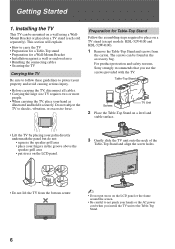
... a TV stand (each sold separately). Installing the TV This TV can be mounted on a wall using a WallMount Bracket or placed on a TV stand (except models: KDL-52V4100 and KDL-52W4100). 1 Remove the Table-Top Stand and screws from the bottom center. ~ • Do not put stress on the LCD panel. 3 Gently slide the TV unit...pinch your hands or the AC power cord when you use the screws provided with the TV. For product protection and safety reasons, Sony strongly recommends that you install the TV unit to shocks, vibration, or excessive force. The screws can be found in the groove...
... a TV stand (each sold separately). Installing the TV This TV can be mounted on a wall using a WallMount Bracket or placed on a TV stand (except models: KDL-52V4100 and KDL-52W4100). 1 Remove the Table-Top Stand and screws from the bottom center. ~ • Do not put stress on the LCD panel. 3 Gently slide the TV unit...pinch your hands or the AC power cord when you use the screws provided with the TV. For product protection and safety reasons, Sony strongly recommends that you install the TV unit to shocks, vibration, or excessive force. The screws can be found in the groove...
Operating Instructions
Page 7
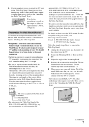
... diameter and length of the wall for Wall-Mount Bracket All models are removed, lift the TV off the stand. Do not attempt to lift the TV by a Sony dealer or licensed contractor. • Sufficient expertise is model KDL-52V4100; other models may result in the next column). Getting Started 4 Use the supplied screws to attach...
... diameter and length of the wall for Wall-Mount Bracket All models are removed, lift the TV off the stand. Do not attempt to lift the TV by a Sony dealer or licensed contractor. • Sufficient expertise is model KDL-52V4100; other models may result in the next column). Getting Started 4 Use the supplied screws to attach...
Operating Instructions
Page 8
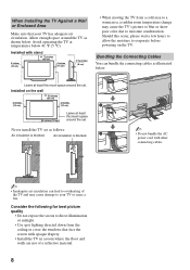
... to direct illumination or sunlight. • Use spot lighting directed down from the ceiling or cover the windows that your TV or cause a fire. Should this much space around the set . Installed with stand 11 7/8 inches (30 cm) 4 inches (10 cm) 4 inches (10 cm) 2 3/8 inches (6 cm) ...• When moving the TV from a cold area to a warm area, a sudden room temperature change may cause damage to evaporate before powering ...
... to direct illumination or sunlight. • Use spot lighting directed down from the ceiling or cover the windows that your TV or cause a fire. Should this much space around the set . Installed with stand 11 7/8 inches (30 cm) 4 inches (10 cm) 4 inches (10 cm) 2 3/8 inches (6 cm) ...• When moving the TV from a cold area to a warm area, a sudden room temperature change may cause damage to evaporate before powering ...
Operating Instructions
Page 9
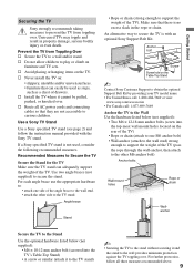
... to the wall stud) strong enough to the TV stand. An alternative way to secure the stand. For further protection, follow the instruction manual provided with an optional Sony Support Belt Kit. s Install the TV where it and the stand to play or climb on the TV. Use a Sony TV Stand Use a Sony specified TV stand (see page 2) and follow all AC power...
... to the wall stud) strong enough to the TV stand. An alternative way to secure the stand. For further protection, follow the instruction manual provided with an optional Sony Support Belt Kit. s Install the TV where it and the stand to play or climb on the TV. Use a Sony TV Stand Use a Sony specified TV stand (see page 2) and follow all AC power...
Operating Instructions
Page 46
... cord (KDL-40V4150/KDL-40V4100/KDL46V4100/KDL-52V4100/KDL-40W4100/KDL-46W4100/KDL-52W4100/KDL-46W4150) (1) / Cable holder (1 attached to the Table-Top Stand) / Operating Instructions (1) / Quick Setup Guide (1) / Warranty Card (1) / Safety and Regulatory Booklet (1) / Attaching the Table-Top Stand (1) / Screws (4) Optional accessories Connecting cables / Support Belt Kit / Wall-Mount Bracket: SU-WL500 / TV Stand: see page 2 * While the TV is collecting TV Guide...
... cord (KDL-40V4150/KDL-40V4100/KDL46V4100/KDL-52V4100/KDL-40W4100/KDL-46W4100/KDL-52W4100/KDL-46W4150) (1) / Cable holder (1 attached to the Table-Top Stand) / Operating Instructions (1) / Quick Setup Guide (1) / Warranty Card (1) / Safety and Regulatory Booklet (1) / Attaching the Table-Top Stand (1) / Screws (4) Optional accessories Connecting cables / Support Belt Kit / Wall-Mount Bracket: SU-WL500 / TV Stand: see page 2 * While the TV is collecting TV Guide...
Service Manual
Page 1
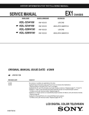
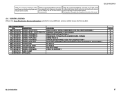
Replaced pages 88-112. LCD DIGITAL COLOR TELEVISION 9-883-782-02 Updated History Information page and Front Cover to include missing connectors. Updated 4-1. Updated D4Z, D5, and G5 schematics to include other destinations. Rear Cover Assembly and Stand Assembly section to include label part... for Mexico and Latin America models. HISTORY INFORMATION FOR THE FOLLOWING MANUAL: SERVICE MANUAL MODEL NAME REMOTE COMMANDER KDL-52V4100 ☛ KDL-52V4100 KDL-52W4100 ☛ KDL-52W4100 RM-YD023 RM-YD023 RM-YD023 RM-YD023 EX1 CHASSIS DESTINATION US/CND MX/LATIN AMERICA US/CND ...
Replaced pages 88-112. LCD DIGITAL COLOR TELEVISION 9-883-782-02 Updated History Information page and Front Cover to include missing connectors. Updated 4-1. Updated D4Z, D5, and G5 schematics to include other destinations. Rear Cover Assembly and Stand Assembly section to include label part... for Mexico and Latin America models. HISTORY INFORMATION FOR THE FOLLOWING MANUAL: SERVICE MANUAL MODEL NAME REMOTE COMMANDER KDL-52V4100 ☛ KDL-52V4100 KDL-52W4100 ☛ KDL-52W4100 RM-YD023 RM-YD023 RM-YD023 RM-YD023 EX1 CHASSIS DESTINATION US/CND MX/LATIN AMERICA US/CND ...
Service Manual
Page 3
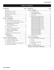
... COMPONENTS A-1 KDL-52V4100/52W4100 3 Speakers, Under Bar, H3E Board, H4 Board, and Light Guide Removal 17 1-9. Viewing Service Adjustment Data 53 2-2. Viewing the Service Menus 53 2-4. Rear Cover Assembly and Stand Assembly 83 4-2. English 6 Warnings and Cautions - Stand and Under ...Schematic Diagrams Information 55 3-3. Semiconductors 82 SECTION 4: EXPLODED VIEWS 83 4-1. LCD Panel Removal 17 1-10.Balancer (ETC-Inverter MT) Board Removal 18 WIRE DRESSING 19 KDL-52V4100 Only 19 KDL-52W4100 Only 35 SECTION 2: SERVICE ADJUSTMENTS 53 2-1. Switch Unit Removal (Contains...
... COMPONENTS A-1 KDL-52V4100/52W4100 3 Speakers, Under Bar, H3E Board, H4 Board, and Light Guide Removal 17 1-9. Viewing Service Adjustment Data 53 2-2. Viewing the Service Menus 53 2-4. Rear Cover Assembly and Stand Assembly 83 4-2. English 6 Warnings and Cautions - Stand and Under ...Schematic Diagrams Information 55 3-3. Semiconductors 82 SECTION 4: EXPLODED VIEWS 83 4-1. LCD Panel Removal 17 1-10.Balancer (ETC-Inverter MT) Board Removal 18 WIRE DRESSING 19 KDL-52V4100 Only 19 KDL-52W4100 Only 35 SECTION 2: SERVICE ADJUSTMENTS 53 2-1. Switch Unit Removal (Contains...
Service Manual
Page 5
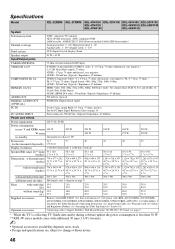
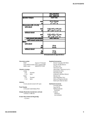
...1-135 Cable Antenna 75-ohm external terminal for RF inputs Panel System LCD (Liquid Crystal Display) Panel Display Resolution (horizontal x vertical) 1,920 dots x 1,080 lines Screen Size (measured diagonally) ~ 52 inches Supplied Accessories Remote Commander RM-YD023 Two Size AA (R6) ... TV) Operating Instructions Quick Setup Guide Installing the Wall-Mount Bracket Warranty Card Online Registration Card Safety and Regulatory Booklet Attaching the Table-Top Stand Optional Accessories Connecting Cables Suport Belt Kit Wall-Mount Bracket SU-WL500 TV-Stand WS-S10LS SU-FL300/350L KDL-52V4100/...
...1-135 Cable Antenna 75-ohm external terminal for RF inputs Panel System LCD (Liquid Crystal Display) Panel Display Resolution (horizontal x vertical) 1,920 dots x 1,080 lines Screen Size (measured diagonally) ~ 52 inches Supplied Accessories Remote Commander RM-YD023 Two Size AA (R6) ... TV) Operating Instructions Quick Setup Guide Installing the Wall-Mount Bracket Warranty Card Online Registration Card Safety and Regulatory Booklet Attaching the Table-Top Stand Optional Accessories Connecting Cables Suport Belt Kit Wall-Mount Bracket SU-WL500 TV-Stand WS-S10LS SU-FL300/350L KDL-52V4100/...

Service Manual
Page 15
AC INLET REMOVAL 1 Remove 2 screws 2 Remove 1 screw 2 AC Bracket AC Inlet 1 Bottom Bracket KDL-52V4100/52W4100 15 STAND AND UNDER COVER REMOVAL 1 Remove 4 screws 2 Remove 1 screw 1 Under Cover KDL-52V4100/52W4100 Stand Assembly 2 1-6. 1-5.
AC INLET REMOVAL 1 Remove 2 screws 2 Remove 1 screw 2 AC Bracket AC Inlet 1 Bottom Bracket KDL-52V4100/52W4100 15 STAND AND UNDER COVER REMOVAL 1 Remove 4 screws 2 Remove 1 screw 1 Under Cover KDL-52V4100/52W4100 Stand Assembly 2 1-6. 1-5.
Service Manual
Page 83
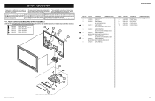
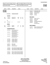
...290-844-01 8 3-295-631-01 9 3-290-843-01 10 3-290-842-01 DESCRIPTION STAND ASSY (LL) COVER, USER (LL) FOOT (15X20) COVER, NECK (LL) COVER, STAND (LL) [ASSEMBLY INCLUDES] [7-10] 5 6 7 8 9 10 KDL-52V4100/52W4100 83 NOTE: The components identified by a part number or description are not ... (Check the Sony Electronics Service Information website for any additional service related issues for safety. PART NO. 1 3-290-838-01 2 3-297-324-01 3 3-298-457-02 ☛3 3-298-457-11 DESCRIPTION [ASSEMBLY INCLUDES] COVER, REAR (52) COVER, ECS LABEL, TERMINAL (US AND CND MODELS ...
...290-844-01 8 3-295-631-01 9 3-290-843-01 10 3-290-842-01 DESCRIPTION STAND ASSY (LL) COVER, USER (LL) FOOT (15X20) COVER, NECK (LL) COVER, STAND (LL) [ASSEMBLY INCLUDES] [7-10] 5 6 7 8 9 10 KDL-52V4100/52W4100 83 NOTE: The components identified by a part number or description are not ... (Check the Sony Electronics Service Information website for any additional service related issues for safety. PART NO. 1 3-290-838-01 2 3-297-324-01 3 3-298-457-02 ☛3 3-298-457-11 DESCRIPTION [ASSEMBLY INCLUDES] COVER, REAR (52) COVER, ECS LABEL, TERMINAL (US AND CND MODELS ...
Service Manual
Page 87
...2-650-770-11 SLIDE, CLAMP 2-688-062-01 TAPE (LCD) LOCATION REAR COVER-21 SPINE-2 UNDER BAR-2 LCD-PNL-2 BOTTOM FRAME-4 TERMINAL-2 MIAN BRKT-1 LIGHT GUIDE-1 REAR COVER-6 STAND TO PNL-4 STAND NECK-7 STAND PLATE-4 UNDER COVER-1 SPINE-2 STAND PLATE-14 SPINE-8 CENTER FRAME-2 VESA TOP-2 VESA BOTTOM...repaired and/or replaced. Replace only with part number specified. KDL-52V4100/52W4100 4-5. Ne les remplacer que par une piece portant le numero specifie. SCREW LEGEND (Check the Sony Electronics Service Information website for any additional service related issues for safety....
...2-650-770-11 SLIDE, CLAMP 2-688-062-01 TAPE (LCD) LOCATION REAR COVER-21 SPINE-2 UNDER BAR-2 LCD-PNL-2 BOTTOM FRAME-4 TERMINAL-2 MIAN BRKT-1 LIGHT GUIDE-1 REAR COVER-6 STAND TO PNL-4 STAND NECK-7 STAND PLATE-4 UNDER COVER-1 SPINE-2 STAND PLATE-14 SPINE-8 CENTER FRAME-2 VESA TOP-2 VESA BOTTOM...repaired and/or replaced. Replace only with part number specified. KDL-52V4100/52W4100 4-5. Ne les remplacer que par une piece portant le numero specifie. SCREW LEGEND (Check the Sony Electronics Service Information website for any additional service related issues for safety....
Service Manual
Page 112
...A-1552-258-A STAND ASSY (SVC) * 3-287-536-01 TRAY (52) * 3-876-042-01 TRAY (52) MISCELLANEOUS 2-580-645-01 SCREW, +KTP2 3X10 2-650-770-11 SLIDE, CLAMP 2-688-062-01 TAPE (LCD) 7-632-452-24 TAPE (NO.303) 18MMX35M YEL * 2-888-494-01 TAPE, EARTH (KDL-52V4100 ONLY) REMOTE COMMANDER... 1-480-617-11 9-885-117-43 REMOTE COMMANDER (RM-YD023) BATTERY COVER (RM-YD023) 9-883-782-02 KDL-52V4100/52W4100 Sony Corporation Sony Technology Center Technical Services ...
...A-1552-258-A STAND ASSY (SVC) * 3-287-536-01 TRAY (52) * 3-876-042-01 TRAY (52) MISCELLANEOUS 2-580-645-01 SCREW, +KTP2 3X10 2-650-770-11 SLIDE, CLAMP 2-688-062-01 TAPE (LCD) 7-632-452-24 TAPE (NO.303) 18MMX35M YEL * 2-888-494-01 TAPE, EARTH (KDL-52V4100 ONLY) REMOTE COMMANDER... 1-480-617-11 9-885-117-43 REMOTE COMMANDER (RM-YD023) BATTERY COVER (RM-YD023) 9-883-782-02 KDL-52V4100/52W4100 Sony Corporation Sony Technology Center Technical Services ...


