SU-PF1L Instruction Manual
Page 4
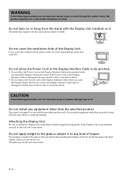
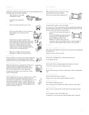
... injury or death. Do not lean on or hang from the stand with the Display Unit installed on the Power Cord or the Display Interface Cable when you cover the ventilation hole (with your hand when installing the Display Unit. Do not allow the Power Cord or the Display Interface... Cable to be pinched. • Do not allow the Power Cord or the Display Interface Cable to any equipment other than the specified product. CAUTION If the following precautions are not observed, injury or...
... injury or death. Do not lean on or hang from the stand with the Display Unit installed on the Power Cord or the Display Interface Cable when you cover the ventilation hole (with your hand when installing the Display Unit. Do not allow the Power Cord or the Display Interface... Cable to be pinched. • Do not allow the Power Cord or the Display Interface Cable to any equipment other than the specified product. CAUTION If the following precautions are not observed, injury or...
SU-PF1L Instruction Manual
Page 7
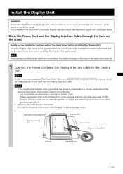
... speakers when carrying the Display Unit. - Rear side of Flat-Panel Color Television (KDE55XBR950/KDE61XBR950) for more details on the floor. on the floor and lay...speakers on the installation location and lay the stand down there before installing the Display Unit. When connecting cables to the Display Unit, place packing material, etc. Install the Display Unit WARNING If you allow the...between pieces of equipment, this , observe the following. - Draw the Power Cord and the Display Interface Cable through the hole on the stand. Note Do not push or pull the stand while it is on...
... speakers when carrying the Display Unit. - Rear side of Flat-Panel Color Television (KDE55XBR950/KDE61XBR950) for more details on the floor. on the floor and lay...speakers on the installation location and lay the stand down there before installing the Display Unit. When connecting cables to the Display Unit, place packing material, etc. Install the Display Unit WARNING If you allow the...between pieces of equipment, this , observe the following. - Draw the Power Cord and the Display Interface Cable through the hole on the stand. Note Do not push or pull the stand while it is on...
SU-PF1L Instruction Manual
Page 8
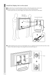
Rear side of the Display Unit Front side of the stand 2 1 3 Confirm that the hooks on the rear of the Display Unit are completely inserted into the holes on the stand beforehand. Then slide the Display Unit straight downward until it snaps on the fixtures. 2 Install the Display Unit on the stand. 1 Draw the Power Cord and the Display Interface Cable through the hole on the stand. 2 Check the position of the four holes on the fixtures on the fixtures of the stand. Hook 8 (US) Fit the hooks on the rear of the Display Unit into the four holes on .
Rear side of the Display Unit Front side of the stand 2 1 3 Confirm that the hooks on the rear of the Display Unit are completely inserted into the holes on the stand beforehand. Then slide the Display Unit straight downward until it snaps on the fixtures. 2 Install the Display Unit on the stand. 1 Draw the Power Cord and the Display Interface Cable through the hole on the stand. 2 Check the position of the four holes on the fixtures on the fixtures of the stand. Hook 8 (US) Fit the hooks on the rear of the Display Unit into the four holes on .
SU-PF1L Instruction Manual
Page 9
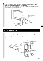
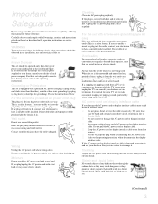
... drawn through the hole on the stand and take up the slack out of the cord and the cable. Pull the ends of the Power Cord and Display Interface Cable already drawn through the hole on the Display Unit. 2 Slide the fixing plate until the corner of the L-figure hits against the... screw. Power Cord and Display Interface Cable Fix the Display Unit Attach the fixing plate to prevent the Display Unit from falling. 1 Insert the fixing plate between the screw on the upper...
... drawn through the hole on the stand and take up the slack out of the cord and the cable. Pull the ends of the Power Cord and Display Interface Cable already drawn through the hole on the Display Unit. 2 Slide the fixing plate until the corner of the L-figure hits against the... screw. Power Cord and Display Interface Cable Fix the Display Unit Attach the fixing plate to prevent the Display Unit from falling. 1 Insert the fixing plate between the screw on the upper...
Marketing Specifications
Page 2
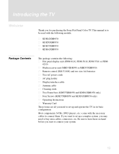
...8226; Cleaning Cloth Optional Accessories • Display Interface Cable VMC-P10 • Table Top Stand: SU-...Plasma Display Panel • Screen Size (Diagonally): KDE-42XBR950 = 42 inches KDE-50XBR950 = 50 inches KDE-55XBR950 = 55 inches KDE-61XBR950 = 61 inches • Display Resolution: KDE-42XBR950 = 1024 x 768 KDE-50XBR950 = 1365 x 768 KDE-55XBR950 = 1365 x 768 KDE...KDE-42/50/55/61XBR950 XBR® Plasma WEGA™ High Definition Television Sony Electronics Inc. 1 Sony Drive Park Ridge, NJ 07656 For more information: http://www.sony.com/dn Features Video • High Resolution Plasma...
...8226; Cleaning Cloth Optional Accessories • Display Interface Cable VMC-P10 • Table Top Stand: SU-...Plasma Display Panel • Screen Size (Diagonally): KDE-42XBR950 = 42 inches KDE-50XBR950 = 50 inches KDE-55XBR950 = 55 inches KDE-61XBR950 = 61 inches • Display Resolution: KDE-42XBR950 = 1024 x 768 KDE-50XBR950 = 1365 x 768 KDE-55XBR950 = 1365 x 768 KDE...KDE-42/50/55/61XBR950 XBR® Plasma WEGA™ High Definition Television Sony Electronics Inc. 1 Sony Drive Park Ridge, NJ 07656 For more information: http://www.sony.com/dn Features Video • High Resolution Plasma...
Operating Instructions
Page 3
...can be fully inserted to prevent blade exposure. s The plug is designed, for KDE55XBR950, this Plasma Display Panel may generate a low buzzing sound as a station logo is left on , the...installation. This symbol is connected. If this equipment does cause harmful interference to radio or television reception, which the receiver is intended to alert the user to the presence of electric ... details concerning safety precautions, see "Important Safeguards" on a circuit different from the broadcaster/cable company and/or program owner. WARNING To reduce the risk of fire or shock hazard,...
...can be fully inserted to prevent blade exposure. s The plug is designed, for KDE55XBR950, this Plasma Display Panel may generate a low buzzing sound as a station logo is left on , the...installation. This symbol is connected. If this equipment does cause harmful interference to radio or television reception, which the receiver is intended to alert the user to the presence of electric ... details concerning safety precautions, see "Important Safeguards" on a circuit different from the broadcaster/cable company and/or program owner. WARNING To reduce the risk of fire or shock hazard,...
Operating Instructions
Page 5
... interface cable If you are not sure of the type of power source indicated on the set through the cabinet slots as a precaution against injury, the following basic safety precautions should be operated only from the type of electrical power supplied to your home, consult your dealer or Sony service ...center to insert the plug fully into the outlet. Do not pull the AC power cord or display cable. Insert the plug fully into the outlet, try reversing the plug. When the set ...
... interface cable If you are not sure of the type of power source indicated on the set through the cabinet slots as a precaution against injury, the following basic safety precautions should be operated only from the type of electrical power supplied to your home, consult your dealer or Sony service ...center to insert the plug fully into the outlet. Do not pull the AC power cord or display cable. Insert the plug fully into the outlet, try reversing the plug. When the set ...
Operating Instructions
Page 9
... your foot or fingers. Be sure to the unit. Otherwise electric shock may damage the unit. Doing so may result in performance, it on the cables. Cable wiring Take care not to normal operation. s When the set exhibits a distinct change in damage and will often require extensive work by the manufacturer) to...
... your foot or fingers. Be sure to the unit. Otherwise electric shock may damage the unit. Doing so may result in performance, it on the cables. Cable wiring Take care not to normal operation. s When the set exhibits a distinct change in damage and will often require extensive work by the manufacturer) to...

Operating Instructions
Page 11
... TV 23 Detaching the speakers (KDE55XBR950 and KDE61XBR950 only 26 Basic Connections: Connecting a Cable or Antenna 28 Cable or Antenna 28 Cable Box and Cable 29 Cable Box 30 Connecting Optional Equipment 32 About Using S VIDEO 32 VCR and Cable 33 VCR and Cable Box 35 Two VCRs for Tape Editing 37 Satellite Receiver 39 Satellite Receiver...
... TV 23 Detaching the speakers (KDE55XBR950 and KDE61XBR950 only 26 Basic Connections: Connecting a Cable or Antenna 28 Cable or Antenna 28 Cable Box and Cable 29 Cable Box 30 Connecting Optional Equipment 32 About Using S VIDEO 32 VCR and Cable 33 VCR and Cable Box 35 Two VCRs for Tape Editing 37 Satellite Receiver 39 Satellite Receiver...
Operating Instructions
Page 12
Using the Remote Control Overview 55 Inserting Batteries 55 Button Descriptions 56 Programming the Remote Control 58 Using Other Equipment with Your Remote Control 61 All Equipment 61 Operating a VCR or D-VHS 61 Operating a Satellite Receiver 61 Operating a Cable Box 62 Operating a DVD Player 62 Operating an MDP (Laserdisc Player 62 Using the Features...
Using the Remote Control Overview 55 Inserting Batteries 55 Button Descriptions 56 Programming the Remote Control 58 Using Other Equipment with Your Remote Control 61 All Equipment 61 Operating a VCR or D-VHS 61 Operating a Satellite Receiver 61 Operating a Cable Box 62 Operating a DVD Player 62 Operating an MDP (Laserdisc Player 62 Using the Features...
Operating Instructions
Page 15
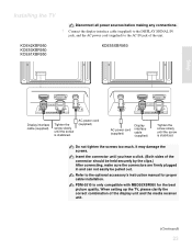
... your system. 13 If you want to set up a complex system, you start to buy extra cables, connectors, etc. This manual is to be used with the necessary cables to set up and operate the TV in its basic configuration. Be sure to have these on hand... unit (MBD-XBR950 or MBD55XBR950) s Remote control (RM-Y1000) and two size AA batteries s Two AC power cords s AC plug holder s Display interface cable s Antenna cable s Cleaning cloth s Two Frame bars (KDE55XBR950 and KDE61XBR950 only) s Four Screws (KDE55XBR950 and KDE61XBR950 only) s Operating Instructions s Warranty Card These items are ...
... your system. 13 If you want to set up a complex system, you start to buy extra cables, connectors, etc. This manual is to be used with the necessary cables to set up and operate the TV in its basic configuration. Be sure to have these on hand... unit (MBD-XBR950 or MBD55XBR950) s Remote control (RM-Y1000) and two size AA batteries s Two AC power cords s AC plug holder s Display interface cable s Antenna cable s Cleaning cloth s Two Frame bars (KDE55XBR950 and KDE61XBR950 only) s Four Screws (KDE55XBR950 and KDE61XBR950 only) s Operating Instructions s Warranty Card These items are ...

Operating Instructions
Page 19
Topic TV Controls and Connectors Installing the TV Basic Connections: Connecting a Cable or Antenna Connecting Optional Equipment About Using S VIDEO VCR and Cable VCR and Cable Box Two VCRs for setting up your TV. Setting Up the TV Overview This chapter includes illustrated instructions for Tape Editing Satellite Receiver Satellite Receiver ...
Topic TV Controls and Connectors Installing the TV Basic Connections: Connecting a Cable or Antenna Connecting Optional Equipment About Using S VIDEO VCR and Cable VCR and Cable Box Two VCRs for setting up your TV. Setting Up the TV Overview This chapter includes illustrated instructions for Tape Editing Satellite Receiver Satellite Receiver ...
Operating Instructions
Page 21
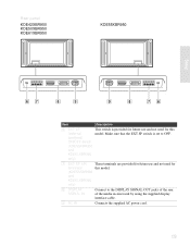
Rear panel KDE42XBR950 KDE50XBR950 KDE61XBR950 KDE55XBR950 Setup SONY EXCLUSIVE CABLE ONLY BLACK WHITE DISPLAY SIGNAL IN AC IN AC IN SONY EXCLUSIVE CABLE ONLY BLACK WHITE DISPLAY SIGNAL IN Item Description 6 EXT SP This switch is set to the DISPLAY SIGNAL OUT jacks of the rear of... the media receiver unit by using the supplied display interface cable. 9 AC IN Connects the supplied AC...
Rear panel KDE42XBR950 KDE50XBR950 KDE61XBR950 KDE55XBR950 Setup SONY EXCLUSIVE CABLE ONLY BLACK WHITE DISPLAY SIGNAL IN AC IN AC IN SONY EXCLUSIVE CABLE ONLY BLACK WHITE DISPLAY SIGNAL IN Item Description 6 EXT SP This switch is set to the DISPLAY SIGNAL OUT jacks of the rear of... the media receiver unit by using the supplied display interface cable. 9 AC IN Connects the supplied AC...
Operating Instructions
Page 24
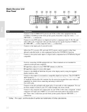
...listen to your sub woofer. (VAR) 4 CONTROL S IN/OUT Allows the TV to receive (IN) and send (OUT) remote control signals to other Sony infrared-controlled audio or video equipment that has S VIDEO. qs VIDEO IN 1/3 VIDEO/ L-AUDIO-R Connect to the S VIDEO OUT jack of the display ...) Connect to your TV's audio through your equipment for connection with personal computers. 7 VHF/UHF RF input that connects to your VHF/UHF antenna or cable box. 8 CABLE RF input that came with the TV. Setup Media Receiver Unit Rear Panel 1 2 34 5 67 8 S VIDEO VIDEO L (MONO) AUDIO R 1 VIDEO ...
...listen to your sub woofer. (VAR) 4 CONTROL S IN/OUT Allows the TV to receive (IN) and send (OUT) remote control signals to other Sony infrared-controlled audio or video equipment that has S VIDEO. qs VIDEO IN 1/3 VIDEO/ L-AUDIO-R Connect to the S VIDEO OUT jack of the display ...) Connect to your TV's audio through your equipment for connection with personal computers. 7 VHF/UHF RF input that connects to your VHF/UHF antenna or cable box. 8 CABLE RF input that came with the TV. Setup Media Receiver Unit Rear Panel 1 2 34 5 67 8 S VIDEO VIDEO L (MONO) AUDIO R 1 VIDEO ...
Operating Instructions
Page 25
KDE42XBR950 KDE50XBR950 KDE61XBR950 KDE55XBR950 Setup SONY EXCLUSIVE CABLE ONLY BLACK WHITE DISPLAY SIGNAL IN AC IN Display interface cable (supplied) Tighten the screw slowly until you hear a click. (Both sides of the connector should be held securely by the clips.)... be pulled out. Insert the connector until the screw is stabilized. AC power cord (supplied) AC IN SONY EXCLUSIVE CABLE ONLY BLACK WHITE DISPLAY SIGNAL IN AC power cord (supplied) Display interface cable (supplied) Tighten the screw slowly until the screw is only compatible with MBD55XBR950 for proper...
KDE42XBR950 KDE50XBR950 KDE61XBR950 KDE55XBR950 Setup SONY EXCLUSIVE CABLE ONLY BLACK WHITE DISPLAY SIGNAL IN AC IN Display interface cable (supplied) Tighten the screw slowly until you hear a click. (Both sides of the connector should be held securely by the clips.)... be pulled out. Insert the connector until the screw is stabilized. AC power cord (supplied) AC IN SONY EXCLUSIVE CABLE ONLY BLACK WHITE DISPLAY SIGNAL IN AC power cord (supplied) Display interface cable (supplied) Tighten the screw slowly until the screw is only compatible with MBD55XBR950 for proper...
Operating Instructions
Page 26
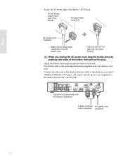
...'s AC IN jack. Setup 2 Secure the AC power plug to the media receiver unit's AC IN jack. L S400 (TS/DV/MICROMV) i.LINK VHF/UHF CABLE WHITE BLACK ~ AC IN DVI-HDTV DVI-HDTV IN 6 DISPLAY SIGNAL OUT Tighten the screw slowly until you unplug the AC power cord, drag the...) jack of the holder, then pull out the plug. 3 Install the display unit using an optional stand or rack unit. Display interface AC power cord cable (supplied) (supplied) 24 S VIDEO VIDEO L (MONO) AUDIO R 1 VIDEO IN HD/DVD IN (1080i/720p/480p/480i) Y Y SUB WOOFER OUT(VAR) AUDIO AUDIO PB L PB L ...
...'s AC IN jack. Setup 2 Secure the AC power plug to the media receiver unit's AC IN jack. L S400 (TS/DV/MICROMV) i.LINK VHF/UHF CABLE WHITE BLACK ~ AC IN DVI-HDTV DVI-HDTV IN 6 DISPLAY SIGNAL OUT Tighten the screw slowly until you unplug the AC power cord, drag the...) jack of the holder, then pull out the plug. 3 Install the display unit using an optional stand or rack unit. Display interface AC power cord cable (supplied) (supplied) 24 S VIDEO VIDEO L (MONO) AUDIO R 1 VIDEO IN HD/DVD IN (1080i/720p/480p/480i) Y Y SUB WOOFER OUT(VAR) AUDIO AUDIO PB L PB L ...
Operating Instructions
Page 27
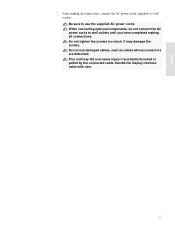
This unit may damage the screws. When connecting optional components, do not connect the AC power cords to wall outlets until you have completed making all connections. Setup 5 After making all connections, connect the AC power cords (supplied) to wall outlets. Handle the display interface cable with care. 25 It may fall and cause injury if accidently knocked or pulled by the connected cable. Do not tighten the screws too much. Be sure to use damaged cables, such as cables whose connectors are deformed. Do not use the supplied AC power cords.
This unit may damage the screws. When connecting optional components, do not connect the AC power cords to wall outlets until you have completed making all connections. Setup 5 After making all connections, connect the AC power cords (supplied) to wall outlets. Handle the display interface cable with care. 25 It may fall and cause injury if accidently knocked or pulled by the connected cable. Do not tighten the screws too much. Be sure to use damaged cables, such as cables whose connectors are deformed. Do not use the supplied AC power cords.

Operating Instructions
Page 30
...connect a VCR. Note on pages 33 and 35. Cable or Antenna For best results, use the supplied antenna cable. Cable Type VHF Only or combined VHF/UHF Connect As Shown Antenna cable (supplied) VHF/UHF Cable 75-ohm coaxial cable CABLE When using an indoor antenna, such as rabbit-ear...If You Are Connecting See Page Cable or Antenna 28 s No cable box or VCR Cable Box and Cable 29 s Cable box unscrambles only some channels (usually premium channels) s No VCR Cable Box 30 s Cable box unscrambles all channels s No VCR If you are connecting a cable or an antenna and you: ...
...connect a VCR. Note on pages 33 and 35. Cable or Antenna For best results, use the supplied antenna cable. Cable Type VHF Only or combined VHF/UHF Connect As Shown Antenna cable (supplied) VHF/UHF Cable 75-ohm coaxial cable CABLE When using an indoor antenna, such as rabbit-ear...If You Are Connecting See Page Cable or Antenna 28 s No cable box or VCR Cable Box and Cable 29 s Cable box unscrambles only some channels (usually premium channels) s No VCR Cable Box 30 s Cable box unscrambles all channels s No VCR If you are connecting a cable or an antenna and you: ...
Operating Instructions
Page 31
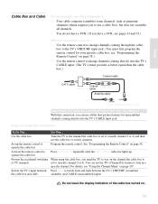
... must first program the remote control for unscrambled channels coming directly into the TV's CABLE input. (The TV's tuner provides a better signal than the cable box.) Coaxial cable CATV cable Splitter IN OUT Coaxial cable Cable Box Antenna cable CABLE VHF/UHF Rear of the cable box turned on page 107. see "Programming the Remote Control" on the channel...
... must first program the remote control for unscrambled channels coming directly into the TV's CABLE input. (The TV's tuner provides a better signal than the cable box.) Coaxial cable CATV cable Splitter IN OUT Coaxial cable Cable Box Antenna cable CABLE VHF/UHF Rear of the cable box turned on page 107. see "Programming the Remote Control" on the channel...

Operating Instructions
Page 32
....) With this connection you can: s Use the remote control to change channels coming through the cable box to the TV's VHF/UHF jack. (You must first program the remote control for your specific cable box, see page 58.) About Using This Connection with Dual Picture (Twin View, etc.) Features...through your channels are scrambled, but others are not, consider using the "Cable Box and Cable" connection on page 54. To connect the cable box 1 Connect the CATV cable to the cable box's input jack. 2 Use the supplied antenna cable to connect the cable box's output jack to the TV's VHF/UHF jack. 3 Run ...
....) With this connection you can: s Use the remote control to change channels coming through the cable box to the TV's VHF/UHF jack. (You must first program the remote control for your specific cable box, see page 58.) About Using This Connection with Dual Picture (Twin View, etc.) Features...through your channels are scrambled, but others are not, consider using the "Cable Box and Cable" connection on page 54. To connect the cable box 1 Connect the CATV cable to the cable box's input jack. 2 Use the supplied antenna cable to connect the cable box's output jack to the TV's VHF/UHF jack. 3 Run ...


