
Instructions (SU-PW3M Wall-Mount Bracket)
Page 1
2-179-718-12 (1) For Customers and Sony Dealers in North and Central America Wall-Mount Bracket Instructions US Mode d'emploi FR Instrucciones ES SU-PW3M © 2004 Sony Corporation
2-179-718-12 (1) For Customers and Sony Dealers in North and Central America Wall-Mount Bracket Instructions US Mode d'emploi FR Instrucciones ES SU-PW3M © 2004 Sony Corporation

Instructions (SU-PW3M Wall-Mount Bracket)
Page 2
...used incorrectly, it may result in possible damage to the customer after installation. For Sony dealers Sufficient expertise is capable of September 2004) Flat-panel Color Television KDE-37XS955 KDE-42XS955 KDE-50XS955 When installing the TV on . Please give this product. Use with safety in a serious injury through .... To Customers Sufficient expertise is not connected properly. Sony is not liable for installing this manual to the TV. (An error message will appear on the TV screen when turned on the Wall-Mount Bracket, make sure that the connector is used incorrectly...
...used incorrectly, it may result in possible damage to the customer after installation. For Sony dealers Sufficient expertise is capable of September 2004) Flat-panel Color Television KDE-37XS955 KDE-42XS955 KDE-50XS955 When installing the TV on . Please give this product. Use with safety in a serious injury through .... To Customers Sufficient expertise is not connected properly. Sony is not liable for installing this manual to the TV. (An error message will appear on the TV screen when turned on the Wall-Mount Bracket, make sure that the connector is used incorrectly...
Instructions (SU-PW3M Wall-Mount Bracket)
Page 3
...fall and cause injury or Do not disassemble or make alterations to the parts of the Wall- If you do so, the Wall-Mount US weight. (See the TV installing dimensions table on Bracket may fall and cause page 16 for use with a cloth, etc.), heat may fall and cause injury... cause a serious injury such as a Do not remove screws, etc., after mounting the TV. property damage. This Wall-Mount Bracket is designed for the weight of each TV.) injury or property damage. • If the installation of the Wall-Mount Bracket on the English wall is not sufficiently sturdy, the unit may fall...
...fall and cause injury or Do not disassemble or make alterations to the parts of the Wall- If you do so, the Wall-Mount US weight. (See the TV installing dimensions table on Bracket may fall and cause page 16 for use with a cloth, etc.), heat may fall and cause injury... cause a serious injury such as a Do not remove screws, etc., after mounting the TV. property damage. This Wall-Mount Bracket is designed for the weight of each TV.) injury or property damage. • If the installation of the Wall-Mount Bracket on the English wall is not sufficiently sturdy, the unit may fall...
Instructions (SU-PW3M Wall-Mount Bracket)
Page 4
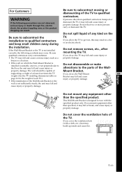
... the corners or the sides of the TV protrude away from the TV. If you and cause serious injury. Do not install the Wall-Mount Bracket on or hang from the wall surface. Do not expose the TV to hit the protruded corner or side of the TV, it may cause injury or property damage.... It may occur. candles) away from the TV. To prevent a fire, keep flammable objects or...
... the corners or the sides of the TV protrude away from the TV. If you and cause serious injury. Do not install the Wall-Mount Bracket on or hang from the wall surface. Do not expose the TV to hit the protruded corner or side of the TV, it may cause injury or property damage.... It may occur. candles) away from the TV. To prevent a fire, keep flammable objects or...

Instructions (SU-PW3M Wall-Mount Bracket)
Page 5
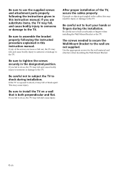
... For Sony Dealers WARNING To Sony Dealers The following the instructions in the speaker unit which generates magnetic influence. If any items that are left. • If you have routed 300-ohm feeder cables behind the wall, we recommend that you use the TV installed on the Wall-Mount Bracket for a .... Keep any of the screws are for Sony Dealers only. Be sure to read safety precautions described above the TV may become discolored or the wallpaper may come unstuck, depending on the material of the wall. • If the Wall-Mount Bracket is removed after installing it is necessary to ...
... For Sony Dealers WARNING To Sony Dealers The following the instructions in the speaker unit which generates magnetic influence. If any items that are left. • If you have routed 300-ohm feeder cables behind the wall, we recommend that you use the TV installed on the Wall-Mount Bracket for a .... Keep any of the screws are for Sony Dealers only. Be sure to read safety precautions described above the TV may become discolored or the wallpaper may come unstuck, depending on the material of the wall. • If the Wall-Mount Bracket is removed after installing it is necessary to ...
Instructions (SU-PW3M Wall-Mount Bracket)
Page 6
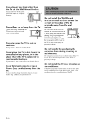
... given in this instruction manual. Be careful not to hurt your hands or fingers during installation. If the TV is both perpendicular and flat. If you use the supplied screws and attachment parts properly following the instructed procedure explained in this instruction manual.... After proper installation of the screws are not supplied. Be careful not to hurt your hands or fingers when installing the Wall-Mount Bracket or the TV...
... given in this instruction manual. Be careful not to hurt your hands or fingers during installation. If the TV is both perpendicular and flat. If you use the supplied screws and attachment parts properly following the instructed procedure explained in this instruction manual.... After proper installation of the screws are not supplied. Be careful not to hurt your hands or fingers when installing the Wall-Mount Bracket or the TV...

Instructions (SU-PW3M Wall-Mount Bracket)
Page 7
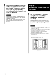
... (11 13⁄16) Plate Unit (1) Woofer Speaker 100 (3 15⁄16) Hook (4) 100 (3 15⁄16) 100 (3 15⁄16) Mounting Rack (1) Paper Template (1 set of the wall, beforehand. 2 Open the package and check the parts. The position for suitable clearance between the... TV and the ceiling and protruding parts of the paper template together with commercially available adhesive tape. Step 2: Decide on the installation location 1 Place the paper template on a perpendicular, flat wall and decide on page 17. For details,...
... (11 13⁄16) Plate Unit (1) Woofer Speaker 100 (3 15⁄16) Hook (4) 100 (3 15⁄16) 100 (3 15⁄16) Mounting Rack (1) Paper Template (1 set of the wall, beforehand. 2 Open the package and check the parts. The position for suitable clearance between the... TV and the ceiling and protruding parts of the paper template together with commercially available adhesive tape. Step 2: Decide on the installation location 1 Place the paper template on a perpendicular, flat wall and decide on page 17. For details,...
Instructions (SU-PW3M Wall-Mount Bracket)
Page 8
... 1 Fix the Plate Unit to the wall using four or more M8 (or equivalent) screws (not supplied). Select at least four times that of the TV (page 16). Step 3: Install the Plate Unit on . Reinforce the wall sufficiently, if necessary. Plate Unit 8 (US) Align the unit so that it is securely... securely so that they will not come loose. WARNING The wall that the Plate Unit is exactly level. WARNING • The screws securing the Wall-Mount Bracket to the wall are not supplied. • Be sure to use the appropriate screws, depending on the material and structure of the wall. •...
... 1 Fix the Plate Unit to the wall using four or more M8 (or equivalent) screws (not supplied). Select at least four times that of the TV (page 16). Step 3: Install the Plate Unit on . Reinforce the wall sufficiently, if necessary. Plate Unit 8 (US) Align the unit so that it is securely... securely so that they will not come loose. WARNING The wall that the Plate Unit is exactly level. WARNING • The screws securing the Wall-Mount Bracket to the wall are not supplied. • Be sure to use the appropriate screws, depending on the material and structure of the wall. •...
Instructions (SU-PW3M Wall-Mount Bracket)
Page 10
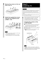
... be blocked resulting in a short circuit or an electric shock. Mount Bracket SU-PW3M, you may hurt yourself. 1 When installing a 50-inch TV on the Wall- Changing the position of the woofer speaker. ...1 Loosen the four screws (two on the rear side of the TV. 3 Remove four screws on ...using an electric screwdriver, set the torque setting to secure the woofer speaker. Step 5: Install the TV 4 Attach the supplied four hooks with the four supplied screws (+PSW5 × L14). WARNING Be ...
... be blocked resulting in a short circuit or an electric shock. Mount Bracket SU-PW3M, you may hurt yourself. 1 When installing a 50-inch TV on the Wall- Changing the position of the woofer speaker. ...1 Loosen the four screws (two on the rear side of the TV. 3 Remove four screws on ...using an electric screwdriver, set the torque setting to secure the woofer speaker. Step 5: Install the TV 4 Attach the supplied four hooks with the four supplied screws (+PSW5 × L14). WARNING Be ...
Instructions (SU-PW3M Wall-Mount Bracket)
Page 11
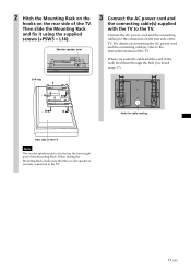
..., make sure that the woofer speaker is located on the lower right part of the TV. Hole for cable routing 11 (US) Then slide the Mounting Rack and fix it using the supplied screws (+PSW5 × L14). Woofer speaker joint 3 Connect the AC power cord and the connecting cable(s) ...supplied with the TV to the TV. 2 Hitch the Mounting Rack on the hooks on the rear side of the Mounting Rack. Soft rag Rear side of the TV Note The woofer speaker joint is securely connected to the...
..., make sure that the woofer speaker is located on the lower right part of the TV. Hole for cable routing 11 (US) Then slide the Mounting Rack and fix it using the supplied screws (+PSW5 × L14). Woofer speaker joint 3 Connect the AC power cord and the connecting cable(s) ...supplied with the TV to the TV. 2 Hitch the Mounting Rack on the hooks on the rear side of the Mounting Rack. Soft rag Rear side of the TV Note The woofer speaker joint is securely connected to the...
Instructions (SU-PW3M Wall-Mount Bracket)
Page 12
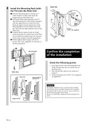
...(+B6 × L20, supplied) on either side touch the support braces of the Plate Unit. 2 Gradually lift the Mounting Rack and TV upward keeping the center notches engaged with the TV 1 Support brace Right side 4 Screws (+B6 × L20, supplied) Confirm the completion of the installation Check the ...following points. • Four upper hooks of the Mounting Rack are firmly hooked onto the two anchor bars of the Plate Unit....
...(+B6 × L20, supplied) on either side touch the support braces of the Plate Unit. 2 Gradually lift the Mounting Rack and TV upward keeping the center notches engaged with the TV 1 Support brace Right side 4 Screws (+B6 × L20, supplied) Confirm the completion of the installation Check the ...following points. • Four upper hooks of the Mounting Rack are firmly hooked onto the two anchor bars of the Plate Unit....
Instructions (SU-PW3M Wall-Mount Bracket)
Page 13
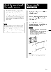
...to get hung up when removing the TV. • Be careful not to hurt your preference in woofer level setting from the wall outlet. 2 Remove all four securing screws secured in step 4 of the woofer speaker Remove the TV For Sony Dealers This Wall-Mount Bracket is too strong, adjust the sound... quality to remove the TV. Check the operation of procedure 4 on page 12. Note Depending on the power switch of the...
...to get hung up when removing the TV. • Be careful not to hurt your preference in woofer level setting from the wall outlet. 2 Remove all four securing screws secured in step 4 of the woofer speaker Remove the TV For Sony Dealers This Wall-Mount Bracket is too strong, adjust the sound... quality to remove the TV. Check the operation of procedure 4 on page 12. Note Depending on the power switch of the...

Instructions (SU-PW3M Wall-Mount Bracket)
Page 14
... Unfasten the screws tighten at the bottom of the Mounting Rack (page 12). 3 Hold the bottom left and right of the TV and gradually lift it upward. Connect the external equipment cables to the TV after installation For Customers, Sony Dealers 1 Tilt the TV upward. 1 Unplug the AC power cord. 2 Unfasten... the two securing screws at the outer sides of the bottom left and right hooks of the Mounting Rack in step 5 of procedure 1. 2 Hold...
... Unfasten the screws tighten at the bottom of the Mounting Rack (page 12). 3 Hold the bottom left and right of the TV and gradually lift it upward. Connect the external equipment cables to the TV after installation For Customers, Sony Dealers 1 Tilt the TV upward. 1 Unplug the AC power cord. 2 Unfasten... the two securing screws at the outer sides of the bottom left and right hooks of the Mounting Rack in step 5 of procedure 1. 2 Hold...

Instructions (SU-PW3M Wall-Mount Bracket)
Page 15
power 10 cm (2) 4 Ω 50 W 420 (16 17⁄32) 480 (18 29⁄32) 15 (US) PLATE UNIT 79 (3 1⁄8) ø 90 (3 5⁄8) 670 (26 3⁄8) MOUNTING RACK 505 (19 29⁄32)* 520 (20 1⁄2) 44 85.5 (1 3⁄4) (3 3⁄8) * When changing the position of the woofer speaker for installing a 50-inch TV: 590 (23 1/4) SPEAKER Speaker unit Impedance Max. Specifications Unit: mm (inches) Weight: 15.0 kg (33 lb 1 oz) Design and specifications are subject to change without notice.
power 10 cm (2) 4 Ω 50 W 420 (16 17⁄32) 480 (18 29⁄32) 15 (US) PLATE UNIT 79 (3 1⁄8) ø 90 (3 5⁄8) 670 (26 3⁄8) MOUNTING RACK 505 (19 29⁄32)* 520 (20 1⁄2) 44 85.5 (1 3⁄4) (3 3⁄8) * When changing the position of the woofer speaker for installing a 50-inch TV: 590 (23 1/4) SPEAKER Speaker unit Impedance Max. Specifications Unit: mm (inches) Weight: 15.0 kg (33 lb 1 oz) Design and specifications are subject to change without notice.
Instructions (SU-PW3M Wall-Mount Bracket)
Page 16
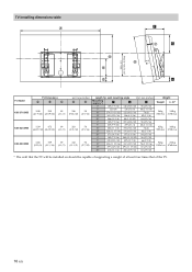
...; 5/256) F C G B H TV Model KDE-37XS955 KDE-42XS955 KDE-50XS955 TV Dimensions A B C 1048 599 89 (41 9/32) (23 19/32) (3 1/2) 1139 672 89 (44 27/32) (26 15/32) (3 1/2) 1336 789 89 (52 5/8) (31 1/16) (3 1/2) unit: mm (inches) D E 246 58 (9 23/32) (2 5/16) 283 58 (11 5/32) (2 5/16) 343 56 (13 1/2) (2 7/32) Length for each mounting angle Unit...
...; 5/256) F C G B H TV Model KDE-37XS955 KDE-42XS955 KDE-50XS955 TV Dimensions A B C 1048 599 89 (41 9/32) (23 19/32) (3 1/2) 1139 672 89 (44 27/32) (26 15/32) (3 1/2) 1336 789 89 (52 5/8) (31 1/16) (3 1/2) unit: mm (inches) D E 246 58 (9 23/32) (2 5/16) 283 58 (11 5/32) (2 5/16) 343 56 (13 1/2) (2 7/32) Length for each mounting angle Unit...

Operating Instructions
Page 4
... Wiring For your local cable operator. CAUTION Use the following SONY appliance(s) only with a wet hand, it may cause electric shock. 2 SONY APPLIANCE MODEL NO. KDE-37XS955 KDE-42XS955 KDE-50XS955 SONY WALL-MOUNT BRACKET MODEL NO. Licensed by forcing it is required to... read these instructions completely, and keep this manual for installing the specified product. BN Smoother is a trademark of Sony Corporation. This TV incorporates ...
... Wiring For your local cable operator. CAUTION Use the following SONY appliance(s) only with a wet hand, it may cause electric shock. 2 SONY APPLIANCE MODEL NO. KDE-37XS955 KDE-42XS955 KDE-50XS955 SONY WALL-MOUNT BRACKET MODEL NO. Licensed by forcing it is required to... read these instructions completely, and keep this manual for installing the specified product. BN Smoother is a trademark of Sony Corporation. This TV incorporates ...

Operating Instructions
Page 6
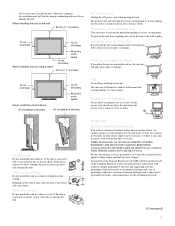
The screen glass may break by the clear plastic front panel. If you carry the TV in the following locations, injury may result. Watching the TV for some time after the TV is turned off. Optional accessories Observe the following : s Do not install the unit turned backward or sideways...temperature of the area where the set 's performance. Be sure to follow the instructions given below. s Carry the TV with your neighbors. Wall mount installation requires the use qualified contractors. s Be sure to follow the operating instructions supplied with the specified number of the...
The screen glass may break by the clear plastic front panel. If you carry the TV in the following locations, injury may result. Watching the TV for some time after the TV is turned off. Optional accessories Observe the following : s Do not install the unit turned backward or sideways...temperature of the area where the set 's performance. Be sure to follow the instructions given below. s Carry the TV with your neighbors. Wall mount installation requires the use qualified contractors. s Be sure to follow the operating instructions supplied with the specified number of the...
Operating Instructions
Page 7
... fire or electric shock. Preventing from toppling over and causing injury. If the unit is exposed to prevent the unit from the stand or wall-mount unit, causing damage or serious injury. Do not move the unit with the AC power cord plugged in a vehicle or hung from toppling over the...
... fire or electric shock. Preventing from toppling over and causing injury. If the unit is exposed to prevent the unit from the stand or wall-mount unit, causing damage or serious injury. Do not move the unit with the AC power cord plugged in a vehicle or hung from toppling over the...

Operating Instructions
Page 122
Other Info Optional Accessories s HDMI cable s Component video cable s S video cable s A/V cable s Audio cable s Optical cable s Control S cable: RK-G69 s Floating Stand: SU-PF3L (for KDE-50XS955) SU-PF3M (for KDE-37/42XS955) s Wall-Mount Bracket: SU-PW3M 120 Other Info
Other Info Optional Accessories s HDMI cable s Component video cable s S video cable s A/V cable s Audio cable s Optical cable s Control S cable: RK-G69 s Floating Stand: SU-PF3L (for KDE-50XS955) SU-PF3M (for KDE-37/42XS955) s Wall-Mount Bracket: SU-PW3M 120 Other Info

