
Instructions (SU-PW3M Wall-Mount Bracket)
Page 5
...using four or more M8 (or equivalent) screws. Do not allow the AC power cord or the connecting cable to the wall following instructions are susceptible to use the appropriate screws for Sony Dealers only. Keep any of this instruction manual. If any items that you ...strong magnet in this product. Be sure to 75ohm coaxial cables. Consult your contractor regarding an appropriate location (free from the TV speaker. If the AC power cord or the connecting cable is necessary to continue to safety during the installation, maintenance and checking of the screws are left...
...using four or more M8 (or equivalent) screws. Do not allow the AC power cord or the connecting cable to the wall following instructions are susceptible to use the appropriate screws for Sony Dealers only. Keep any of this instruction manual. If any items that you ...strong magnet in this product. Be sure to 75ohm coaxial cables. Consult your contractor regarding an appropriate location (free from the TV speaker. If the AC power cord or the connecting cable is necessary to continue to safety during the installation, maintenance and checking of the screws are left...
Instructions (SU-PW3M Wall-Mount Bracket)
Page 10
... a 50-inch TV on the rear side of the strut arms) used to slide the woofer speaker completely in step 2, the woofer speaker joint locating at the center bottom of the rear side of the TV and ... the position of the woofer speaker. 1 Loosen the four screws (two on each side of the TV. If you fail to secure the woofer speaker in place about three turns. 2 Slide the woofer speaker...blocked resulting in a short circuit or an electric shock. Be careful not to stumble over the AC power cord or the TV, as you need to change the position of equipment, this may occur to the wall outlet. ...
... a 50-inch TV on the rear side of the strut arms) used to slide the woofer speaker completely in step 2, the woofer speaker joint locating at the center bottom of the rear side of the TV and ... the position of the woofer speaker. 1 Loosen the four screws (two on each side of the TV. If you fail to secure the woofer speaker in place about three turns. 2 Slide the woofer speaker...blocked resulting in a short circuit or an electric shock. Be careful not to stumble over the AC power cord or the TV, as you need to change the position of equipment, this may occur to the wall outlet. ...
Instructions (SU-PW3M Wall-Mount Bracket)
Page 11
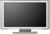
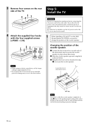
... the TV. For details on the lower right part of the Mounting Rack. When you route the cable and the cord in the wall, feed them through the hole you bored (page 17). When sliding the Mounting Rack, make sure that the woofer speaker is located on connecting the AC power cord... and the connecting cable(s), refer to the connectors on the rear side of the TV. Hole for cable routing 11 (US) Woofer speaker joint 3 Connect the AC power cord and the connecting cable(s) supplied with the TV to the TV. Connect the AC power cord and the connecting cable(s) to the instruction manual of the...
... the TV. For details on the lower right part of the Mounting Rack. When you route the cable and the cord in the wall, feed them through the hole you bored (page 17). When sliding the Mounting Rack, make sure that the woofer speaker is located on connecting the AC power cord... and the connecting cable(s), refer to the connectors on the rear side of the TV. Hole for cable routing 11 (US) Woofer speaker joint 3 Connect the AC power cord and the connecting cable(s) supplied with the TV to the TV. Connect the AC power cord and the connecting cable(s) to the instruction manual of the...
Instructions (SU-PW3M Wall-Mount Bracket)
Page 12
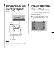
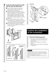
...AC power cord, etc., may cause the product falling and result in the center notches of the Mounting Rack. 4 Firmly tighten all four upper and lower screws (+B6 × L20, supplied) on either side touch the support braces of the Plate Unit. 2 Gradually lift the Mounting Rack and TV upward...Plate Unit and that the two center notches on each side of the Mounting Rack. 2 Mounting Rack 1 Side view Plate Unit 2 Mounting Rack with the TV 1 Support brace Right side 4 Screws (+B6 × L20, supplied) Confirm the completion of the installation Check the following points. • Four upper ...
...AC power cord, etc., may cause the product falling and result in the center notches of the Mounting Rack. 4 Firmly tighten all four upper and lower screws (+B6 × L20, supplied) on either side touch the support braces of the Plate Unit. 2 Gradually lift the Mounting Rack and TV upward...Plate Unit and that the two center notches on each side of the Mounting Rack. 2 Mounting Rack 1 Side view Plate Unit 2 Mounting Rack with the TV 1 Support brace Right side 4 Screws (+B6 × L20, supplied) Confirm the completion of the installation Check the following points. • Four upper ...
Instructions (SU-PW3M Wall-Mount Bracket)
Page 13
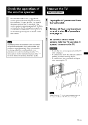
... Note Always hold the TV when carrying it upward to your hands or fingers when removing the TV. Note Depending on the TV screen after a while. 1 Unplug the AC power cord from the TV's menu option. Check the operation of the woofer speaker Remove the TV For Sony Dealers This Wall-Mount Bracket... is equipped with the TV) onto the Plate Unit, turn on the power switch of the TV ...
... Note Always hold the TV when carrying it upward to your hands or fingers when removing the TV. Note Depending on the TV screen after a while. 1 Unplug the AC power cord from the TV's menu option. Check the operation of the woofer speaker Remove the TV For Sony Dealers This Wall-Mount Bracket... is equipped with the TV) onto the Plate Unit, turn on the power switch of the TV ...

Instructions (SU-PW3M Wall-Mount Bracket)
Page 14
... bottom left and right hooks of the Mounting Rack. 5 Insert the screws removed in the AC power cord. Connect the external equipment cables to the TV after installation For Customers, Sony Dealers 1 Tilt the TV upward. 1 Unplug the AC power cord. 2 Unfasten the two securing screws at the outer sides of the bottom left and...
... bottom left and right hooks of the Mounting Rack. 5 Insert the screws removed in the AC power cord. Connect the external equipment cables to the TV after installation For Customers, Sony Dealers 1 Tilt the TV upward. 1 Unplug the AC power cord. 2 Unfasten the two securing screws at the outer sides of the bottom left and...

Instructions (SU-PW3M Wall-Mount Bracket)
Page 15
PLATE UNIT 79 (3 1⁄8) ø 90 (3 5⁄8) 670 (26 3⁄8) MOUNTING RACK 505 (19 29⁄32)* 520 (20 1⁄2) 44 85.5 (1 3⁄4) (3 3⁄8) * When changing the position of the woofer speaker for installing a 50-inch TV: 590 (23 1/4) SPEAKER Speaker unit Impedance Max. power 10 cm (2) 4 Ω 50 W 420 (16 17⁄32) 480 (18 29⁄32) 15 (US) Specifications Unit: mm (inches) Weight: 15.0 kg (33 lb 1 oz) Design and specifications are subject to change without notice.
PLATE UNIT 79 (3 1⁄8) ø 90 (3 5⁄8) 670 (26 3⁄8) MOUNTING RACK 505 (19 29⁄32)* 520 (20 1⁄2) 44 85.5 (1 3⁄4) (3 3⁄8) * When changing the position of the woofer speaker for installing a 50-inch TV: 590 (23 1/4) SPEAKER Speaker unit Impedance Max. power 10 cm (2) 4 Ω 50 W 420 (16 17⁄32) 480 (18 29⁄32) 15 (US) Specifications Unit: mm (inches) Weight: 15.0 kg (33 lb 1 oz) Design and specifications are subject to change without notice.

Operating Instructions
Page 3
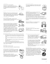
...of the National Electrical Code (NEC) that the cable ground shall be blurred or show poor color due to moisture condensation. This equipment generates, uses, and can radiate radio frequency energy and.... s Do not install the TV in a hot or humid place, or in wide screen mode (16:9 aspect ratio). When using the TV for several days, disconnect the power by qualified service personnel before turning... AC plug with an extension cord, receptacle or other than 800hPa), this Plasma Display Panel may require authorization from the ceiling or to cover the windows that a single image ...
...of the National Electrical Code (NEC) that the cable ground shall be blurred or show poor color due to moisture condensation. This equipment generates, uses, and can radiate radio frequency energy and.... s Do not install the TV in a hot or humid place, or in wide screen mode (16:9 aspect ratio). When using the TV for several days, disconnect the power by qualified service personnel before turning... AC plug with an extension cord, receptacle or other than 800hPa), this Plasma Display Panel may require authorization from the ceiling or to cover the windows that a single image ...

Operating Instructions
Page 4
... cable operator. If you are trademarks of Sony Corporation. Use with a polarized AC power cord plug (a plug having a third pin for grounding). SU-PF3L (for KDE-50XS955) SU-PF3M (for KDE-37/42XS955) To Customers Sufficient expertise is a trademark of Sony Corporation. BN Smoother is equipped with other ... the instructions supplied with a wet hand, it may cause instability and result in the operating instructions or service manual. This TV incorporates High-Definition Multimedia Interface (HDMI™) technology. Wall outlet Do not use and servicing of a set-top box. ...
... cable operator. If you are trademarks of Sony Corporation. Use with a polarized AC power cord plug (a plug having a third pin for grounding). SU-PF3L (for KDE-50XS955) SU-PF3M (for KDE-37/42XS955) To Customers Sufficient expertise is a trademark of Sony Corporation. BN Smoother is equipped with other ... the instructions supplied with a wet hand, it may cause instability and result in the operating instructions or service manual. This TV incorporates High-Definition Multimedia Interface (HDMI™) technology. Wall outlet Do not use and servicing of a set-top box. ...
Operating Instructions
Page 5
... is continuous or frequent while the TV is left unattended and unused for some TV sets to make occasional snapping or popping sounds, particularly when being used. AC power cord If you are unable to insert the plug into the outlet, contact your dealer or Sony service center to the unit. s Do ...not convert or damage the AC power cord or display interface...
... is continuous or frequent while the TV is left unattended and unused for some TV sets to make occasional snapping or popping sounds, particularly when being used. AC power cord If you are unable to insert the plug into the outlet, contact your dealer or Sony service center to the unit. s Do ...not convert or damage the AC power cord or display interface...

Operating Instructions
Page 6
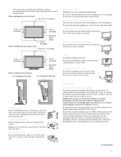
...TV at night time. s Do not install the unit in a location where the unit protrudes, such as a bookcase or built-in a confined space, such as pillars. Dust absorbing oil may result. s Do not install the unit turned over a radiator or heat register, or where it until you unplug the AC power... the wall by the clear plastic front panel. Volume adjustment Adjust the volume so as hearing damage may gather dust... to direct sunlight. 4 For proper ventilation, Observe the following when installing the TV using a stand or wall-mount bracket. s Be sure to excessive salt, ...
...TV at night time. s Do not install the unit in a location where the unit protrudes, such as a bookcase or built-in a confined space, such as pillars. Dust absorbing oil may result. s Do not install the unit turned over a radiator or heat register, or where it until you unplug the AC power... the wall by the clear plastic front panel. Volume adjustment Adjust the volume so as hearing damage may gather dust... to direct sunlight. 4 For proper ventilation, Observe the following when installing the TV using a stand or wall-mount bracket. s Be sure to excessive salt, ...
Operating Instructions
Page 7
... rain, it may heat up static charges. Outdoor use Do not install this much space. 30 cm (11 7/8 inches) AC power cord Unplug the AC power cord when moving the unit. An outdoor antenna system should not be blocked causing overheating and cause fire or damage the unit. Section... not install this unit in a ship or vessel. WHEN INSTALLING AN OUTDOOR ANTENNA SYSTEM, EXTREME CARE SHOULD BE TAKEN TO KEEP FROM CONTACTING SUCH POWER LINES OR CIRCUITS AS CONTACT WITH THEM IS ALMOST INVARIABLY FATAL. Air circulation is blocked. 10 cm (4 inches) Allow this unit outdoors. Otherwise,...
... rain, it may heat up static charges. Outdoor use Do not install this much space. 30 cm (11 7/8 inches) AC power cord Unplug the AC power cord when moving the unit. An outdoor antenna system should not be blocked causing overheating and cause fire or damage the unit. Section... not install this unit in a ship or vessel. WHEN INSTALLING AN OUTDOOR ANTENNA SYSTEM, EXTREME CARE SHOULD BE TAKEN TO KEEP FROM CONTACTING SUCH POWER LINES OR CIRCUITS AS CONTACT WITH THEM IS ALMOST INVARIABLY FATAL. Air circulation is blocked. 10 cm (4 inches) Allow this unit outdoors. Otherwise,...
Operating Instructions
Page 8
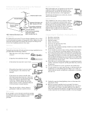
...other apparatus (including amplifiers) that are provided for your outlet, consult an electrician for replacement of the obsolete outlet. 10) Protect the power cord from being walked on or pinched particularly at plugs, convenience receptacles, and the point where they exit from tip-over. 13)... discharge unit (NEC Section 810-20) Grounding conductors (NEC Section 810-21) Ground clamps Power service grounding electrode system (NEC Art 250 Part H) Lightning For added protection for this TV receiver during lightning storms or when unused for long periods of time. 14) Refer all servicing...
...other apparatus (including amplifiers) that are provided for your outlet, consult an electrician for replacement of the obsolete outlet. 10) Protect the power cord from being walked on or pinched particularly at plugs, convenience receptacles, and the point where they exit from tip-over. 13)... discharge unit (NEC Section 810-20) Grounding conductors (NEC Section 810-21) Ground clamps Power service grounding electrode system (NEC Art 250 Part H) Lightning For added protection for this TV receiver during lightning storms or when unused for long periods of time. 14) Refer all servicing...
Operating Instructions
Page 9
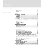
... 11 Package Contents 11 Features 12 Overview 15 TV Controls and Connectors 16 Front panel 16 Side panel 17 Rear panel 18 Connecting the Power Cord 20 Preventing the TV from Toppling Over 21 Bundling the Connecting Cables 22 Basic Connections: Connecting a Cable or Antenna 23 Cable or Antenna...CENTER SPEAKER IN Terminals 46 Camcorder 48 Audio Receiver 49 Sub Woofer 49 Device with an Optical (Digital Audio) Connector 50 Using the CONTROL S Feature 50 Using CableCARD 51 Activating CableCARD™ Service 51 Removing the CableCARD 52 Setting Up the Channel List 53 Using Auto ...
... 11 Package Contents 11 Features 12 Overview 15 TV Controls and Connectors 16 Front panel 16 Side panel 17 Rear panel 18 Connecting the Power Cord 20 Preventing the TV from Toppling Over 21 Bundling the Connecting Cables 22 Basic Connections: Connecting a Cable or Antenna 23 Cable or Antenna...CENTER SPEAKER IN Terminals 46 Camcorder 48 Audio Receiver 49 Sub Woofer 49 Device with an Optical (Digital Audio) Connector 50 Using the CONTROL S Feature 50 Using CableCARD 51 Activating CableCARD™ Service 51 Removing the CableCARD 52 Setting Up the Channel List 53 Using Auto ...

Operating Instructions
Page 13
...Most components (VCRs, DVD players, etc.) come with the following models: s KDE-37XS955 s KDE-42XS955 s KDE-50XS955 Package Contents The package contains the following: s Flat panel color TV s Remote control (RM-Y1004) and two size AA batteries s AC power cord s AC plug holder s Cable band (1) s Cable band screw (1) ...TV Welcome Thank you may need to connect your system. (Continued) 11 This manual is to be used with the necessary cables to set up and operate the TV in its basic configuration. If you want to set up a complex system, you for purchasing the Sony Flat Panel Color TV...
...Most components (VCRs, DVD players, etc.) come with the following models: s KDE-37XS955 s KDE-42XS955 s KDE-50XS955 Package Contents The package contains the following: s Flat panel color TV s Remote control (RM-Y1004) and two size AA batteries s AC power cord s AC plug holder s Cable band (1) s Cable band screw (1) ...TV Welcome Thank you may need to connect your system. (Continued) 11 This manual is to be used with the necessary cables to set up and operate the TV in its basic configuration. If you want to set up a complex system, you for purchasing the Sony Flat Panel Color TV...
Operating Instructions
Page 17
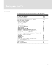
... and Connectors Connecting the Power Cord Basic Connections: Connecting a Cable or Antenna Connecting Optional Equipment Making Video Connections About Using S VIDEO VCR and Cable VCR and Cable Box Two VCRs for setting up your TV. Setting Up the TV Overview This chapter includes illustrated instructions for Tape Editing Satellite Receiver Satellite Receiver and... Up the Channel List Page(s) 16-19 20-22 23-27 28 29 30 32 34 36 38 41 43 44 46 48 49 49 50 50 51 53 15
... and Connectors Connecting the Power Cord Basic Connections: Connecting a Cable or Antenna Connecting Optional Equipment Making Video Connections About Using S VIDEO VCR and Cable VCR and Cable Box Two VCRs for setting up your TV. Setting Up the TV Overview This chapter includes illustrated instructions for Tape Editing Satellite Receiver Satellite Receiver and... Up the Channel List Page(s) 16-19 20-22 23-27 28 29 30 32 34 36 38 41 43 44 46 48 49 49 50 50 51 53 15
Operating Instructions
Page 18
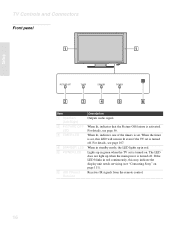
... feature is turned on page 111). Lights up in red continuously, this LED will remain lit even if the TV set , this may indicate the display unit needs servicing (see "Contacting Sony" on . When the timer is set is turned off . The LED does not light up in red..... For details, see page 56. When in standby mode, the LED lights up when the main power is turned off . Receives IR signals from the remote control. 16 TV Controls and Connectors Front panel Setup PICTURE OFF TIMER STANDBY POWER Item 1 Speakers (Left/Right) 2 PICTURE OFF LED 3 TIMER LED 4 STANDBY LED...
... feature is turned on page 111). Lights up in red continuously, this LED will remain lit even if the TV set , this may indicate the display unit needs servicing (see "Contacting Sony" on . When the timer is set is turned off . The LED does not light up in red..... For details, see page 56. When in standby mode, the LED lights up when the main power is turned off . Receives IR signals from the remote control. 16 TV Controls and Connectors Front panel Setup PICTURE OFF TIMER STANDBY POWER Item 1 Speakers (Left/Right) 2 PICTURE OFF LED 3 TIMER LED 4 STANDBY LED...
Operating Instructions
Page 19
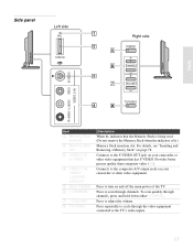
...to turn on page 78. Press repeatedly to cycle through the video equipment connected to adjust the volume. Setup Side panel Left side PRO STD/DUO Right side POWER CHANNEL VOLUME TV/VIDEO R AUDIO L(MONO) VIDEO S VIDEO VIDEO 2 IN Item 1 Memory Stick indicator 2 Memory Stick slot ...3 VIDEO 2 IN S VIDEO 4 VIDEO 2 IN VIDEO/ L (MONO)AUDIO-R 5 Main POWER 6 + CHANNEL - 7 + VOLUME - 8 TV/VIDEO Description When lit, indicates that has S VIDEO. Press to the composite A/V output jacks on your camcorder or other video equipment that the...
...to turn on page 78. Press repeatedly to cycle through the video equipment connected to adjust the volume. Setup Side panel Left side PRO STD/DUO Right side POWER CHANNEL VOLUME TV/VIDEO R AUDIO L(MONO) VIDEO S VIDEO VIDEO 2 IN Item 1 Memory Stick indicator 2 Memory Stick slot ...3 VIDEO 2 IN S VIDEO 4 VIDEO 2 IN VIDEO/ L (MONO)AUDIO-R 5 Main POWER 6 + CHANNEL - 7 + VOLUME - 8 TV/VIDEO Description When lit, indicates that has S VIDEO. Press to the composite A/V output jacks on your camcorder or other video equipment that the...
Operating Instructions
Page 20
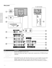
For more information, see page 51. 18 Rear panel AC IN OPTICAL OUT For KDE-50XS955 Setup CableCARD CableCARD R-AUDIO -L VIDEO IN VHF/UHF 6 CABLE 1 3 R-AUDIO -L (MONO) VIDEO S VIDEO 4 CENTER SPEAKER IN 180W (6 ) MAX CONTROL S IN OUT 5 R-AUDIO -L Y PB...OUT (VAR/FIX) SUBWOOFER OUT (VAR) Jack 1 AC IN 2 DIGITAL AUDIO (OPTICAL) OUT (PCM/DOLBY* DIGITAL) 3 CableCARD™ slot Description Connects the supplied AC power cord. Connect to the optical audio input of a digital audio component that will enable you to secure, digitally encrypted cable channels-without the need for...
For more information, see page 51. 18 Rear panel AC IN OPTICAL OUT For KDE-50XS955 Setup CableCARD CableCARD R-AUDIO -L VIDEO IN VHF/UHF 6 CABLE 1 3 R-AUDIO -L (MONO) VIDEO S VIDEO 4 CENTER SPEAKER IN 180W (6 ) MAX CONTROL S IN OUT 5 R-AUDIO -L Y PB...OUT (VAR/FIX) SUBWOOFER OUT (VAR) Jack 1 AC IN 2 DIGITAL AUDIO (OPTICAL) OUT (PCM/DOLBY* DIGITAL) 3 CableCARD™ slot Description Connects the supplied AC power cord. Connect to the optical audio input of a digital audio component that will enable you to secure, digitally encrypted cable channels-without the need for...

Operating Instructions
Page 22
...When you unplug the AC power cord, drag the holder down by pushing both sides of the holder, then pull out the plug. 3 Connect the other connections prior to connecting the power cord. 1 Connect the power cord to the AC IN connector of the TV. 2 Secure the AC power plug to the display's... AC IN jack. Setup Connecting the Power Cord Complete other end of the AC power cord (supplied) to a wall outlet. Do not use...
...When you unplug the AC power cord, drag the holder down by pushing both sides of the holder, then pull out the plug. 3 Connect the other connections prior to connecting the power cord. 1 Connect the power cord to the AC IN connector of the TV. 2 Secure the AC power plug to the display's... AC IN jack. Setup Connecting the Power Cord Complete other end of the AC power cord (supplied) to a wall outlet. Do not use...


