Operating Instructions
Page 6
...Adjusting the exposure manually ...... 65 Using the spot light-metering mode - Tape PB ZOOM 72 Searching for a scene - DATE SEARCH 79 Recording a picture 29 Editing Shooting a backlit subject Dubbing a tape 80 - BACK LIGHT 37 Recording video or TV programs ....... 83 Shooting in a "Memory Stick" on an image Operations - NightShot/ Superimposing a title 88 Super NightShot/Color Slow Making your own titles 94 Shutter 37 The micro Cassette Memory 97 Self-timer recording 40 Checking the recording "Memory Stick" Operations - Display function 43 Recording an image...
...Adjusting the exposure manually ...... 65 Using the spot light-metering mode - Tape PB ZOOM 72 Searching for a scene - DATE SEARCH 79 Recording a picture 29 Editing Shooting a backlit subject Dubbing a tape 80 - BACK LIGHT 37 Recording video or TV programs ....... 83 Shooting in a "Memory Stick" on an image Operations - NightShot/ Superimposing a title 88 Super NightShot/Color Slow Making your own titles 94 Shutter 37 The micro Cassette Memory 97 Self-timer recording 40 Checking the recording "Memory Stick" Operations - Display function 43 Recording an image...
Operating Instructions
Page 14
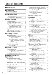
... need an NTSC system-based TV. IP220 MEMORY/NETWORK z z Provided - This format is indicated on a TV, you recorded and the next scene is the model used for illustration purposes. The mark is the same as a data compression method. Unauthorized recording of your recordings on the MICROMV cassette. Set the POWER switch to indicate that the operation is provided with all MICROMV cassettes. The DCR-IP220 is the still image. Any differences in operation...
... need an NTSC system-based TV. IP220 MEMORY/NETWORK z z Provided - This format is indicated on a TV, you recorded and the next scene is the model used for illustration purposes. The mark is the same as a data compression method. Unauthorized recording of your recordings on the MICROMV cassette. Set the POWER switch to indicate that the operation is provided with all MICROMV cassettes. The DCR-IP220 is the still image. Any differences in operation...
Operating Instructions
Page 46
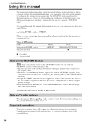
.... Connect the S video plug to LINE. Open the jack cover. Do not connect both of your TV. If you power your camcorder from a wall outlet using the S video plug to faithfully obtain original pictures. If your TV has an S video jack Connect using the AC power adaptor (p. 21). To turn off the LCD screen indicators, press DISPLAY/TOUCH PANEL. 46 You can operate the playback control buttons in the menu settings (p. 185). When viewing the playback picture on...
.... Connect the S video plug to LINE. Open the jack cover. Do not connect both of your TV. If you power your camcorder from a wall outlet using the S video plug to faithfully obtain original pictures. If your TV has an S video jack Connect using the AC power adaptor (p. 21). To turn off the LCD screen indicators, press DISPLAY/TOUCH PANEL. 46 You can operate the playback control buttons in the menu settings (p. 185). When viewing the playback picture on...
Operating Instructions
Page 112
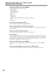
... Remote Commander for this operation (p. 43). Recording data The recording data (date/time or various settings when recorded) are recording a still image You cannot turn off the power or press PHOTO. However, they are recorded automatically onto the "Memory Stick." Fader - Title - This is slightly larger compared with the angle of view in step 2 The image momentarily flickers. To display the recording data, press DATA CODE during playback. You can record on the LCD screen when you press PHOTO lightly in CAMERA mode. Color Slow Shutter...
... Remote Commander for this operation (p. 43). Recording data The recording data (date/time or various settings when recorded) are recording a still image You cannot turn off the power or press PHOTO. However, they are recorded automatically onto the "Memory Stick." Fader - Title - This is slightly larger compared with the angle of view in step 2 The image momentarily flickers. To display the recording data, press DATA CODE during playback. You can record on the LCD screen when you press PHOTO lightly in CAMERA mode. Color Slow Shutter...
Operating Instructions
Page 131
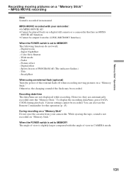
...camcorder. Color Slow Shutter - To display the recording date/time, press DATA CODE during playback. Digital zoom - Fader - SteadyShot When using an external flash (optional) Turn the power of the flash may be played back on "Memory Stick." Otherwise, the charging sound of the external flash off when recording moving pictures on a "Memory Stick" Do not eject the cassette from the i.LINK (MICROMV Interface). However, they are not displayed while recording. During recording on a "Memory Stick" - Digital effect - Super NightShot - Title - Recording date/time The date...
...camcorder. Color Slow Shutter - To display the recording date/time, press DATA CODE during playback. Digital zoom - Fader - SteadyShot When using an external flash (optional) Turn the power of the flash may be played back on "Memory Stick." Otherwise, the charging sound of the external flash off when recording moving pictures on a "Memory Stick" Do not eject the cassette from the i.LINK (MICROMV Interface). However, they are not displayed while recording. During recording on a "Memory Stick" - Digital effect - Super NightShot - Title - Recording date/time The date...
Operating Instructions
Page 134
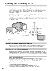
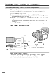
... Before operation Set DISPLAY in to LCD in the menu settings. (The default setting is displayed on to faithfully obtain original pictures. The image of the A/V connecting cable. Using the A/V connecting cable Black Yellow OUT S VIDEO VIDEO AUDIO VCR Red : Signal flow A/V White A/V connecting cable (supplied) If your TV or VCR has an S video jack Connect using the A/V connecting cable, set VIDEOINPUT to the appropriate position depending on the player. (p. 83) (3) Play back the recorded tape on the VCR, or turn the TV on the LCD screen or...
... Before operation Set DISPLAY in to LCD in the menu settings. (The default setting is displayed on to faithfully obtain original pictures. The image of the A/V connecting cable. Using the A/V connecting cable Black Yellow OUT S VIDEO VIDEO AUDIO VCR Red : Signal flow A/V White A/V connecting cable (supplied) If your TV or VCR has an S video jack Connect using the A/V connecting cable, set VIDEOINPUT to the appropriate position depending on the player. (p. 83) (3) Play back the recorded tape on the VCR, or turn the TV on the LCD screen or...

Operating Instructions
Page 156
... with the instructions on page 161. •The title screen is not displayed if the screen size of administrators. Connect the USB cable according to "Making the computer recognize your computer. Carry out installation again in accordance with the steps on the screen. Connecting your camcorder to your computer using the USB cable (For Windows users) Installing the USB driver Start the following operation without connecting the USB cable to your computer is set to...
... with the instructions on page 161. •The title screen is not displayed if the screen size of administrators. Connect the USB cable according to "Making the computer recognize your computer. Carry out installation again in accordance with the steps on the screen. Connecting your camcorder to your computer using the USB cable (For Windows users) Installing the USB driver Start the following operation without connecting the USB cable to your computer is set to...

Operating Instructions
Page 160
... USB cable (For Windows users) Viewing images recorded on a "Memory Stick" (1) Insert a "Memory Stick" into your camcorder before installing the USB driver. 160 Connecting your camcorder to your computer using the supplied USB cable. Your computer recognizes your camcorder. USB MODE appears on the LCD screen of your camcorder, and the Add Hardware Wizard starts. (USB) jack USB connector USB cable (supplied) (4) Follow the on your camcorder to complete without interrupting it. The Add Hardware Wizard starts two times because two different USB drivers...
... USB cable (For Windows users) Viewing images recorded on a "Memory Stick" (1) Insert a "Memory Stick" into your camcorder before installing the USB driver. 160 Connecting your camcorder to your computer using the supplied USB cable. Your computer recognizes your camcorder. USB MODE appears on the LCD screen of your camcorder, and the Add Hardware Wizard starts. (USB) jack USB connector USB cable (supplied) (4) Follow the on your camcorder to complete without interrupting it. The Add Hardware Wizard starts two times because two different USB drivers...

Operating Instructions
Page 161
... the "Device Manager" button. Connecting your camcorder to your computer using the USB cable supplied with your camcorder. 4 Open your computer's "Device Manager". Viewing images recorded on a tape Step 1: Uninstall the incorrect USB driver 1 Turn on your computer and allow Windows to load. 2 Connect the AC power adaptor, and set the POWER switch to VCR. 3 Connect the USB connector on your computer to the (USB) jack on your camcorder using the USB cable (For Windows users) If you cannot install the USB driver The USB driver has been...
... the "Device Manager" button. Connecting your camcorder to your computer using the USB cable supplied with your camcorder. 4 Open your computer's "Device Manager". Viewing images recorded on a tape Step 1: Uninstall the incorrect USB driver 1 Turn on your computer and allow Windows to load. 2 Connect the AC power adaptor, and set the POWER switch to VCR. 3 Connect the USB connector on your computer to the (USB) jack on your camcorder using the USB cable (For Windows users) If you cannot install the USB driver The USB driver has been...

Operating Instructions
Page 163
... your camcorder. 3 Connect the AC power adaptor, and set the POWER switch to MEMORY. 4 Connect the USB connector on your computer to (CHG) OFF on page 156. 163 Select the device prefixed with your camcorder. 5 Open your camcorder using the USB cable supplied with the "?" Ex: (?)Sony Handycam 7 Turn the POWER switch to the (USB) jack on your computer's "Device Manager". Windows 2000 Professional: Select "My Computer" t "Control Panel" t "System" t "Hardware", and click the "Device Manager" button.
... your camcorder. 3 Connect the AC power adaptor, and set the POWER switch to MEMORY. 4 Connect the USB connector on your computer to (CHG) OFF on page 156. 163 Select the device prefixed with your camcorder. 5 Open your camcorder using the USB cable supplied with the "?" Ex: (?)Sony Handycam 7 Turn the POWER switch to the (USB) jack on your computer's "Device Manager". Windows 2000 Professional: Select "My Computer" t "Control Panel" t "System" t "Hardware", and click the "Device Manager" button.

Operating Instructions
Page 164
....1.0 for Sony" You need to install the USB driver and PIXELA ImageMixer to VCR on your camcorder. Viewing images recorded on a tape (1) Turn on your computer and allow Windows to load. (2) Connect the AC power adaptor, and insert a cassette into your camcorder. (3) Set the POWER switch to view images recorded on a tape on your computer - Select USB STREAM in to ON in the menu settings (p. 184). (4) Select "Start" t "Programs" t "PIXELA" t "ImageMixer" t "PIXELA ImageMixer Ver.1.0 for Sony" startup screen appears...
....1.0 for Sony" You need to install the USB driver and PIXELA ImageMixer to VCR on your camcorder. Viewing images recorded on a tape (1) Turn on your computer and allow Windows to load. (2) Connect the AC power adaptor, and insert a cassette into your camcorder. (3) Set the POWER switch to view images recorded on a tape on your computer - Select USB STREAM in to ON in the menu settings (p. 184). (4) Select "Start" t "Programs" t "PIXELA" t "ImageMixer" t "PIXELA ImageMixer Ver.1.0 for Sony" startup screen appears...
Operating Instructions
Page 170
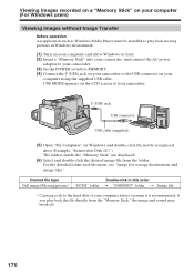
USB MODE appears on the LCD screen of your camcorder. (USB) jack USB connector USB cable (supplied) (5) Open "My Computer" on your camcorder to the hard disk of your computer before viewing it is recommended. If you play back moving pictures in this order Still image/Moving picture* "DCIM" folder t "100MSDCF" folder t Image file * Copying a file to the USB connector on your computer using the supplied USB cable. Viewing images recorded on a "Memory Stick" on your computer (For Windows users) Viewing images without Image Transfer Before operation An application...
USB MODE appears on the LCD screen of your camcorder. (USB) jack USB connector USB cable (supplied) (5) Open "My Computer" on your camcorder to the hard disk of your computer before viewing it is recommended. If you play back moving pictures in this order Still image/Moving picture* "DCIM" folder t "100MSDCF" folder t Image file * Copying a file to the USB connector on your computer using the supplied USB cable. Viewing images recorded on a "Memory Stick" on your computer (For Windows users) Viewing images without Image Transfer Before operation An application...

Operating Instructions
Page 171
... image file Moving picture file Disconnect the USB cable and remove the "Memory Stick" or set the POWER switch to 9999. For Windows 2000 Professional, Windows Me, Windows XP users (1) Move the cursor to the "Unplug or Eject Hardware" icon on your computer (For Windows users) Image file storage destinations and image files Image files recorded with your camcorder are as follows. Viewing images recorded on a "Memory Stick" on the Task Tray and click to cancel the applicable drive. (2) After the "Safe to remove" message...
... image file Moving picture file Disconnect the USB cable and remove the "Memory Stick" or set the POWER switch to 9999. For Windows 2000 Professional, Windows Me, Windows XP users (1) Move the cursor to the "Unplug or Eject Hardware" icon on your computer (For Windows users) Image file storage destinations and image files Image files recorded with your camcorder are as follows. Viewing images recorded on a "Memory Stick" on the Task Tray and click to cancel the applicable drive. (2) After the "Safe to remove" message...

Operating Instructions
Page 174
... USB cable and remove the "Memory Stick" or set the POWER switch to (CHG) OFF. Make sure that the "Memory Stick" access lamp of the screen. (3) Disconnect the USB cable and remove the "Memory Stick" or set the POWER switch to (CHG) OFF. 174 USB MODE appears on the LCD screen of your computer before viewing it , and then select "Eject disk" from the folder. Desired file type Double-click in this order Still image/Moving picture* "DCIM" folder t "100MSDCF" folder t Image file * Copying a file...
... USB cable and remove the "Memory Stick" or set the POWER switch to (CHG) OFF. Make sure that the "Memory Stick" access lamp of the screen. (3) Disconnect the USB cable and remove the "Memory Stick" or set the POWER switch to (CHG) OFF. 174 USB MODE appears on the LCD screen of your computer before viewing it , and then select "Eject disk" from the folder. Desired file type Double-click in this order Still image/Moving picture* "DCIM" folder t "100MSDCF" folder t Image file * Copying a file...

Operating Instructions
Page 178
... use the normal setting. The LCD screen shows only the items you can operate at the moment. P EFFECT -- To adjust the white balance (p. 52) To adjust the sharpness of the image outline with the flash level. 178 Menu items are displayed as the following icons: MANUAL SET CAMERA SET VCR SET LCD/VF SET MEMORY SET CM SET TAPE SET SETUP MENU OTHERS Selecting the mode setting of the POWER switch. RED EYE R z OFF ON FLASH LVL WHT BAL HIGH z NORMAL LOW -- To make the flash level...
... use the normal setting. The LCD screen shows only the items you can operate at the moment. P EFFECT -- To adjust the white balance (p. 52) To adjust the sharpness of the image outline with the flash level. 178 Menu items are displayed as the following icons: MANUAL SET CAMERA SET VCR SET LCD/VF SET MEMORY SET CM SET TAPE SET SETUP MENU OTHERS Selecting the mode setting of the POWER switch. RED EYE R z OFF ON FLASH LVL WHT BAL HIGH z NORMAL LOW -- To make the flash level...

Operating Instructions
Page 185
... screen, LCD screen and viewfinder To light up the camera recording lamp at the front of DST, SUMMERTIME is displayed on the TV or VCR. Other menu items are displayed during playback. DST SET* z OFF ON BEEP z MELODY COMMANDER NORMAL OFF z ON OFF DISPLAY REC LAMP z LCD V-OUT/LCD z ON OFF Meaning POWER switch When you set to their default settings. Changing the menu settings Customizing Your Camcorder Icon/item Mode OTHERS DATA CODE z DATE/CAM (On the Remote Commander) DATE...
... screen, LCD screen and viewfinder To light up the camera recording lamp at the front of DST, SUMMERTIME is displayed on the TV or VCR. Other menu items are displayed during playback. DST SET* z OFF ON BEEP z MELODY COMMANDER NORMAL OFF z ON OFF DISPLAY REC LAMP z LCD V-OUT/LCD z ON OFF Meaning POWER switch When you set to their default settings. Changing the menu settings Customizing Your Camcorder Icon/item Mode OTHERS DATA CODE z DATE/CAM (On the Remote Commander) DATE...
Operating Instructions
Page 186
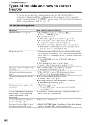
.... Types of trouble and how to expose the red mark. The power goes off to save battery power and to troubleshoot the problem. The SteadyShot function does not work . c Rewind the tape or insert a new one hour to acclimatize (p. 201). • When your camcorder is the manual focus mode. c Remove the cassette and leave your Sony dealer. In the recording mode Symptom START/STOP does not operate. The picture does not appear in the menu settings...
.... Types of trouble and how to expose the red mark. The power goes off to save battery power and to troubleshoot the problem. The SteadyShot function does not work . c Rewind the tape or insert a new one hour to acclimatize (p. 201). • When your camcorder is the manual focus mode. c Remove the cassette and leave your Sony dealer. In the recording mode Symptom START/STOP does not operate. The picture does not appear in the menu settings...
Operating Instructions
Page 193
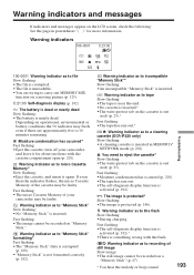
...). •"Memory Stick" is inserted. The image is protected* Slow flashing: •The image is something wrong with the cassette compartment open (p. 201). Fast flashing: •The self-diagnosis display function is activated (p. 192).* •There is protected (p. 146). Warning indicators and messages If indicators and messages appear on the LCD screen, check the following: See the page in MEMORY/ NETWORK mode (p. 202). Depending on operational, environmental or battery conditions...
...). •"Memory Stick" is inserted. The image is protected* Slow flashing: •The image is something wrong with the cassette compartment open (p. 201). Fast flashing: •The self-diagnosis display function is activated (p. 192).* •There is protected (p. 146). Warning indicators and messages If indicators and messages appear on the LCD screen, check the following: See the page in MEMORY/ NETWORK mode (p. 202). Depending on operational, environmental or battery conditions...
Operating Instructions
Page 208
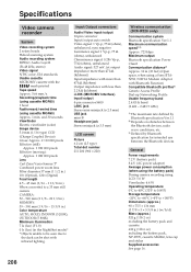
... communication (DCR-IP220 only) Communication system Bluetooth specification Ver.1.1 Maximum communication speed1) 2) Approx. 723 kbps Maximum output Bluetooth specification Power Class2 Communication distance2) Approx. 10 m (33 feet) (Open space, when using a Sony BTANW1/NW1A Modem Adaptor with infrared lighting. Specifications Video camera recorder System Video recording system 2 rotary heads Helical scanning system Audio recording system MPEG1 Audio Layer2 (Fs 48 kHz, stereo) Video signal NTSC color, EIA standards Usable cassette MICROMV cassette with the mark printed Tape speed Approx...
... communication (DCR-IP220 only) Communication system Bluetooth specification Ver.1.1 Maximum communication speed1) 2) Approx. 723 kbps Maximum output Bluetooth specification Power Class2 Communication distance2) Approx. 10 m (33 feet) (Open space, when using a Sony BTANW1/NW1A Modem Adaptor with infrared lighting. Specifications Video camera recorder System Video recording system 2 rotary heads Helical scanning system Audio recording system MPEG1 Audio Layer2 (Fs 48 kHz, stereo) Video signal NTSC color, EIA standards Usable cassette MICROMV cassette with the mark printed Tape speed Approx...

Operating Instructions
Page 219
... Adjusting volume 42 Auto red-eye reduction 49, 116 AUTO SHTR 178 A/V connecting cable 46, 80, 84, 123, 134 BACK LIGHT 37 Battery pack 17 BEEP 185 BOUNCE 56 B&W 58 C, D CALIBRATION 204 Camera chroma key 125 Carl Zeiss lens 214 Cassette information 97 Cassette memory 97 Charging battery 18 Charging built-in rechargeable battery .......... 203 Cleaning cassette 202 Clock set 22 COLOR SLOW SHUTTER .... 38 Continuous photo recording 113 Data code 43 DATE SEARCH 79 DEMO MODE 184 Digital effect 59, 71 DISPLAY...
... Adjusting volume 42 Auto red-eye reduction 49, 116 AUTO SHTR 178 A/V connecting cable 46, 80, 84, 123, 134 BACK LIGHT 37 Battery pack 17 BEEP 185 BOUNCE 56 B&W 58 C, D CALIBRATION 204 Camera chroma key 125 Carl Zeiss lens 214 Cassette information 97 Cassette memory 97 Charging battery 18 Charging built-in rechargeable battery .......... 203 Cleaning cassette 202 Clock set 22 COLOR SLOW SHUTTER .... 38 Continuous photo recording 113 Data code 43 DATE SEARCH 79 DEMO MODE 184 Digital effect 59, 71 DISPLAY...


