Limited Warranty (U.S. Only)
Page 1
...-172-03 General Stereo/Hifi Components/Tape Decks ® CD Players/Mini Disc Players/Audio Systems Hifi Audio LIMITED WARRANTY (U.S. In the event of a defect, these are your rights and obligations with respect to any data, software or other reason, including but while the Parts Warranty below . This Limited Warranty is your responsibility to backup any repair, replacement part or replacement product for...
...-172-03 General Stereo/Hifi Components/Tape Decks ® CD Players/Mini Disc Players/Audio Systems Hifi Audio LIMITED WARRANTY (U.S. In the event of a defect, these are your rights and obligations with respect to any data, software or other reason, including but while the Parts Warranty below . This Limited Warranty is your responsibility to backup any repair, replacement part or replacement product for...
Operating Instructions
Page 1
Home Theatre System 4-435-635-12(1) Operating Instructions US Mode d'emploi FR Manual de instrucciones ES HT-CT60
Home Theatre System 4-435-635-12(1) Operating Instructions US Mode d'emploi FR Manual de instrucciones ES HT-CT60
Operating Instructions
Page 2
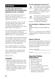
... unit, disconnect the main plug from children. HT-CT60 Serial No. Install in the literature accompanying the appliance. To reduce the risk of fire, do not cover the ventilation opening of the apparatus with the manufacturer's instructions. 2US Should you call upon your Sony dealer regarding this product. Owner's Record The model and serial numbers are located on the apparatus...
... unit, disconnect the main plug from children. HT-CT60 Serial No. Install in the literature accompanying the appliance. To reduce the risk of fire, do not cover the ventilation opening of the apparatus with the manufacturer's instructions. 2US Should you call upon your Sony dealer regarding this product. Owner's Record The model and serial numbers are located on the apparatus...
Operating Instructions
Page 3
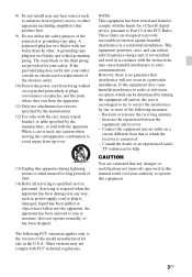
... turning the equipment off and on, the user is used in the U.S.A. Servicing is no guarantee that produce heat. 9) Do not defeat the safety purpose of the following FCC statement applies only to operate this model manufactured for help. These limits are cautioned that to qualified service personnel. Increase the separation between the equipment and receiver. - If the provided plug...
... turning the equipment off and on, the user is used in the U.S.A. Servicing is no guarantee that produce heat. 9) Do not defeat the safety purpose of the following FCC statement applies only to operate this model manufactured for help. These limits are cautioned that to qualified service personnel. Increase the separation between the equipment and receiver. - If the provided plug...
Operating Instructions
Page 4
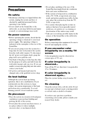
... subject to direct sunlight, excessive dust, or mechanical shock. • Do not place anything at the rear of the surface may result. In this case, place the system away from the TV set , then turn off the TV set . On operation Before connecting other for a long time, be changed only at a large volume, the system temperature of the plug is...
... subject to direct sunlight, excessive dust, or mechanical shock. • Do not place anything at the rear of the surface may result. In this case, place the system away from the TV set , then turn off the TV set . On operation Before connecting other for a long time, be changed only at a large volume, the system temperature of the plug is...
Operating Instructions
Page 5
Dolby and the double-D symbol are trademarks of Dolby Laboratories. 5US Copyrights This model incorporates Dolby* Digital Surround System. * Manufactured under license from Dolby Laboratories.
Dolby and the double-D symbol are trademarks of Dolby Laboratories. 5US Copyrights This model incorporates Dolby* Digital Surround System. * Manufactured under license from Dolby Laboratories.
Operating Instructions
Page 6
Table of contents Precautions 4 Getting Started Unpacking 7 Index to parts and controls 8 Connecting the TV and player, etc 10 Positioning the system 11 Connecting the AC power cord (mains lead 13 Setting up the sound output of the connected equipment .......13 Playback Options Operating the system using the supplied remote control .........14 Controlling a connected TV ........15 Changing the battery 16 Additional Information Troubleshooting 17 Specifications 18 Index 20 6US
Table of contents Precautions 4 Getting Started Unpacking 7 Index to parts and controls 8 Connecting the TV and player, etc 10 Positioning the system 11 Connecting the AC power cord (mains lead 13 Setting up the sound output of the connected equipment .......13 Playback Options Operating the system using the supplied remote control .........14 Controlling a connected TV ........15 Changing the battery 16 Additional Information Troubleshooting 17 Specifications 18 Index 20 6US
Operating Instructions
Page 7
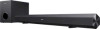
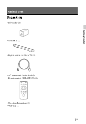
Getting Started Getting Started Unpacking • Subwoofer (1) • Sound Bar (1) • Digital optical cord for a TV (1) • AC power cord (mains lead) (1) • Remote control (RM-ANU159) (1) • Operating Instructions (1) • Warranty (1) 7US
Getting Started Getting Started Unpacking • Subwoofer (1) • Sound Bar (1) • Digital optical cord for a TV (1) • AC power cord (mains lead) (1) • Remote control (RM-ANU159) (1) • Operating Instructions (1) • Warranty (1) 7US
Operating Instructions
Page 8
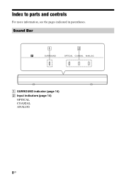
Sound Bar SURROUND OPTICAL COAXIAL ANALOG A SURROUND indicator (page 14) B Input indicators (page 14) OPTICAL COAXIAL ANALOG 8US Index to parts and controls For more information, see the pages indicated in parentheses.
Sound Bar SURROUND OPTICAL COAXIAL ANALOG A SURROUND indicator (page 14) B Input indicators (page 14) OPTICAL COAXIAL ANALOG 8US Index to parts and controls For more information, see the pages indicated in parentheses.
Operating Instructions
Page 9
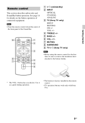
F VOL +*/- A ?/1 (on the button operation of the Sound Bar. VOL +/- Note • Point the remote control toward the center of the front panel of connected equipment. Use it as a guide during operation. • The battery is factory-installed in the remote control. • TV operation buttons work only with Sony TVs. 9US G MUTING H SURROUND I TV ?/1 (Sony TV only) Note • Before using the remote control for details on /standby) B INPUT OPTICAL COAXIAL ANALOG C TV (Sony TV only) INPUT MUTING CH...
F VOL +*/- A ?/1 (on the button operation of the Sound Bar. VOL +/- Note • Point the remote control toward the center of the front panel of connected equipment. Use it as a guide during operation. • The battery is factory-installed in the remote control. • TV operation buttons work only with Sony TVs. 9US G MUTING H SURROUND I TV ?/1 (Sony TV only) Note • Before using the remote control for details on /standby) B INPUT OPTICAL COAXIAL ANALOG C TV (Sony TV only) INPUT MUTING CH...
Operating Instructions
Page 10
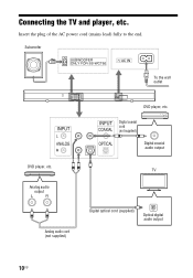
Subwoofer To the wall outlet DVD player, etc. Connecting the TV and player, etc. Insert the plug of the AC power cord (mains lead) fully to the end. Analog audio output Analog audio cord (not supplied) DVD player, etc. Digital coaxial cord (not supplied) Digital coaxial audio output TV Digital optical cord (supplied) Optical digital audio output 10US
Subwoofer To the wall outlet DVD player, etc. Connecting the TV and player, etc. Insert the plug of the AC power cord (mains lead) fully to the end. Analog audio output Analog audio cord (not supplied) DVD player, etc. Digital coaxial cord (not supplied) Digital coaxial audio output TV Digital optical cord (supplied) Optical digital audio output 10US
Operating Instructions
Page 11
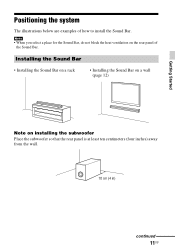
Installing the Sound Bar • Installing the Sound Bar on a rack • Installing the Sound Bar on a wall (page 12) Getting Started Note on the rear panel of how to install the Sound Bar. Note • When you select a place for the Sound Bar, do not block the heat ventilation on installing the subwoofer Place the subwoofer so that the rear panel is at least ten centimeters (four inches) away from the wall. 10 cm (4 in) continued 11US Positioning the system The illustrations below are examples of the Sound Bar.
Installing the Sound Bar • Installing the Sound Bar on a rack • Installing the Sound Bar on a wall (page 12) Getting Started Note on the rear panel of how to install the Sound Bar. Note • When you select a place for the Sound Bar, do not block the heat ventilation on installing the subwoofer Place the subwoofer so that the rear panel is at least ten centimeters (four inches) away from the wall. 10 cm (4 in) continued 11US Positioning the system The illustrations below are examples of the Sound Bar.
Operating Instructions
Page 12
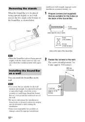
... special attention to safety during the installation. • Sony is to be placed facing upward slightly or on the back of the Sound Bar Note • When the Sound Bar is especially fragile, attach the screws securely to block the ventilation holes with the stands removed, take care not to a wall beam. The screws should protrude...
... special attention to safety during the installation. • Sony is to be placed facing upward slightly or on the back of the Sound Bar Note • When the Sound Bar is especially fragile, attach the screws securely to block the ventilation holes with the stands removed, take care not to a wall beam. The screws should protrude...
Operating Instructions
Page 13
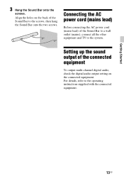
... holes on the back of the connected equipment To output multi-channel digital audio, check the digital audio output setting on the connected equipment. For details, refer to the system. Connecting the AC power cord (mains lead) Before connecting the AC power cord (mains lead) of the Sound Bar to a wall outlet (mains), connect all the other equipment and TV to the operating instructions supplied with the connected equipment. 13US Getting Started 3 Hang...
... holes on the back of the connected equipment To output multi-channel digital audio, check the digital audio output setting on the connected equipment. For details, refer to the system. Connecting the AC power cord (mains lead) Before connecting the AC power cord (mains lead) of the Sound Bar to a wall outlet (mains), connect all the other equipment and TV to the operating instructions supplied with the connected equipment. 13US Getting Started 3 Hang...
Operating Instructions
Page 14
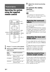
... Operating the system using the supplied remote control 3 Adjust the volume by pressing VOL +/-. To activate the muting function Press MUTING. Tip • The sound may be output from the TV's speaker. VOL +/- 1 Press ?/1 to the ANALOG jacks Enjoying the surround effect This system can create multichannel surround sound. When bass or treble is available only for Dolby encoded TV programs, DVD, and Blu-ray discsTM. 14US Enjoying sound at low volume (night mode...
... Operating the system using the supplied remote control 3 Adjust the volume by pressing VOL +/-. To activate the muting function Press MUTING. Tip • The sound may be output from the TV's speaker. VOL +/- 1 Press ?/1 to the ANALOG jacks Enjoying the surround effect This system can create multichannel surround sound. When bass or treble is available only for Dolby encoded TV programs, DVD, and Blu-ray discsTM. 14US Enjoying sound at low volume (night mode...
Operating Instructions
Page 15
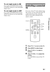
... +/- to adjust the volume. INPUT Playback Options 1 Press TV ?/1 to turn off the TV sound. 15US to select a channel. 4 Press TV VOL +/- Controlling a connected TV If you use a Sony TV only without using this system, you can control the Sony TV connected to the system, using the buttons with yellow printing on the remote control. Press MUTING to turn on the TV. 2 Press INPUT to select input. 3 Press TV CH +/- To set night mode to...
... +/- to adjust the volume. INPUT Playback Options 1 Press TV ?/1 to turn off the TV sound. 15US to select a channel. 4 Press TV VOL +/- Controlling a connected TV If you use a Sony TV only without using this system, you can control the Sony TV connected to the system, using the buttons with yellow printing on the remote control. Press MUTING to turn on the TV. 2 Press INPUT to select input. 3 Press TV CH +/- To set night mode to...
Operating Instructions
Page 16
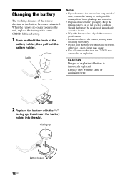
...; If you do not use the remote for a long period of time, remove the battery to observe the correct polarity when installing the battery. • Do not hold the latch of batteries other than the CR2025 may cause a fire or explosion. Changing the battery The working distance of explosion if battery is incorrectly replaced. Should the battery...
...; If you do not use the remote for a long period of time, remove the battery to observe the correct polarity when installing the battery. • Do not hold the latch of batteries other than the CR2025 may cause a fire or explosion. Changing the battery The working distance of explosion if battery is incorrectly replaced. Should the battery...
Operating Instructions
Page 17
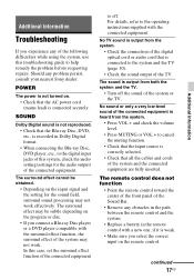
... depending on the program or disc. • If you connect a Blu-ray Disc player or a DVD player compatible with a new one, if it is correctly selected. • Check that all the cables and cords of the connected equipment. In this case, set the surround effect function of the connected equipment to the digital input jacks of this troubleshooting guide to cancel the muting function. • Check that the input source is weak. • Make sure you experience...
... depending on the program or disc. • If you connect a Blu-ray Disc player or a DVD player compatible with a new one, if it is correctly selected. • Check that all the cables and cords of the connected equipment. In this case, set the surround effect function of the connected equipment to the digital input jacks of this troubleshooting guide to cancel the muting function. • Check that the input source is weak. • Make sure you experience...
Operating Instructions
Page 18
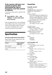
...; 2 7/8 in × 2 3/4 in) (without stands) 18US Format Supported/Not supported Dolby Digital a Linear PCM 2ch 48 kHz a or less Sound Bar Amplifier section U.S. models: POWER OUTPUT AND TOTAL HARMONIC DISTORTION: (FTC) Front L + Front R: With 4 ohms loads, both channels driven, from 250 milliwatts to rated output. After checking the above item and fixing any problems, turn on the remote control for the operation. 1 Press BASS +, VOL -, and TREBLE + in ) (with no...
...; 2 7/8 in × 2 3/4 in) (without stands) 18US Format Supported/Not supported Dolby Digital a Linear PCM 2ch 48 kHz a or less Sound Bar Amplifier section U.S. models: POWER OUTPUT AND TOTAL HARMONIC DISTORTION: (FTC) Front L + Front R: With 4 ohms loads, both channels driven, from 250 milliwatts to rated output. After checking the above item and fixing any problems, turn on the remote control for the operation. 1 Press BASS +, VOL -, and TREBLE + in ) (with no...
Operating Instructions
Page 19
Additional Information Mass (approx.) 1.6 kg (3 lb 8 3/8 oz) Subwoofer POWER OUTPUT (reference) 30 W (per channel at 8 ohms, 100 Hz) Speaker system Subwoofer, Bass reflex Speaker unit 130 mm (5 1/8 in) cone type Rated impedance 8 ohms Dimensions (approx.) 170 mm × 245 mm × 300 mm (6 3/4 in × 9 3/4 in × 11 7/8 in) (w/h/d) Mass (approx.) 2.7 kg (5 lb 15 1/4 oz) Design and specifications are subject to change without notice. 19US
Additional Information Mass (approx.) 1.6 kg (3 lb 8 3/8 oz) Subwoofer POWER OUTPUT (reference) 30 W (per channel at 8 ohms, 100 Hz) Speaker system Subwoofer, Bass reflex Speaker unit 130 mm (5 1/8 in) cone type Rated impedance 8 ohms Dimensions (approx.) 170 mm × 245 mm × 300 mm (6 3/4 in × 9 3/4 in × 11 7/8 in) (w/h/d) Mass (approx.) 2.7 kg (5 lb 15 1/4 oz) Design and specifications are subject to change without notice. 19US


