Operation Manual
Page 2
...or electrical shock, refer servicing to the presence of a different line cord or attachment plug, or both. Refer servicing to operate this manual could void your authority to qualified personnel only. Ne confier l'entretien de l'appareil qu'à un personnel qualifié. The shielded ..., uses, and can radiate radio frequency energy and, if not installed and used in ) Rating Minimum 10 A, 125 V Using this manual must be required to radio communications. To avoid electrical shock, do not expose the unit to provide reasonable protection against harmful interference when the...
...or electrical shock, refer servicing to the presence of a different line cord or attachment plug, or both. Refer servicing to operate this manual could void your authority to qualified personnel only. Ne confier l'entretien de l'appareil qu'à un personnel qualifié. The shielded ..., uses, and can radiate radio frequency energy and, if not installed and used in ) Rating Minimum 10 A, 125 V Using this manual must be required to radio communications. To avoid electrical shock, do not expose the unit to provide reasonable protection against harmful interference when the...
Operation Manual
Page 5
... 5-11 5-2-1 Overview of DMC Editing 5-11 5-2-2 Carrying Out DMC Editing 5-12 5-3 Special Automatic Editing Methods 5-13 5-3-1 Quick Editing 5-13 5-3-2 Continuous Editing 5-13 5-3-3 Standalone Editing 5-14 5-3-4 Manual Editing 5-14 5-3-5 Preread Editing 5-14 1 Table of Contents
... 5-11 5-2-1 Overview of DMC Editing 5-11 5-2-2 Carrying Out DMC Editing 5-12 5-3 Special Automatic Editing Methods 5-13 5-3-1 Quick Editing 5-13 5-3-2 Continuous Editing 5-13 5-3-3 Standalone Editing 5-14 5-3-4 Manual Editing 5-14 5-3-5 Preread Editing 5-14 1 Table of Contents
Operation Manual
Page 9
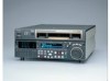
... of VTRs simultaneously. Rack mounting Using the optional RMM-131 Rack Mount Adaptor, you can also control a number of rack mounting, refer to the Installation Manual. 1-3 Chapter 1 Overview Since two remote control connectors are provided, you can be controlled from an external remote controller or editor through the parallel interface. Additionally...
... of VTRs simultaneously. Rack mounting Using the optional RMM-131 Rack Mount Adaptor, you can also control a number of rack mounting, refer to the Installation Manual. 1-3 Chapter 1 Overview Since two remote control connectors are provided, you can be controlled from an external remote controller or editor through the parallel interface. Additionally...
Operation Manual
Page 12
... cassette. When using the lower control panel as remote control panel, press the DELETE button and STOP button at the same time to the Installation Manual.
... cassette. When using the lower control panel as remote control panel, press the DELETE button and STOP button at the same time to the Installation Manual.
Operation Manual
Page 20
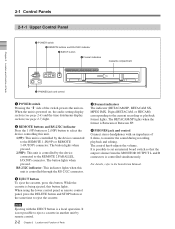
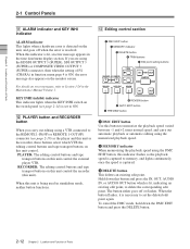
... while pressing this button together with the PLAY button, turning it on. In this case the button does not light. 3 EDIT button To carry out manual editing, press this indicator is on, recording on the tape. To return to monitor the input signal selected with the ASSEMBLE button or INSERT buttons...
... while pressing this button together with the PLAY button, turning it on. In this case the button does not light. 3 EDIT button To carry out manual editing, press this indicator is on, recording on the tape. To return to monitor the input signal selected with the ASSEMBLE button or INSERT buttons...
Operation Manual
Page 22
... 2-14) is captured. 3 DELETE button This deletes an existing edit point. When the button flashes, it is lit, an error message appears in the Maintenance Manual Volume 1. For details on error messages, refer to ON. When this unit control. When this unit is being used in function menu page 4 is ON...
... 2-14) is captured. 3 DELETE button This deletes an existing edit point. When the button flashes, it is lit, an error message appears in the Maintenance Manual Volume 1. For details on error messages, refer to ON. When this unit control. When this unit is being used in function menu page 4 is ON...
Operation Manual
Page 24
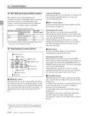
... similar control panel to update this unit. Note After inserting a memory stick or memory card, allow at least five seconds to the Maintenance Manual Volume 1. 2-14 Chapter 2 Location and Function of Parts 2-1 Control Panels 2-1-3 Switch Panel To access the switch panel, open the lower control.... FRONT: Enables the control panel connected to the CONTROL PANEL connector on firmware update and setup menu reading/ storing, refer to the Maintenance Manual Volume 1. 2 Memory card ejection button Press to eject a memory card from the memory card slot. 3 CONTROL PANEL connector (10-pin,...
... similar control panel to update this unit. Note After inserting a memory stick or memory card, allow at least five seconds to the Maintenance Manual Volume 1. 2-14 Chapter 2 Location and Function of Parts 2-1 Control Panels 2-1-3 Switch Panel To access the switch panel, open the lower control.... FRONT: Enables the control panel connected to the CONTROL PANEL connector on firmware update and setup menu reading/ storing, refer to the Maintenance Manual Volume 1. 2 Memory card ejection button Press to eject a memory card from the memory card slot. 3 CONTROL PANEL connector (10-pin,...
Operation Manual
Page 28
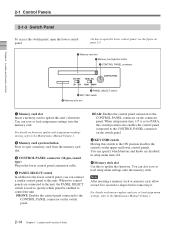
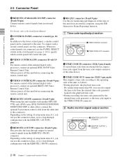
For details, refer to the Installation Manual. 2 CONTROL PANEL connector (round type, 10pin) In addition to the lower control panel, a similar control panel can use the PANEL SELECT switch on the setting ...
For details, refer to the Installation Manual. 2 CONTROL PANEL connector (round type, 10pin) In addition to the lower control panel, a similar control panel can use the PANEL SELECT switch on the setting ...
Operation Manual
Page 38
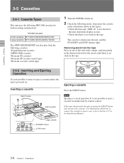
... the tape slacks inside the unit, pressing the EJECT button may not eject the cassette. It is not possible to Section 1-17 in the Installation Manual. STANDBY REW PLAY F FWD STOP Large cassette STANDBY button STOP button 3-8 Chapter 3 Preparations Inserting a cassette EJECT button 1 2 Small cassette Ejecting a cassette Press the EJECT button...
... the tape slacks inside the unit, pressing the EJECT button may not eject the cassette. It is not possible to Section 1-17 in the Installation Manual. STANDBY REW PLAY F FWD STOP Large cassette STANDBY button STOP button 3-8 Chapter 3 Preparations Inserting a cassette EJECT button 1 2 Small cassette Ejecting a cassette Press the EJECT button...
Operation Manual
Page 40
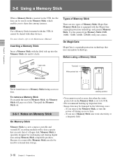
... near static electricity or a magnetic field 3-10 Chapter 3 Preparations If you remove the Memory Stick, or turn the power off during access to the Maintenance Manual. For more details, refer to data. Types of Memory Stick There are two types of a floppy disk. Use the general type Memory Stick (8MB, 16MB...
... near static electricity or a magnetic field 3-10 Chapter 3 Preparations If you remove the Memory Stick, or turn the power off during access to the Maintenance Manual. For more details, refer to data. Types of Memory Stick There are two types of a floppy disk. Use the general type Memory Stick (8MB, 16MB...
Operation Manual
Page 41
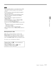
...Manual. Do not turn off the power of the camera or remove the Memory Stick. This may damage the data. For details, refer to corrosive gases • When you carry or store a Memory Stick, keep a Memory Stick in locations that are: - Memory Stick and are the trademarks of Sony...labeling position. Under direct sunlight - Extremely hot such as in a car parked in its case. MagicGate Memory Stick and are the trademarks of Sony Corporation. Chapter 3 Preparations Notes • Prevent metallic objects or your finger from or written to the Memory Stick, do not shake the ...
...Manual. Do not turn off the power of the camera or remove the Memory Stick. This may damage the data. For details, refer to corrosive gases • When you carry or store a Memory Stick, keep a Memory Stick in locations that are: - Memory Stick and are the trademarks of Sony...labeling position. Under direct sunlight - Extremely hot such as in a car parked in its case. MagicGate Memory Stick and are the trademarks of Sony Corporation. Chapter 3 Preparations Notes • Prevent metallic objects or your finger from or written to the Memory Stick, do not shake the ...
Operation Manual
Page 44
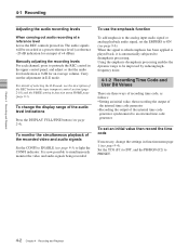
...(F2) to deemphasis processing. 4-1 Recording Adjusting the audio recording levels When carrying out audio recording at a preset reference level (a reference -20 dB indication for an average volume. The audio signals will be improved by reducing highfrequency noise. 4-1-2 Recording Time Code and User Bit Values... button in the tape transport control section (page 2-10) and the PB/EE setting in function menu page 1 (see page 2-4). Manually adjusting the recording levels For each channel, press to ON (see page 9-3) to simultaneously monitor the video and audio signals being recorded....
...(F2) to deemphasis processing. 4-1 Recording Adjusting the audio recording levels When carrying out audio recording at a preset reference level (a reference -20 dB indication for an average volume. The audio signals will be improved by reducing highfrequency noise. 4-1-2 Recording Time Code and User Bit Values... button in the tape transport control section (page 2-10) and the PB/EE setting in function menu page 1 (see page 2-4). Manually adjusting the recording levels For each channel, press to ON (see page 9-3) to simultaneously monitor the video and audio signals being recorded....
Operation Manual
Page 58
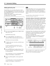
... possible when the recording mode is impossible. However, as soon as you set the required edit points. Once an edit point is set manually or automatically. Audio IN point Recorder IN point Audio OUT point OUT point Player Audio IN point IN point Audio OUT point OUT point ...in jog or shuttle mode. For details, refer to CH4, CUE, or TC). Z 4 1 23 1 Press the desired INSERT button (VIDEO, CH1 to the Installation Manual. 5-4 Chapter 5 Editing The IN/OUT buttons flash. 2 Press the RECORDER or PLAYER button to select the VTR for the recorder and player, the DELETE button...
... possible when the recording mode is impossible. However, as soon as you set the required edit points. Once an edit point is set manually or automatically. Audio IN point Recorder IN point Audio OUT point OUT point Player Audio IN point IN point Audio OUT point OUT point ...in jog or shuttle mode. For details, refer to CH4, CUE, or TC). Z 4 1 23 1 Press the desired INSERT button (VIDEO, CH1 to the Installation Manual. 5-4 Chapter 5 Editing The IN/OUT buttons flash. 2 Press the RECORDER or PLAYER button to select the VTR for the recorder and player, the DELETE button...
Operation Manual
Page 67
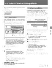
... out continuous editing. 5-3 Special Automatic Editing Methods This section describes the following automatic editing methods: • Quick editing • Continuous editing • Standalone editing • Manual editing • Preread editing 5-3-1 Quick Editing After selecting the edit mode, you can save on the monitor, at the position you wish to make the...
... out continuous editing. 5-3 Special Automatic Editing Methods This section describes the following automatic editing methods: • Quick editing • Continuous editing • Standalone editing • Manual editing • Preread editing 5-3-1 Quick Editing After selecting the edit mode, you can save on the monitor, at the position you wish to make the...
Operation Manual
Page 68
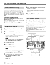
... ends, and the recorder continues with neither the PLAYER button or RECORDER button lit. For preread editing, set the OUT point. 5-3-4 Manual Editing Use the following procedure to carry out manual editing. 1 Press the RECORDER button, turning it is now possible to carry out automatic editing. Note It takes about two seconds...
... ends, and the recorder continues with neither the PLAYER button or RECORDER button lit. For preread editing, set the OUT point. 5-3-4 Manual Editing Use the following procedure to carry out manual editing. 1 Press the RECORDER button, turning it is now possible to carry out automatic editing. Note It takes about two seconds...
Operation Manual
Page 71
... shooting), you can therefore sort the read in time code order. 6-1 Chapter 6 Shot Mark Function Written by cassette in by this unit Possible Written by a manual shot mark operation during recording (crash recording or assemble editing). When the tape includes shot data (camera, time, and other information captured at the time...
... shooting), you can therefore sort the read in time code order. 6-1 Chapter 6 Shot Mark Function Written by cassette in by this unit Possible Written by a manual shot mark operation during recording (crash recording or assemble editing). When the tape includes shot data (camera, time, and other information captured at the time...
Operation Manual
Page 93
... changes and exit the setup menu Press the F6 (EXIT) button. 2 Press the F5 (SET) button. This makes the setting effective. Refer to the Maintenance Manual Volume 1 for more information about the error logger. Time zone settings The UMID uses the UTC (Coordinated Universal Time) time standard. Select any character to...
... changes and exit the setup menu Press the F6 (EXIT) button. 2 Press the F5 (SET) button. This makes the setting effective. Refer to the Maintenance Manual Volume 1 for more information about the error logger. Time zone settings The UMID uses the UTC (Coordinated Universal Time) time standard. Select any character to...
Operation Manual
Page 97
...display the HOME2 page by factory default: the HOME page and six pages numbered 1 to the Maintenance Manual Volume 1. IN PB/EE CONFI CTL/TC MENU TCGSET SDI EE DISABL TC HOME F1 F2 F3 ...IN) in the HOME2 page). It is shipped from the function menu items in that page. This manual refers to F6 buttons in function menu HOME page is "panel". You can be assigned to the ...page 6 when the unit is not possible to display the HOME2 page unless you to the Maintenance Manual Volume 1. You can define up of seven pages by setting user-defined function keys. For details ...
...display the HOME2 page by factory default: the HOME page and six pages numbered 1 to the Maintenance Manual Volume 1. IN PB/EE CONFI CTL/TC MENU TCGSET SDI EE DISABL TC HOME F1 F2 F3 ...IN) in the HOME2 page). It is shipped from the function menu items in that page. This manual refers to F6 buttons in function menu HOME page is "panel". You can be assigned to the ...page 6 when the unit is not possible to display the HOME2 page unless you to the Maintenance Manual Volume 1. You can define up of seven pages by setting user-defined function keys. For details ...
Operation Manual
Page 101
...page. Note When controlling the unit from the HKDV-503/900, set to adjust 23.98PsF, 24PsF the value across the range ±30°. Manual setting: With the displayed setting flashing, you can rotate the MULTI CONTROL knob to the standard level. F3 (CHROMA) Sets the HD/SD chroma ...: With the displayed setting flashing, you can rotate the MULTI CONTROL knob to adjust the black level across the range ±100 ns. Manual setting: With the displayed setting flashing, you can rotate the MULTI CONTROL knob to adjust 23.98PsF, 24PsF the setup level across the range &#...
...page. Note When controlling the unit from the HKDV-503/900, set to adjust 23.98PsF, 24PsF the value across the range ±30°. Manual setting: With the displayed setting flashing, you can rotate the MULTI CONTROL knob to the standard level. F3 (CHROMA) Sets the HD/SD chroma ...: With the displayed setting flashing, you can rotate the MULTI CONTROL knob to adjust the black level across the range ±100 ns. Manual setting: With the displayed setting flashing, you can rotate the MULTI CONTROL knob to adjust 23.98PsF, 24PsF the setup level across the range &#...
Operation Manual
Page 105
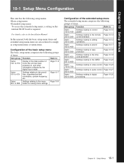
... by the digital hours meter Page 11-5 Items 001 to 019 Settings relating to the preroll time, superimposed text information, system frequency, etc. In this manual, both the basic setup menu items and extended setup menu items are also referred to simply as setup menu items or menu items. Configuration of...-23 700 to 799 Items Settings relating to audio control Page 10-27 800 to 899 Items Settings relating to digital 900 to the Installation Manual.
... by the digital hours meter Page 11-5 Items 001 to 019 Settings relating to the preroll time, superimposed text information, system frequency, etc. In this manual, both the basic setup menu items and extended setup menu items are also referred to simply as setup menu items or menu items. Configuration of...-23 700 to 799 Items Settings relating to audio control Page 10-27 800 to 899 Items Settings relating to digital 900 to the Installation Manual.


