Operating Guide
Page 5
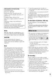
... the hard disk from being broken or recorded images from the camcorder. - to apply mechanical shock or vibration to the camcorder. • When connecting your authority to operate this equipment does cause harmful interference to provide reasonable protection against harmful interference in a particular installation. Declaration of California, USA only Perchlorate Material - Notes HDR-SR5, HDR-SR7 and HDR...
... the hard disk from being broken or recorded images from the camcorder. - to apply mechanical shock or vibration to the camcorder. • When connecting your authority to operate this equipment does cause harmful interference to provide reasonable protection against harmful interference in a particular installation. Declaration of California, USA only Perchlorate Material - Notes HDR-SR5, HDR-SR7 and HDR...
Operating Guide
Page 8
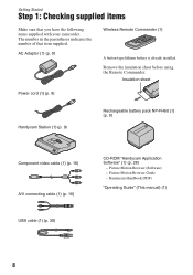
Insulation sheet Power cord (1) (p. 9) Handycam Station (1) (p. 9) Rechargeable battery pack NP-FH60 (1) (p. 9) Component video cable (1) (p. 16) A/V connecting cable (1) (p. 16) USB cable (1) (p. 30) CD-ROM "Handycam Application Software" (1) (p. 26) - Handycam Handbook (PDF) "Operating Guide" (This manual) (1) 8 Getting Started Step 1: Checking supplied items Make sure that item supplied. AC Adaptor... in the parentheses indicates the number of that you have the following items supplied with your camcorder. Remove the insulation sheet before using the Remote Commander.
Insulation sheet Power cord (1) (p. 9) Handycam Station (1) (p. 9) Rechargeable battery pack NP-FH60 (1) (p. 9) Component video cable (1) (p. 16) A/V connecting cable (1) (p. 16) USB cable (1) (p. 30) CD-ROM "Handycam Application Software" (1) (p. 26) - Handycam Handbook (PDF) "Operating Guide" (This manual) (1) 8 Getting Started Step 1: Checking supplied items Make sure that item supplied. AC Adaptor... in the parentheses indicates the number of that you have the following items supplied with your camcorder. Remove the insulation sheet before using the Remote Commander.
Operating Guide
Page 9
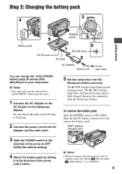
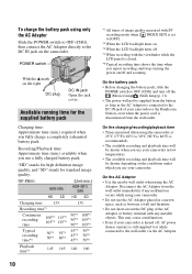
...) lamp lights up . 2 Connect the power cord to the DC IN jack on the DC plug is fully charged. Remove the camcorder from the Handycam Station. b Notes • Your camcorder operates only with an "InfoLITHIUM" battery pack (H series). 1 Connect the AC Adaptor to the AC Adaptor and the wall outlet.... 5 Set the camcorder onto the Handycam Station securely. BATT (battery release) lever 3 Slide the POWER switch in the direction of the arrow to OFF (CHG) (the default setting)....
...) lamp lights up . 2 Connect the power cord to the DC IN jack on the DC plug is fully charged. Remove the camcorder from the Handycam Station. b Notes • Your camcorder operates only with an "InfoLITHIUM" battery pack (H series). 1 Connect the AC Adaptor to the AC Adaptor and the wall outlet.... 5 Set the camcorder onto the Handycam Station securely. BATT (battery release) lever 3 Slide the POWER switch in the direction of the arrow to OFF (CHG) (the default setting)....
Operating Guide
Page 10
... AC Adaptor. NP-FH60: HDR-SR5 HD SD (Unit:min.) HDR-SR7/ SR8 HD SD Charging... time 135 Recording time*1 Continuous recording time 100*2 115*2 105*3 125*3 Typical recording time*5 50*2 55*2 50*3 60*3 135 90*2 100*2 90*3 105*3 90*4 105*4 45*2 50*2 45*3 50*3 45*4 50*4 Playback time*2 145 165 140 160 10 *1 All times of your camcorder or the Handycam Station...high definition image quality, and "SD" stands for the supplied battery pack Charging time: Approximate time (min.) required when you repeat recording start/stop, turning the power on the camcorder...
... AC Adaptor. NP-FH60: HDR-SR5 HD SD (Unit:min.) HDR-SR7/ SR8 HD SD Charging... time 135 Recording time*1 Continuous recording time 100*2 115*2 105*3 125*3 Typical recording time*5 50*2 55*2 50*3 60*3 135 90*2 100*2 90*3 105*3 90*4 105*4 45*2 50*2 45*3 50*3 45*4 50*4 Playback time*2 145 165 140 160 10 *1 All times of your camcorder or the Handycam Station...high definition image quality, and "SD" stands for the supplied battery pack Charging time: Approximate time (min.) required when you repeat recording start/stop, turning the power on the camcorder...
Operating Guide
Page 16
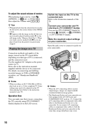
... Connection methods and quality of the TV. Refer also to the instruction manuals supplied with SD (standard definition) image quality. • The Handycam Station and your camcorder are connecting the TV correctly using [TV CONNECT Guide] displayed on connecting and dubbing recorded images to ... tab that you are both the Handycam Station and your camcorder and TV referring to the connected jack. r Connect your camcorder at the same time, image disturbance may need to jacks on your camcorder. r Make the required output settings on your camcorder. b Notes • When the...
... Connection methods and quality of the TV. Refer also to the instruction manuals supplied with SD (standard definition) image quality. • The Handycam Station and your camcorder are connecting the TV correctly using [TV CONNECT Guide] displayed on connecting and dubbing recorded images to ... tab that you are both the Handycam Station and your camcorder and TV referring to the connected jack. r Connect your camcorder at the same time, image disturbance may need to jacks on your camcorder. r Make the required output settings on your camcorder. b Notes • When the...

Operating Guide
Page 17
Move the power zoom lever slightly for a faster zoom. Move it further for a slower zoom. You can magnify still images from about 1.1 to 5 times the original size (Playback zoom). • When you touch the screen during playback zoom, the point you touched will be displayed in ( ) are reference pages. Parts and functions used for the camcorder The numbers in the center of the displayed frame. 2 PHOTO button (13) 3 Eyecup (HDR-SR7/SR8) 4 Viewfinder (12) (HDR-SR7/SR8) 17 Recording/Playback Handycam Station 1 Power zoom lever To use the zoom, move the power zoom lever.
Move the power zoom lever slightly for a faster zoom. Move it further for a slower zoom. You can magnify still images from about 1.1 to 5 times the original size (Playback zoom). • When you touch the screen during playback zoom, the point you touched will be displayed in ( ) are reference pages. Parts and functions used for the camcorder The numbers in the center of the displayed frame. 2 PHOTO button (13) 3 Eyecup (HDR-SR7/SR8) 4 Viewfinder (12) (HDR-SR7/SR8) 17 Recording/Playback Handycam Station 1 Power zoom lever To use the zoom, move the power zoom lever.
Operating Guide
Page 27
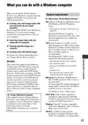
...Hard disk: Disk volume required for details. Attention This camcorder captures high definition footage in a multi-boot environment. One Touch Disc Burn - However, DVD media containing AVCHD...High Color (16 bit color) Others: USB port (this must be copied onto DVD media. Creating an AVCHD format disc/DVDvideo - Operation is not supported by one simple operation By pressing DISC BURN on the Handycam Station (p. 19), you can save images recorded on your camcorder... above OS has been upgraded or in the AVCHD format. http://guide.d-imaging.sony.co.jp/mac/ ms/us/ System requirements...
...Hard disk: Disk volume required for details. Attention This camcorder captures high definition footage in a multi-boot environment. One Touch Disc Burn - However, DVD media containing AVCHD...High Color (16 bit color) Others: USB port (this must be copied onto DVD media. Creating an AVCHD format disc/DVDvideo - Operation is not supported by one simple operation By pressing DISC BURN on the Handycam Station (p. 19), you can save images recorded on your camcorder... above OS has been upgraded or in the AVCHD format. http://guide.d-imaging.sony.co.jp/mac/ ms/us/ System requirements...
Operating Guide
Page 28
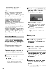
...the power source when you agree, then click [Next]. 8 Connect your camcorder to the computer following the steps below. 1 Connect the AC Adaptor to the Handycam Station and a wall outlet. If the screen does not appear 1 Click [Start...], then click [My Computer]. (For Windows 2000, double-click [My Computer].) 2 Double-click [SONYPICTUTIL (E:)] (CD-ROM) (disc drive).* * Drive names (such as an Administrator for installation. • Close all applications running may be dropped from movies with HD (high definition...
...the power source when you agree, then click [Next]. 8 Connect your camcorder to the computer following the steps below. 1 Connect the AC Adaptor to the Handycam Station and a wall outlet. If the screen does not appear 1 Click [Start...], then click [My Computer]. (For Windows 2000, double-click [My Computer].) 2 Double-click [SONYPICTUTIL (E:)] (CD-ROM) (disc drive).* * Drive names (such as an Administrator for installation. • Close all applications running may be dropped from movies with HD (high definition...

Operating Guide
Page 29
... AVCHD format disc - One of your computer. 29 Windows Media Format 9 Series Runtime (Windows 2000 only) Software required to install the software. The installation is complete. 12Remove the CD-ROM from the disc drive of the following installation screens appears, depending on the computer environment. Enjoying with a computer 2 Set the camcorder onto the Handycam Station...
... AVCHD format disc - One of your computer. 29 Windows Media Format 9 Series Runtime (Windows 2000 only) Software required to install the software. The installation is complete. 12Remove the CD-ROM from the disc drive of the following installation screens appears, depending on the computer environment. Enjoying with a computer 2 Set the camcorder onto the Handycam Station...

Operating Guide
Page 30
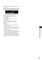
... The [USB SELECT] screen appears on the LCD screen of your camcorder to the computer by the following steps. 1 Connect the AC Adaptor to the Handycam Station and a wall outlet. 2 Set the camcorder onto the Handycam Station, then slide the POWER switch to turn on the desktop. Touch .... • Connect the USB ports of the Handycam Station and a computer using the USB cable. Recommended USB cable connection To assure the proper functioning of your camcorder, connect your camcorder to a computer as standard equipment, connect the Handycam Station to another USB port using the USB cable. ...
... The [USB SELECT] screen appears on the LCD screen of your camcorder to the computer by the following steps. 1 Connect the AC Adaptor to the Handycam Station and a wall outlet. 2 Set the camcorder onto the Handycam Station, then slide the POWER switch to turn on the desktop. Touch .... • Connect the USB ports of the Handycam Station and a computer using the USB cable. Recommended USB cable connection To assure the proper functioning of your camcorder, connect your camcorder to a computer as standard equipment, connect the Handycam Station to another USB port using the USB cable. ...
Operating Guide
Page 31
...). 4 Touch [END] on the screen of your camcorder. 5 Touch [YES] on the hard disk of your camcorder. 6 Disconnect the USB cable from the Handycam Station and the computer. Otherwise, files stored on the screen of your camcorder or in a "Memory Stick Duo" may cause a malfunction of the hard disk of your camcorder, disconnect the USB cable following the proper procedures...
...). 4 Touch [END] on the screen of your camcorder. 5 Touch [YES] on the hard disk of your camcorder. 6 Disconnect the USB cable from the Handycam Station and the computer. Otherwise, files stored on the screen of your camcorder or in a "Memory Stick Duo" may cause a malfunction of the hard disk of your camcorder, disconnect the USB cable following the proper procedures...
Operating Guide
Page 32
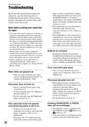
... sending your camcorder for any problems using a pointed object. (If you press the RESET button, all settings, including the clock setting, are reset.) • The temperature of your camcorder is extremely high. The power does not turn on . Your camcorder gets warm....the camcorder onto the Handycam Station securely (p. 9). If the functions still do not work , press the RESET button (p. 19) using your Sony dealer. For details on the problem. We will be required to initialize or change the current hard disk of the camcorder, depending on Easy Handycam operation...
... sending your camcorder for any problems using a pointed object. (If you press the RESET button, all settings, including the clock setting, are reset.) • The temperature of your camcorder is extremely high. The power does not turn on . Your camcorder gets warm....the camcorder onto the Handycam Station securely (p. 9). If the functions still do not work , press the RESET button (p. 19) using your Sony dealer. For details on the problem. We will be required to initialize or change the current hard disk of the camcorder, depending on Easy Handycam operation...
Operating Guide
Page 33
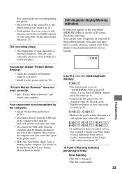
...Handycam Station or your camcorder securely (p. 9). The recording stops. • The temperature of times, contact your Sony dealer or local authorized Sony service facility. For details on the LCD screen, check the following. If the problem persists even after you cannot service has occurred. You cannot make new recording during this period. • The hard disk... of your camcorder. Delete unnecessary images (p. 25). • Total number of movie scenes or still images exceeds the recordable capacity of the camcorder is extremely high/low. Your camcorder is not ...
...Handycam Station or your camcorder securely (p. 9). The recording stops. • The temperature of times, contact your Sony dealer or local authorized Sony service facility. For details on the LCD screen, check the following. If the problem persists even after you cannot service has occurred. You cannot make new recording during this period. • The hard disk... of your camcorder. Delete unnecessary images (p. 25). • Total number of movie scenes or still images exceeds the recordable capacity of the camcorder is extremely high/low. Your camcorder is not ...

Operating Guide
Page 38
... 0 °C to + 40 °C (32 °F to 104 °F) Storage temperature -20 °C to + 60 °C (-4 °F to + 140 °F) 38 Dimensions (approx.) HDR-SR5: 75 × 81 × 135 mm (3 × 3 1/4 × 5 3/8 in.) (w/h/d) including the projecting parts 75 × 81 × 140 mm (3 × 3 1/4 ×...approx.) HDR-SR5: 460 g (1 lb) main unit only 540 g (1 lb 3 oz) including the NP-FH60 rechargeable battery pack HDR-SR7/SR8: 530 g (1 lb 2 oz) main unit only 610 g (1 lb 5 oz) including the NP-FH60 rechargeable battery pack Supplied accessories See page 8. Handycam Station DCRA...
... 0 °C to + 40 °C (32 °F to 104 °F) Storage temperature -20 °C to + 60 °C (-4 °F to + 140 °F) 38 Dimensions (approx.) HDR-SR5: 75 × 81 × 135 mm (3 × 3 1/4 × 5 3/8 in.) (w/h/d) including the projecting parts 75 × 81 × 140 mm (3 × 3 1/4 ×...approx.) HDR-SR5: 460 g (1 lb) main unit only 540 g (1 lb 3 oz) including the NP-FH60 rechargeable battery pack HDR-SR7/SR8: 530 g (1 lb 2 oz) main unit only 610 g (1 lb 5 oz) including the NP-FH60 rechargeable battery pack Supplied accessories See page 8. Handycam Station DCRA...

Service Manual
Page 2
...1 13/16 in this format can have additional information such as your camcorder's setting information at the time of recording. *2 The unique pixel array of Sony's ClearVid CMOS sensor and image processing system (new Enhanced Imaging Processor) ...AVCHD (HD)/MPEG2 (SD)/JPEG (Still images) Audio compression format Dolby Digital 2/5.1ch Dolby Digital 5.1 Creator Video signal PAL color, CCIR standards 1080/50i specification Hard disk HDR-SR5E: 40 GB HDR-SR7E: 60 GB HDR-SR8E: 100 GB When measuring media capacity, 1 GB equals 1 billion bytes, a portion of HDR-SR5E/SR7E/SR8E. CD-ROM "Handycam...
...1 13/16 in this format can have additional information such as your camcorder's setting information at the time of recording. *2 The unique pixel array of Sony's ClearVid CMOS sensor and image processing system (new Enhanced Imaging Processor) ...AVCHD (HD)/MPEG2 (SD)/JPEG (Still images) Audio compression format Dolby Digital 2/5.1ch Dolby Digital 5.1 Creator Video signal PAL color, CCIR standards 1080/50i specification Hard disk HDR-SR5E: 40 GB HDR-SR7E: 60 GB HDR-SR8E: 100 GB When measuring media capacity, 1 GB equals 1 billion bytes, a portion of HDR-SR5E/SR7E/SR8E. CD-ROM "Handycam...

Service Manual
Page 3
... can have additional information such as your camcorder's setting information at load impedance 47 kΩ...to change without notice. Supplied accessories AC Adaptor (1) Mains lead (1) Handycam Station (1) Component video cable (1) A/V connecting cable (1) USB cable (1) ...AVCHD (HD)/MPEG2 (SD)/JPEG (Still images) Audio compression format Dolby Digital 2/5.1ch Dolby Digital 5.1 Creator Video signal NTSC color, EIA standards 1080/60i specification Hard disk HDR-SR5: 40 GB HDR-SR5C: 100 GB HDR-SR7: 60 GB HDR-SR8: 100 GB When measuring media capacity, 1 GB equals 1 billion bytes, a portion of Sony...
... can have additional information such as your camcorder's setting information at load impedance 47 kΩ...to change without notice. Supplied accessories AC Adaptor (1) Mains lead (1) Handycam Station (1) Component video cable (1) A/V connecting cable (1) USB cable (1) ...AVCHD (HD)/MPEG2 (SD)/JPEG (Still images) Audio compression format Dolby Digital 2/5.1ch Dolby Digital 5.1 Creator Video signal NTSC color, EIA standards 1080/60i specification Hard disk HDR-SR5: 40 GB HDR-SR5C: 100 GB HDR-SR7: 60 GB HDR-SR8: 100 GB When measuring media capacity, 1 GB equals 1 billion bytes, a portion of Sony...

Service Manual
Page 47
... PR 17 CTRL1 21 CTRL2 23 CTRL3 25 USB_D+ 34 USB_D- 36 DET 19 MULTI_JACK_IN 26 PON(DVD-BURN) 37 LANC_DC 33 LANC_SIG 31 CRADLE (Handycam Station) FP-726 JK-342 BOARD FLEXIBLE BOARD CN1026 VIDEO_I/O 6 S_C_I/O 4 S_Y_I/O 2 AUDIO_L_I/O 14 AUDIO_R_I/O 12 JACK_AD 9 LANC_DC 8 LANC_SIG 10 CN7303 ... (PHOTO FREEZE) S004 (PHOTO REC) PHOTO OFF (CHG) ON POWER MODE D002 (CHARGE/STROBE) *1 SR5/SR5C SR5E R1076 XX 0 R1077 0 XX SR7/SR8 100K 22K SR7E/SR8E 22K 100K 08 HDR-SR5/SR5C/SR5E/SR7/SR7E/SR8/SR8E_L2 3-4 XCAM_LED 15 XCAM_LED HDD_ACCESS 12 X_ACCESS_LED D004 (CAM) D001 (ACCESS) OVERALL...
... PR 17 CTRL1 21 CTRL2 23 CTRL3 25 USB_D+ 34 USB_D- 36 DET 19 MULTI_JACK_IN 26 PON(DVD-BURN) 37 LANC_DC 33 LANC_SIG 31 CRADLE (Handycam Station) FP-726 JK-342 BOARD FLEXIBLE BOARD CN1026 VIDEO_I/O 6 S_C_I/O 4 S_Y_I/O 2 AUDIO_L_I/O 14 AUDIO_R_I/O 12 JACK_AD 9 LANC_DC 8 LANC_SIG 10 CN7303 ... (PHOTO FREEZE) S004 (PHOTO REC) PHOTO OFF (CHG) ON POWER MODE D002 (CHARGE/STROBE) *1 SR5/SR5C SR5E R1076 XX 0 R1077 0 XX SR7/SR8 100K 22K SR7E/SR8E 22K 100K 08 HDR-SR5/SR5C/SR5E/SR7/SR7E/SR8/SR8E_L2 3-4 XCAM_LED 15 XCAM_LED HDD_ACCESS 12 X_ACCESS_LED D004 (CAM) D001 (ACCESS) OVERALL...

Service Manual
Page 51
...504 BOARD (1/3) CN1009 ACV_UNREG_CN 3-8 BATT/XEXT 1 BATT/XEXT_CN Q4601, Q4603 Q4604, Q4610 FP-718 FLEXIBLE BOARD CN7181 35 CN1013 BATT/XEXT_CR 7 D4601 CRADLE (Handycam Station) 30 USB_DET 1-4 36 - 44 ACV_UNREG_CN 24 USB_VCC B POWER (3/3) (PAGE 3-10) D4605 BATT/XEXT Q4608 BATT DETECT FAST_CHARGE INIT_CHARGE_ON F4601 F4602 F4603 F4605...POWER SUPPLY (20/21) DVDD1 A1 DVDD2 A12 VB B1 OUT11 R15 PVDD8a PVDD8b LX8a LX8b B6, A6 B5, A5 IN8 C7 08 HDR-SR5/SR5C/SR5E/SR7/SR7E/SR8/SR8E_L2 G1, D1, D2 K13, L13, M13 P11_SO1 DIN P12_SCK1 HI_EVER_SO, HI_EVER_SCK, XCS_DD CLK P21_PPG01 LD ...
...504 BOARD (1/3) CN1009 ACV_UNREG_CN 3-8 BATT/XEXT 1 BATT/XEXT_CN Q4601, Q4603 Q4604, Q4610 FP-718 FLEXIBLE BOARD CN7181 35 CN1013 BATT/XEXT_CR 7 D4601 CRADLE (Handycam Station) 30 USB_DET 1-4 36 - 44 ACV_UNREG_CN 24 USB_VCC B POWER (3/3) (PAGE 3-10) D4605 BATT/XEXT Q4608 BATT DETECT FAST_CHARGE INIT_CHARGE_ON F4601 F4602 F4603 F4605...POWER SUPPLY (20/21) DVDD1 A1 DVDD2 A12 VB B1 OUT11 R15 PVDD8a PVDD8b LX8a LX8b B6, A6 B5, A5 IN8 C7 08 HDR-SR5/SR5C/SR5E/SR7/SR7E/SR8/SR8E_L2 G1, D1, D2 K13, L13, M13 P11_SO1 DIN P12_SCK1 HI_EVER_SO, HI_EVER_SCK, XCS_DD CLK P21_PPG01 LD ...

Service Manual
Page 54
... CN1004 1 2 CN1001 17 18 CPC (For Check) 40 1 FP-515 FLEXIBLE BOARD 51 1 HARD DISK DRIVE HDR-SR5/SR5C/SR5E/SR7/SR7E/SR8/SR8E_L2 4-1 FRAME PRINTED WIRING BOARDS AND SCHEMATIC DIAGRAMS 4-1. Ver. 1.1 2007.06 4. HDR-SR5/SR5C/SR5E ST-175 BOARD (SIDE A) ST-175 BOARD (SIDE B) LENS BLOCK 14 CN5202 2 ...(SIDE A) MS-374 BOARD (SIDE B) BT7401 LITHIUM SECONDARY BATTERY J7212 DC IN J7211 REMOTE JACK FP-721 FLEXIBLE BOARD 45 44 TO CRADLE (Handycam Station) 1 2 CN7181 41 42 FP-718 FLEXIBLE BOARD LEVEL3 CM-076 BOARD (SIDE B) 1 31 CN6801 30 32 IC6901 (not supplied) LEVEL3 CM...
... CN1004 1 2 CN1001 17 18 CPC (For Check) 40 1 FP-515 FLEXIBLE BOARD 51 1 HARD DISK DRIVE HDR-SR5/SR5C/SR5E/SR7/SR7E/SR8/SR8E_L2 4-1 FRAME PRINTED WIRING BOARDS AND SCHEMATIC DIAGRAMS 4-1. Ver. 1.1 2007.06 4. HDR-SR5/SR5C/SR5E ST-175 BOARD (SIDE A) ST-175 BOARD (SIDE B) LENS BLOCK 14 CN5202 2 ...(SIDE A) MS-374 BOARD (SIDE B) BT7401 LITHIUM SECONDARY BATTERY J7212 DC IN J7211 REMOTE JACK FP-721 FLEXIBLE BOARD 45 44 TO CRADLE (Handycam Station) 1 2 CN7181 41 42 FP-718 FLEXIBLE BOARD LEVEL3 CM-076 BOARD (SIDE B) 1 31 CN6801 30 32 IC6901 (not supplied) LEVEL3 CM...

Service Manual
Page 55
Ver. 1.1 2007.06 4-1-2. HDR-SR7/SR7E/SR8/SR8E ST-175 BOARD (SIDE A) 14 CN5202 2 13 1 ST-175 BOARD (SIDE B) FLASH UNIT (FL25500) ...374 BOARD (SIDE A) MS-374 BOARD (SIDE B) BT7401 LITHIUM SECONDARY BATTERY J7212 DC IN J7211 REMOTE JACK FP-721 FLEXIBLE BOARD TO CRADLE (Handycam Station) 1 2 CN7181 41 42 LEVEL3 CM-077 BOARD (SIDE B) IC6701 (not supplied) FP-718 FLEXIBLE BOARD 51 1 1 41 CN6601 40 ...24 24 16 CN1020 1 CN1001 17 2 18 CPC (For Check) MIC901 MICROPHONE UNIT 40 1 FP-515 FLEXIBLE BOARD 51 1 HARD DISK DRIVE HDR-SR5/SR5C/SR5E/SR7/SR7E/SR8/SR8E_L2 4-2 FRAME
Ver. 1.1 2007.06 4-1-2. HDR-SR7/SR7E/SR8/SR8E ST-175 BOARD (SIDE A) 14 CN5202 2 13 1 ST-175 BOARD (SIDE B) FLASH UNIT (FL25500) ...374 BOARD (SIDE A) MS-374 BOARD (SIDE B) BT7401 LITHIUM SECONDARY BATTERY J7212 DC IN J7211 REMOTE JACK FP-721 FLEXIBLE BOARD TO CRADLE (Handycam Station) 1 2 CN7181 41 42 LEVEL3 CM-077 BOARD (SIDE B) IC6701 (not supplied) FP-718 FLEXIBLE BOARD 51 1 1 41 CN6601 40 ...24 24 16 CN1020 1 CN1001 17 2 18 CPC (For Check) MIC901 MICROPHONE UNIT 40 1 FP-515 FLEXIBLE BOARD 51 1 HARD DISK DRIVE HDR-SR5/SR5C/SR5E/SR7/SR7E/SR8/SR8E_L2 4-2 FRAME


