
Service Manual
Page 1
... Type KSS-213D/Q-NP Model Name Using Similar Mechanism MDS-JE520 Mechanism Type MDM-5A Optical Pick-up Type KMS-260A/K1NP Model Name Using Similar Mechanism HCD-DR4/DR5/DR6/DR440/ W300/W5000/XB500 Tape Transport Mechanism Type TCM-230AWR2/230PWR2 SPECIFICATIONS - HCD-MDX10 SERVICE MANUAL Ver 1.1 2001. 06 US Model Canadian Model AEP Model UK Model E Model Australian Model HCD-MDX10 is the tuner, deck, CD, MD and amplifier section in MHC-MDX10.
... Type KSS-213D/Q-NP Model Name Using Similar Mechanism MDS-JE520 Mechanism Type MDM-5A Optical Pick-up Type KMS-260A/K1NP Model Name Using Similar Mechanism HCD-DR4/DR5/DR6/DR440/ W300/W5000/XB500 Tape Transport Mechanism Type TCM-230AWR2/230PWR2 SPECIFICATIONS - HCD-MDX10 SERVICE MANUAL Ver 1.1 2001. 06 US Model Canadian Model AEP Model UK Model E Model Australian Model HCD-MDX10 is the tuner, deck, CD, MD and amplifier section in MHC-MDX10.

Service Manual
Page 7
..., Power SW, CD Panel Boards and Display Board 17 3-5. Disc Tray 18 3-6. Chassis Section 120 9-3. MD Mechanism Section-1 (MDM-5A 127 9-10. TEST MODE (MD 22 6. Schematic Diagram - Main Section 75 8-13. Deck Section 79 8-15. Schematic Diagram - Printed Wiring Board - Printed Wiring Board - Schematic Diagram - BD Switch Section 96 8-25. CD Motor Section 99 8-27. Schematic Diagram - IC Block Diagrams 109 8-32. IC Pin Functions 112 - 7 - SERVICING NOTE 8 2. CD Mechanism Deck...
..., Power SW, CD Panel Boards and Display Board 17 3-5. Disc Tray 18 3-6. Chassis Section 120 9-3. MD Mechanism Section-1 (MDM-5A 127 9-10. TEST MODE (MD 22 6. Schematic Diagram - Main Section 75 8-13. Deck Section 79 8-15. Schematic Diagram - Printed Wiring Board - Printed Wiring Board - Schematic Diagram - BD Switch Section 96 8-25. CD Motor Section 99 8-27. Schematic Diagram - IC Block Diagrams 109 8-32. IC Pin Functions 112 - 7 - SERVICING NOTE 8 2. CD Mechanism Deck...

Service Manual
Page 20
... preset data stored in and out. Each time a button is activated. 3. To exit from this mode, perform as if the power cord is plugged in the RAM to turn the set . CD Delivery Mode • This mode moves the optical pick-up to select the BAND "AM". 3. Use this mode when returning the set to turn the set ON. 2. Press 1/u button to the customer after repair. MC Hot Reset • This mode resets...
... preset data stored in and out. Each time a button is activated. 3. To exit from this mode, perform as if the power cord is plugged in the RAM to turn the set . CD Delivery Mode • This mode moves the optical pick-up to select the BAND "AM". 3. Use this mode when returning the set to turn the set ON. 2. Press 1/u button to the customer after repair. MC Hot Reset • This mode resets...

Service Manual
Page 23
... adjustment Laser power adjustment Traverse (MO) adjustment Traverse (CD) adjustment Focus bias adjustment Non-volatile memory control Command transmission Status display Error history display, clear Sled check Access check Outermost circumference check Head position check Same functions as CPLAY MODE Same functions as CREC MODE Initialization of non-volatile memory of adjustment value Auto gain output level adjustment (MO) Auto gain output level adjustment (CD) IOP data display IOP data write Microprocessing version display Continuous play mode...
... adjustment Laser power adjustment Traverse (MO) adjustment Traverse (CD) adjustment Focus bias adjustment Non-volatile memory control Command transmission Status display Error history display, clear Sled check Access check Outermost circumference check Head position check Same functions as CPLAY MODE Same functions as CREC MODE Initialization of non-volatile memory of adjustment value Auto gain output level adjustment (MO) Auto gain output level adjustment (CD) IOP data display IOP data write Microprocessing version display Continuous play mode...
Service Manual
Page 28
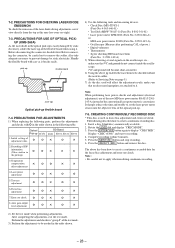
... adjustment ¬ ¬ G ¬ G 6. Error rate check ¬ ¬ G ¬ G 8. Auto gain output level adjustment ¬ ¬ G ¬ G 2) Set the test mode when performing adjustments. Display "CREC (0300)" and start to display "CREC MID". The above jig enables the waveform to create a continuous recording disc. 1. PRECAUTIONS FOR ADJUSTMENTS 1) When replacing the following tools and measuring devices. • Check Disc (MD) TDYS-1 (Parts No. 4-963-646-01) • Test Disk...
... adjustment ¬ ¬ G ¬ G 6. Error rate check ¬ ¬ G ¬ G 8. Auto gain output level adjustment ¬ ¬ G ¬ G 2) Set the test mode when performing adjustments. Display "CREC (0300)" and start to display "CREC MID". The above jig enables the waveform to create a continuous recording disc. 1. PRECAUTIONS FOR ADJUSTMENTS 1) When replacing the following tools and measuring devices. • Check Disc (MD) TDYS-1 (Parts No. 4-963-646-01) • Test Disk...

Service Manual
Page 29
... the optical pick-up objective lens Digital volt meter Note 1: After step 4, each time the ENTER/YES button is satisfied. BI X 100 2 (A + B) 9. Then, the optical pick-up . (Refer to be displayed. 7-6. Rotate the AMS dial to Parts Replacement and Adjustments" (See page 11). 7-6-1. Connect an oscilloscope to 0.92 mW. 4. Load a disc (any available on the objective lens of the laser power meter...
... the optical pick-up objective lens Digital volt meter Note 1: After step 4, each time the ENTER/YES button is satisfied. BI X 100 2 (A + B) 9. Then, the optical pick-up . (Refer to be displayed. 7-6. Rotate the AMS dial to Parts Replacement and Adjustments" (See page 11). 7-6-1. Connect an oscilloscope to 0.92 mW. 4. Load a disc (any available on the objective lens of the laser power meter...

Service Manual
Page 31
... "Iop Write". To save the adjustment results. ("LD SAVE $ " will be displayed for the 6 value. Recording and Displaying IOP Information.) Connection : Laser power meter Optical pick-up . Rotate the AMS dial and display "LDPWR ADJUST". (Laser power : For adjustment) 3. Setting Procedure : 1. "Complete!" Recording Procedure : 1. To select the digit : Press the MD MALKMAN SYNC button. 6. When D101 has been replaced, perform this adjustment in an ambient temperature of...
... "Iop Write". To save the adjustment results. ("LD SAVE $ " will be displayed for the 6 value. Recording and Displaying IOP Information.) Connection : Laser power meter Optical pick-up . Rotate the AMS dial and display "LDPWR ADJUST". (Laser power : For adjustment) 3. Setting Procedure : 1. "Complete!" Recording Procedure : 1. To select the digit : Press the MD MALKMAN SYNC button. 6. When D101 has been replaced, perform this adjustment in an ambient temperature of...

Service Manual
Page 37
... adjustment level as follows. Adjust RV1002 of the LEAF SW board so that adjustment within ± 0.5 dB Adjustment Location: AUDIO board Record Bias Adjustment (Deck B) Procedure: INTRODUCTION When set to double speed or normal speed each time the HI DUB button is set 4. During recording, the input signal FUNCTION will automatically switch to VIDEO. (After recording, press the - 0 button without stopping will switch to the test mode performed in Tape Speed Adjustment, when...
... adjustment level as follows. Adjust RV1002 of the LEAF SW board so that adjustment within ± 0.5 dB Adjustment Location: AUDIO board Record Bias Adjustment (Deck B) Procedure: INTRODUCTION When set to double speed or normal speed each time the HI DUB button is set 4. During recording, the input signal FUNCTION will automatically switch to VIDEO. (After recording, press the - 0 button without stopping will switch to the test mode performed in Tape Speed Adjustment, when...

Service Manual
Page 38
... is set. Press FUNCTION button to select VIDEO 1. (This step is convenient for performing this adjustment. Mode: Record VIDEO (AUDIO) IN 315Hz 50 mV (-23.8 dB) AF OSC 600 Ω attenuator blank tape CS-123 set VIDEO (AUDIO) OUT 5. Adjustment level: CN403 playback level: 47.2 to 53.0 mV (-24.3 to the position where recording was started.) 1. Mode: Playback recorded position level meter set 4. Insert a tape into deck B, press the r REC button, and...
... is set. Press FUNCTION button to select VIDEO 1. (This step is convenient for performing this adjustment. Mode: Record VIDEO (AUDIO) IN 315Hz 50 mV (-23.8 dB) AF OSC 600 Ω attenuator blank tape CS-123 set VIDEO (AUDIO) OUT 5. Adjustment level: CN403 playback level: 47.2 to 53.0 mV (-24.3 to the position where recording was started.) 1. Mode: Playback recorded position level meter set 4. Insert a tape into deck B, press the r REC button, and...
Service Manual
Page 39
... neutral detergent when the signal level is low than specified value with lead wires. 3. With the disc (YEDS-18) loaded, press the ^ button and perform focus search. (Focus search will be clearly distinguished at this time. Check the symmetry and peak to turn the unit ON. 3. Procedure: 1. Connect oscilloscope to turn the set ON. 4. Press the 1/u button to test point TP (TE) on...
... neutral detergent when the signal level is low than specified value with lead wires. 3. With the disc (YEDS-18) loaded, press the ^ button and perform focus search. (Focus search will be clearly distinguished at this time. Check the symmetry and peak to turn the unit ON. 3. Procedure: 1. Connect oscilloscope to turn the set ON. 4. Press the 1/u button to test point TP (TE) on...

Service Manual
Page 40
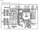
... (Digital out) IC101 DIGITAL SERVO DIGITAL SIGNAL PROCESSOR 51 RF AC 16K RAM EFM DEMODULATION DATA BUS ERROR CORRECTOR D/A INTERFACE TIMING LOGIC XTA1 66 STAO 67 DIGITAL OUT D OUT 60 X101 16.9344MHz DOUT INTEGRATOR 49 ASY1 48 ASY0 ASYMMETRY CORRECTION DIGITAL PLL VC INTEGRATOR VC 38 CE 42 RFDC 43 FE 39 TE 41 SE 40 OPERATIONAL AMPLIFIER ANALOG SWITCH A/D CONVERTER...
... (Digital out) IC101 DIGITAL SERVO DIGITAL SIGNAL PROCESSOR 51 RF AC 16K RAM EFM DEMODULATION DATA BUS ERROR CORRECTOR D/A INTERFACE TIMING LOGIC XTA1 66 STAO 67 DIGITAL OUT D OUT 60 X101 16.9344MHz DOUT INTEGRATOR 49 ASY1 48 ASY0 ASYMMETRY CORRECTION DIGITAL PLL VC INTEGRATOR VC 38 CE 42 RFDC 43 FE 39 TE 41 SE 40 OPERATIONAL AMPLIFIER ANALOG SWITCH A/D CONVERTER...

Service Manual
Page 43
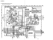
... 36 POWER 2 CD POWER 5 FL SW 42 STBY RELAY 43 X601 32.768KHz STK MUTE 1 PROTECTOR ON 27 J191 SUPER WOOFER - 48 - L TBL. HCD-MDX10 D IN 0 D IN 1 IIC DATA IIC CLK P. MAIN SECTION - MIC IN SW (TO DISPLAY SECTION) RV712 MIC J711 LEVEL MIX MIC IC712(1/2) IC712(2/2) DIGITAL OPTICAL R-CH IC382 OPT IN 30 D OUT IC381 SELECT BD (MD) SECTION (2) (DIGITAL) IC202 D IN 1 2 VIDEO/IN J102 (AUDIO...
... 36 POWER 2 CD POWER 5 FL SW 42 STBY RELAY 43 X601 32.768KHz STK MUTE 1 PROTECTOR ON 27 J191 SUPER WOOFER - 48 - L TBL. HCD-MDX10 D IN 0 D IN 1 IIC DATA IIC CLK P. MAIN SECTION - MIC IN SW (TO DISPLAY SECTION) RV712 MIC J711 LEVEL MIX MIC IC712(1/2) IC712(2/2) DIGITAL OPTICAL R-CH IC382 OPT IN 30 D OUT IC381 SELECT BD (MD) SECTION (2) (DIGITAL) IC202 D IN 1 2 VIDEO/IN J102 (AUDIO...

Service Manual
Page 47
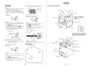
... FOR PRINTED WIRING BOARDS AND SCHEMATIC DIAGRAMS. (In addition to this, the necessary note is printed in each block.) For schematic diagrams. Note: • All capacitors are omitted WAVEFORMS - Voltage variations may be noted due to normal production tolerances. • Circled numbers refer to waveforms. • Signal path. Note: • X : parts extracted from the component side. • p : parts mounted on...
... FOR PRINTED WIRING BOARDS AND SCHEMATIC DIAGRAMS. (In addition to this, the necessary note is printed in each block.) For schematic diagrams. Note: • All capacitors are omitted WAVEFORMS - Voltage variations may be noted due to normal production tolerances. • Circled numbers refer to waveforms. • Signal path. Note: • X : parts extracted from the component side. • p : parts mounted on...
Service Manual
Page 52
BD (MD) (2/2) SECTION - • See page 56 for Waveforms. • See page 109 for IC Block Diagrams. • See page 113 for IC Pin Functions. (Page 63) (Page 63) (Page 63) (Page 64) (Page 64) (Page 64) (Page 64) (Page 93) (Page 93) - 65 - BA033FP-E2 - 66 - HCD-MDX10 8-7. SCHEMATIC DIAGRAM -
BD (MD) (2/2) SECTION - • See page 56 for Waveforms. • See page 109 for IC Block Diagrams. • See page 113 for IC Pin Functions. (Page 63) (Page 63) (Page 63) (Page 64) (Page 64) (Page 64) (Page 64) (Page 93) (Page 93) - 65 - BA033FP-E2 - 66 - HCD-MDX10 8-7. SCHEMATIC DIAGRAM -
Service Manual
Page 54
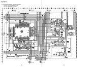
MAIN (2/4) SECTION - • See page 75 for Printed Wiring Board. (Page 68) (Page 68) (Page 73) - 69 - (Page 74) (Page 74) (Page 104) (Page 74) - 70 - SCHEMATIC DIAGRAM - HCD-MDX10 8-9.
MAIN (2/4) SECTION - • See page 75 for Printed Wiring Board. (Page 68) (Page 68) (Page 73) - 69 - (Page 74) (Page 74) (Page 104) (Page 74) - 70 - SCHEMATIC DIAGRAM - HCD-MDX10 8-9.
Service Manual
Page 56
MAIN (4/4) SECTION - • See page 75 for Printed Wiring Board. • See page 116 for IC Pin Functions. (Page 68) (Page 72) (Page 69) (Page 72) (Page 69) (Page 70) (Page 70) (Page 72) - 73 - (Page 106) (Page 84) - 74 - SCHEMATIC DIAGRAM - HCD-MDX10 8-11.
MAIN (4/4) SECTION - • See page 75 for Printed Wiring Board. • See page 116 for IC Pin Functions. (Page 68) (Page 72) (Page 69) (Page 72) (Page 69) (Page 70) (Page 70) (Page 72) - 73 - (Page 106) (Page 84) - 74 - SCHEMATIC DIAGRAM - HCD-MDX10 8-11.

Service Manual
Page 76
... signal input "L": Stand by 20 F0CNT Center frequency control voltage input of the ADIP amplifier 44 OPO O User operation amplifier output (Not used ) 22 EQADJ I/O Center frequency setting pin for the internal circuit EQ 23 3TADJ I/O Center frequency setting pin for the internal circuit BPF22 26 TE O Tracking error signal output to the CXD2650R or CXD2652AR O (Switching with AC coupling 48 MORFO O Groove RF signal output • Abbreviation APC: Auto Power Control AGC: Auto Gain Control - 112 - IC PIN FUNCTIONS...
... signal input "L": Stand by 20 F0CNT Center frequency control voltage input of the ADIP amplifier 44 OPO O User operation amplifier output (Not used ) 22 EQADJ I/O Center frequency setting pin for the internal circuit EQ 23 3TADJ I/O Center frequency setting pin for the internal circuit BPF22 26 TE O Tracking error signal output to the CXD2650R or CXD2652AR O (Switching with AC coupling 48 MORFO O Groove RF signal output • Abbreviation APC: Auto Power Control AGC: Auto Gain Control - 112 - IC PIN FUNCTIONS...

Service Manual
Page 77
... signal output to the system control 9 SENS O (3) Internal status (SENSE) output to the system control 10 XRST I Data input from the system control "L": Reset 11 SQSY Subcode Q sync (SCOR) output to A08 O DRAM address output 41 A11 O DRAM address output (Not used ) 18 XTSL I System clock frequency setting "L": 45.1584 MHz, "H": 22.5792 MHz (Fixed at "H") 19 DIN0 I Digital audio input (Optical input) 20 DIN1 I Digital audio input (Optical input) 21 DOUT O Digital audio output (Optical output) 22 DADTI I Serial data input...
... signal output to the system control 9 SENS O (3) Internal status (SENSE) output to the system control 10 XRST I Data input from the system control "L": Reset 11 SQSY Subcode Q sync (SCOR) output to A08 O DRAM address output 41 A11 O DRAM address output (Not used ) 18 XTSL I System clock frequency setting "L": 45.1584 MHz, "H": 22.5792 MHz (Fixed at "H") 19 DIN0 I Digital audio input (Optical input) 20 DIN1 I Digital audio input (Optical input) 21 DOUT O Digital audio output (Optical output) 22 DADTI I Serial data input...

Service Manual
Page 80
... (32.768MHz) O 12 RESET 13 X-OUT I Speaker protect ON/OF 28 - - Not used I 42 FL-SW I FL switch ON/OFF 43 STBY RELAY I Digital input selector 47 493-DATA 48 493-CLK O Data output for M62493FP (IC101) O Clock output for SYNC bass 45 - - O DBFB H/L select signal output - Not used ) 26 TIMER LED I Timer LED ON/OF 27 PROTECTOR ON I Reset signal input O X'tal (16MHz) 14 VSS - Power supply (+5V) 17...
... (32.768MHz) O 12 RESET 13 X-OUT I Speaker protect ON/OF 28 - - Not used I 42 FL-SW I FL switch ON/OFF 43 STBY RELAY I Digital input selector 47 493-DATA 48 493-CLK O Data output for M62493FP (IC101) O Clock output for SYNC bass 45 - - O DBFB H/L select signal output - Not used ) 26 TIMER LED I Timer LED ON/OF 27 PROTECTOR ON I Reset signal input O X'tal (16MHz) 14 VSS - Power supply (+5V) 17...
Service Manual
Page 93
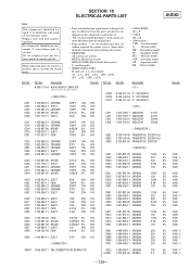
... < CONNECTOR > Ref. SECTION 10 ELECTRICAL PARTS LIST AUDIO Note: The components identified by reference number, please include the board name. • Due to standardization, replacements in the parts list may be anticipated when ordering these items. • RESISTORS All resistors are in the diagrams or the components used on the set. • -XX, -X mean standardized parts, so they may have some...
... < CONNECTOR > Ref. SECTION 10 ELECTRICAL PARTS LIST AUDIO Note: The components identified by reference number, please include the board name. • Due to standardization, replacements in the parts list may be anticipated when ordering these items. • RESISTORS All resistors are in the diagrams or the components used on the set. • -XX, -X mean standardized parts, so they may have some...


