

Service Manual
Page 1
...distortion from 250 milliwatts to rated output. Inputs (Analog) Inputs (Digital) Outputs (Analog) VIDEO 1, 2: Sensitivity: 150 mV Impedance: 50 kilohms VIDEO 2 (optical): Sensitivity: - AUDIO POWER SPECIFICATIONS (C990: US model) POWER OUTPUT AND TOTAL HARMONIC DISTORTION: With 3 ohm loads, both channels .../DVD RECEIVER 9-874-059-07 2004I05-1 © 2004.09 Sony Corporation Audio Group Published by Sony Engineering Corporation HCD-C770/C990 SERVICE MANUAL Ver 1.6 2004.09 US Model Canadian Model HCD-C770/C990 AEP Model Australian Model HCD-C770 HCD-C770/C990 is the amplifier, DVD/...
...distortion from 250 milliwatts to rated output. Inputs (Analog) Inputs (Digital) Outputs (Analog) VIDEO 1, 2: Sensitivity: 150 mV Impedance: 50 kilohms VIDEO 2 (optical): Sensitivity: - AUDIO POWER SPECIFICATIONS (C990: US model) POWER OUTPUT AND TOTAL HARMONIC DISTORTION: With 3 ohm loads, both channels .../DVD RECEIVER 9-874-059-07 2004I05-1 © 2004.09 Sony Corporation Audio Group Published by Sony Engineering Corporation HCD-C770/C990 SERVICE MANUAL Ver 1.6 2004.09 US Model Canadian Model HCD-C770/C990 AEP Model Australian Model HCD-C770 HCD-C770/C990 is the amplifier, DVD/...

Service Manual
Page 2
HCD-C770/C990 Super Audio CD/DVD system Laser Semiconductor laser (Super Audio CD/DVD: λ = 650 nm) (CD: λ = 780 nm) Emission duration: continuous Signal format system NTSC or NTSC/PAL Frequency response (at 2 CH STEREO mode) DVD...consumption (C770) Power consumption (C990) Dimensions (approx.) Mass (approx.) Operating temperature Operating humidity Video: 1 Vp-p 75 ohms Video: 1 Vp-p 75 ohms S video: Y: 1 Vp-p 75...prevent a malfunction, the system has performed the selfdiagnosis function. , Contact your nearest Sony dealer or local authorized Sony service facility and give the...
HCD-C770/C990 Super Audio CD/DVD system Laser Semiconductor laser (Super Audio CD/DVD: λ = 650 nm) (CD: λ = 780 nm) Emission duration: continuous Signal format system NTSC or NTSC/PAL Frequency response (at 2 CH STEREO mode) DVD...consumption (C770) Power consumption (C990) Dimensions (approx.) Mass (approx.) Operating temperature Operating humidity Video: 1 Vp-p 75 ohms Video: 1 Vp-p 75 ohms S video: Y: 1 Vp-p 75...prevent a malfunction, the system has performed the selfdiagnosis function. , Contact your nearest Sony dealer or local authorized Sony service facility and give the...

Service Manual
Page 4
...Section-5 (CDM69-DVBU16) ........ 117 8-12. Mechanism Deck Section-6 (CDM69-DVBU16) ........ 118 8-13. Optical Pick-up (DVBU16 13 3-10. HCD-C770/C990 Ver 1.5 TABLE OF CONTENTS SELF DIAGNOSIS FUNCTION 2 1. POWER SW Board 11 3-5. Motor (Stocker) Assy (Stocker) (M781 15 3-14. Block...(S702), Gear (Stocker Communication 21 4-6. AUDIO OUT, PANEL Section - ..... 34 7-4. CHANGER Section 41 7-11. Printed Wiring Board - DVD Board (3/10 46 7-16. DVD Board (10/10 53 7-23. Printed Wiring Boards - Schematic Diagram - VIDEO Section 60 7-30. DC-DC CONVERTER Section...
...Section-5 (CDM69-DVBU16) ........ 117 8-12. Mechanism Deck Section-6 (CDM69-DVBU16) ........ 118 8-13. Optical Pick-up (DVBU16 13 3-10. HCD-C770/C990 Ver 1.5 TABLE OF CONTENTS SELF DIAGNOSIS FUNCTION 2 1. POWER SW Board 11 3-5. Motor (Stocker) Assy (Stocker) (M781 15 3-14. Block...(S702), Gear (Stocker Communication 21 4-6. AUDIO OUT, PANEL Section - ..... 34 7-4. CHANGER Section 41 7-11. Printed Wiring Board - DVD Board (3/10 46 7-16. DVD Board (10/10 53 7-23. Printed Wiring Boards - Schematic Diagram - VIDEO Section 60 7-30. DC-DC CONVERTER Section...

Service Manual
Page 5
...signal codes of [DISC 1] and x simultaneously for the antitheft of different models. J-2501-217-A) extension cable (DVD board-AMP board) (Part No. SECTION 1 SERVICING NOTES HCD-C770/C990 Ver 1.6 NOTES ON HANDLING THE OPTICAL PICK-UP BLOCK OR BASE UNIT The laser diode in the store is ...The message "UNLOCKED" is displayed and the slot is not set the "DRIVE MANUAL OPERATION". (See page 26) 3. NOTE OF REPLACING THE DVD BOARD When replacing the DVD board, since the adjustment value is un- In this set the "2-6, Memory Check". (See page 28) 4. Procedure: 1. Press the [2]...
...signal codes of [DISC 1] and x simultaneously for the antitheft of different models. J-2501-217-A) extension cable (DVD board-AMP board) (Part No. SECTION 1 SERVICING NOTES HCD-C770/C990 Ver 1.6 NOTES ON HANDLING THE OPTICAL PICK-UP BLOCK OR BASE UNIT The laser diode in the store is ...The message "UNLOCKED" is displayed and the slot is not set the "DRIVE MANUAL OPERATION". (See page 26) 3. NOTE OF REPLACING THE DVD BOARD When replacing the DVD board, since the adjustment value is un- In this set the "2-6, Memory Check". (See page 28) 4. Procedure: 1. Press the [2]...

Service Manual
Page 6
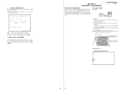
HCD-C770/C990 LOCATION OF CONTROLS Front Panel SECTION 2 GENERAL This section is extracted from instruction manual. STANDBY FUNCTION BAND ...VIDEO 1 AUDIO OUT R L VIDEO OUT R L AUDIO IN VIDEO IN COMPONENT SCAN SELECT VIDEO OUT MONITOR OUT VIDEO 2 VIDEO S VIDEO AUDIO IN R L VIDEO IN SELECTABLE INTERLACE DVD ONLY OPTICAL DIGITAL IN Y P B/CB PR/CR COMPONENT VIDEO OUT VIDEO 2 1 SPEAKER jacks 2 AM antenna 3 VIDEO 1 jacks 4 VIDEO 2 jacks 5 COMPONENT VIDEO OUT/SCAN SELECT switch 6 MONITOR OUT (VIDEO/S VIDEO) jacks 7 VIDEO 2 (OPTICAL DIGITAL IN) jack 8 COMPONENT VIDEO...
HCD-C770/C990 LOCATION OF CONTROLS Front Panel SECTION 2 GENERAL This section is extracted from instruction manual. STANDBY FUNCTION BAND ...VIDEO 1 AUDIO OUT R L VIDEO OUT R L AUDIO IN VIDEO IN COMPONENT SCAN SELECT VIDEO OUT MONITOR OUT VIDEO 2 VIDEO S VIDEO AUDIO IN R L VIDEO IN SELECTABLE INTERLACE DVD ONLY OPTICAL DIGITAL IN Y P B/CB PR/CR COMPONENT VIDEO OUT VIDEO 2 1 SPEAKER jacks 2 AM antenna 3 VIDEO 1 jacks 4 VIDEO 2 jacks 5 COMPONENT VIDEO OUT/SCAN SELECT switch 6 MONITOR OUT (VIDEO/S VIDEO) jacks 7 VIDEO 2 (OPTICAL DIGITAL IN) jack 8 COMPONENT VIDEO...

Service Manual
Page 7
.../C990 Front Panel Display When playing back a DVD Current sound Playing status Current chapter number Lights up when you can change the angle PCM DIGITAL PRO LOGIC ALL1 DISC S TITLE CHAPTER Play mode Current title number Current surround format H M S ANGLE REPEAT 1 Playing time Current repeat mode When playing back a Super Audio CD, CD, VIDEO...
.../C990 Front Panel Display When playing back a DVD Current sound Playing status Current chapter number Lights up when you can change the angle PCM DIGITAL PRO LOGIC ALL1 DISC S TITLE CHAPTER Play mode Current title number Current surround format H M S ANGLE REPEAT 1 Playing time Current repeat mode When playing back a Super Audio CD, CD, VIDEO...

Service Manual
Page 8
...SELECT qf DVD TOP MENU qg DVD DISPLAY qh C/X/x/c/ENTER qj DVD SETUP qk 1 (standby) ql DISC SKIP w; SUBTITLE qa VOL +/- However, before glowing, the remote must be exposed to light for awhile. 1 TV [/1 (on/standby) 2 Z (EJECT) 3 NAME 4 STEREO/MONO 5 MEMORY 6 CLEAR 7 PLAY MODE 8 AUDIO 9 ANGLE q; TV/VIDEO wa ...REPEAT ws MUTING wd TIME wf FUNCTION wg BAND wh Number buttons wj SOUND FIELD wk DISPLAY wl ENTER e; HCD-C770/C990 Remote 123 456 7 89 >10 10/0 Note This remote control glows in the dark...
...SELECT qf DVD TOP MENU qg DVD DISPLAY qh C/X/x/c/ENTER qj DVD SETUP qk 1 (standby) ql DISC SKIP w; SUBTITLE qa VOL +/- However, before glowing, the remote must be exposed to light for awhile. 1 TV [/1 (on/standby) 2 Z (EJECT) 3 NAME 4 STEREO/MONO 5 MEMORY 6 CLEAR 7 PLAY MODE 8 AUDIO 9 ANGLE q; TV/VIDEO wa ...REPEAT ws MUTING wd TIME wf FUNCTION wg BAND wh Number buttons wj SOUND FIELD wk DISPLAY wl ENTER e; HCD-C770/C990 Remote 123 456 7 89 >10 10/0 Note This remote control glows in the dark...

Service Manual
Page 9
... the order shown below. 3-1. SW BOARD, BRACKET (TOP) ASSY (Page 14) 3-9. MOTOR (STOCKER) ASSY (ROLLER) (M771) (Page 16) 3-17. DVD BOARD (Page 13) 3-11. OPTICAL PICK-UP (DVBU16) (Page 13) 3-4. TIMING BELT (FRONT/REAR) (Page 17) 3-18. CAM (GEAR) (Page 18...(STOCKER) ASSY (MODE) (M761) (Page 16) 3-14. AMP BOARD (Page 12) 3-8. AUDIO BOARD, VIDEO BOARD (Page 11) 3-16. SENSOR BOARD (Page 18) 9 POWER SW BOARD (Page 11) 3-13. DISASSEMBLY FLOW SECTION 3 DISASSEMBLY HCD-C770/C990 SET 3-2. POWER BOARD (Page 12) 3-6. MOTOR (STOCKER) ASSY (STOCKER) (M781) (Page 15...
... the order shown below. 3-1. SW BOARD, BRACKET (TOP) ASSY (Page 14) 3-9. MOTOR (STOCKER) ASSY (ROLLER) (M771) (Page 16) 3-17. DVD BOARD (Page 13) 3-11. OPTICAL PICK-UP (DVBU16) (Page 13) 3-4. TIMING BELT (FRONT/REAR) (Page 17) 3-18. CAM (GEAR) (Page 18...(STOCKER) ASSY (MODE) (M761) (Page 16) 3-14. AMP BOARD (Page 12) 3-8. AUDIO BOARD, VIDEO BOARD (Page 11) 3-16. SENSOR BOARD (Page 18) 9 POWER SW BOARD (Page 11) 3-13. DISASSEMBLY FLOW SECTION 3 DISASSEMBLY HCD-C770/C990 SET 3-2. POWER BOARD (Page 12) 3-6. MOTOR (STOCKER) ASSY (STOCKER) (M781) (Page 15...

Service Manual
Page 13
3-8. DVD BOARD 1 two screws (BVTP3 × 8) 4 wire (flat type) (CN006) 9 DVD board HCD-C770/C990 3 2 two screws (BVTP3 × 8) 8 two screws (BVTP3 × 8) 5 wire (flat type) (CN002) 6 wire (flat type) (CN003) 7 wire (flat type) (CN401) 3-9. OPTICAL PICK-UP (DVBU16) 2 3 boss 5 boss 1 screw (PTPWHM2.6) 6 optical pick-up (DVBU16) 4 boss 13
3-8. DVD BOARD 1 two screws (BVTP3 × 8) 4 wire (flat type) (CN006) 9 DVD board HCD-C770/C990 3 2 two screws (BVTP3 × 8) 8 two screws (BVTP3 × 8) 5 wire (flat type) (CN002) 6 wire (flat type) (CN003) 7 wire (flat type) (CN401) 3-9. OPTICAL PICK-UP (DVBU16) 2 3 boss 5 boss 1 screw (PTPWHM2.6) 6 optical pick-up (DVBU16) 4 boss 13

Service Manual
Page 24
.... (At the bottom of the menu screen, the model name and revision number are given on the on test mode. Audio Check 0-2. All (All items continuous check) This menu checks all items are checked successively one after another automatically unless an ... PREV] button to DVD. 2. ROM Check Sum 0-2-4. EEPROM Check 0-3-1. Sampling Check 0-3-2. HCD-C770/C990 Ver 1.4 SECTION 5 TEST MODE [GENERAL DESCRIPTION] The Test Mode allows you must compare it with the specified value for the DVD system processor (IC206) is displayed. Drive Auto Adjustment 2. Video 7. General Description of...
.... (At the bottom of the menu screen, the model name and revision number are given on the on test mode. Audio Check 0-2. All (All items continuous check) This menu checks all items are checked successively one after another automatically unless an ... PREV] button to DVD. 2. ROM Check Sum 0-2-4. EEPROM Check 0-3-1. Sampling Check 0-3-2. HCD-C770/C990 Ver 1.4 SECTION 5 TEST MODE [GENERAL DESCRIPTION] The Test Mode allows you must compare it with the specified value for the DVD system processor (IC206) is displayed. Drive Auto Adjustment 2. Video 7. General Description of...

Service Manual
Page 25
...disc following the message displayed on the remote commander, and the servo set data in EEPROM will be initialized. Audio Check Output the test signal (1kHz sine wave) for adjustment. 1-0. DRIVE AUTO ADJUSTMENT On the Test Mode Menu...remote commander and insert a CD disc following the message. Then, 1. Note: During adjustment of the DVD system processor (IC206) pin 150, 151 and 154 (for video level adjustment. 0-7. Set disc type CD 5. Spindle start 16. Wait 500 msec 8. Wait 500... 11. Sled ON 25 Auto focus gain adjust 20. Spindle start ) 14. HCD-C770/C990 0-2-3.
...disc following the message displayed on the remote commander, and the servo set data in EEPROM will be initialized. Audio Check Output the test signal (1kHz sine wave) for adjustment. 1-0. DRIVE AUTO ADJUSTMENT On the Test Mode Menu...remote commander and insert a CD disc following the message. Then, 1. Note: During adjustment of the DVD system processor (IC206) pin 150, 151 and 154 (for video level adjustment. 0-7. Set disc type CD 5. Spindle start 16. Wait 500 msec 8. Wait 500... 11. Sled ON 25 Auto focus gain adjust 20. Spindle start ) 14. HCD-C770/C990 0-2-3.

Service Manual
Page 26
... Test Mode) x : Servo stop the servo operation, and press the [POWER] button to be written to Operation Menu or Test Mode Menu [. HCD-C770/C990 17. Auto focus gain adjust 21. Auto LFO Adjust 24. Then the adjustment will be made through the steps below, then adjusted values will be...Write Adjust 6. Auto focus offset adjust 38. Check CLV on 13. Tracking on 18. Auto focus gain adjust 18. Auto loop filter offset adjust 19. DVD Dual Layer Disc Adjustment Steps: 1. Check CLV lock 34. Non EEPROM Write Adjust 5. In case of an alarm, immediately press the x button to stop...
... Test Mode) x : Servo stop the servo operation, and press the [POWER] button to be written to Operation Menu or Test Mode Menu [. HCD-C770/C990 17. Auto focus gain adjust 21. Auto LFO Adjust 24. Then the adjustment will be made through the steps below, then adjusted values will be...Write Adjust 6. Auto focus offset adjust 38. Check CLV on 13. Tracking on 18. Auto focus gain adjust 18. Auto loop filter offset adjust 19. DVD Dual Layer Disc Adjustment Steps: 1. Check CLV lock 34. Non EEPROM Write Adjust 5. In case of an alarm, immediately press the x button to stop...

Service Manual
Page 27
...[8]: CD-RW disc (double speed, 8 cm) 2-1-4. It performs only when disc type judgment is displayed. In the trace mode, DVD sector address or CD time code is successful. (hexadecimal number) 2-1-2. Normally, turn on the focus. [3] SPDL : Turn on/off... on , the usual trace mode becomes active. The spindle could run overriding the control if the spindle system is faulty or RF is not locked. Set Disc Type Hybrid Exit: RETURN 2-1-1. Disc Type Auto Check...to perform the disc type setup before performing this item. HCD-C770/C990 2-1. Disc Type Disc Type Disc Type Select 1.
...[8]: CD-RW disc (double speed, 8 cm) 2-1-4. It performs only when disc type judgment is displayed. In the trace mode, DVD sector address or CD time code is successful. (hexadecimal number) 2-1-2. Normally, turn on the focus. [3] SPDL : Turn on/off... on , the usual trace mode becomes active. The spindle could run overriding the control if the spindle system is faulty or RF is not locked. Set Disc Type Hybrid Exit: RETURN 2-1-1. Disc Type Auto Check...to perform the disc type setup before performing this item. HCD-C770/C990 2-1. Disc Type Disc Type Disc Type Select 1.

Service Manual
Page 28
HCD-C770/C990 2-3. Only for the DVD dual layer disc, the focus jump and layer jump are displayed in the Drive Auto Adjustment. Trk. This value is adjusted automatically. [1] Focus Offset : Adjusts ...
HCD-C770/C990 2-3. Only for the DVD dual layer disc, the focus jump and layer jump are displayed in the Drive Auto Adjustment. Trk. This value is adjusted automatically. [1] Focus Offset : Adjusts ...

Service Manual
Page 29
...MENU screen, press the [1] key on the remote commander to 10 can be restored soon. 29 The history information from last 1 up data: Press [DVD MENU] and [CLEAR] keys in this order. bb : Error code. SL Disc check 2. Open/Close Test Exit: RETURN On this screen, measure the... PSP AMP value and PSN value of SACD water mark. HCD-C770/C990 2-7. Data below minutes are displayed. The EMG. During aging, the disc number, operating status and repeat cycle are omitted. Initializing set up to...
...MENU screen, press the [1] key on the remote commander to 10 can be restored soon. 29 The history information from last 1 up data: Press [DVD MENU] and [CLEAR] keys in this order. bb : Error code. SL Disc check 2. Open/Close Test Exit: RETURN On this screen, measure the... PSP AMP value and PSN value of SACD water mark. HCD-C770/C990 2-7. Data below minutes are displayed. The EMG. During aging, the disc number, operating status and repeat cycle are omitted. Initializing set up to...

Service Manual
Page 30
...mechanism deck error history. MECHA ERROR HISTORY On the Test Mode Menu screen, selecting [5] displays the information of switching the mechanism deck mode. HCD-C770/C990 • Code list of Emergency History 10: Communication to RF AMP (IC001) failed. 11: Each servo for focus, tracking, and spindle ...error. 33: Focus bias adjustment error. 34: Focus gain adjustment error. 35: Equalizer adjustment error. 40: Focus servo does not operate. 41: With a DVD dual layer disc, focus jump failed. 50: CLV (spindle) servo does not operate. 51: Spindle does not stop . 22 : Retry preparation failed. 23...
...mechanism deck error history. MECHA ERROR HISTORY On the Test Mode Menu screen, selecting [5] displays the information of switching the mechanism deck mode. HCD-C770/C990 • Code list of Emergency History 10: Communication to RF AMP (IC001) failed. 11: Each servo for focus, tracking, and spindle ...error. 33: Focus bias adjustment error. 34: Focus gain adjustment error. 35: Equalizer adjustment error. 40: Focus servo does not operate. 41: With a DVD dual layer disc, focus jump failed. 50: CLV (spindle) servo does not operate. 51: Spindle does not stop . 22 : Retry preparation failed. 23...
Service Manual
Page 31
...parts related to test point 1 pin and 3 pin of ROM. ## Version Information ## IF con. RF LEVEL CHECK Connection: DVD board CN301 1 pin CN301 3 pin HCD-C770/C990 Ver 1.6 oscilloscope + - Connect an oscilloscope to the servo circuit (RF amplifier (IC001), DSP (IC401), motor driver (IC501... video level adjustment. DRIVE AUTO ADJUSTMENT" (Refer to page 25 in to playback. 6. Note: A clear RF signal waveform means that oscilloscope waveform is checksum value of CN301 on . 3. Front End : The version of system controller (IC901). Select "ALL" at the center of DVD system ...
...parts related to test point 1 pin and 3 pin of ROM. ## Version Information ## IF con. RF LEVEL CHECK Connection: DVD board CN301 1 pin CN301 3 pin HCD-C770/C990 Ver 1.6 oscilloscope + - Connect an oscilloscope to the servo circuit (RF amplifier (IC001), DSP (IC401), motor driver (IC501... video level adjustment. DRIVE AUTO ADJUSTMENT" (Refer to page 25 in to playback. 6. Note: A clear RF signal waveform means that oscilloscope waveform is checksum value of CN301 on . 3. Front End : The version of system controller (IC901). Select "ALL" at the center of DVD system ...

Service Manual
Page 32
..., 35, 32, 30, 27, 24 AV DATA BUS WARFI CDDOUT A (Page 33) B (Page 33) SD0 - SD7 (for VIDEO SYSTEM) D (Page 35) XDCK XSAC SDEF XSHD XDCK, XSAC, SDEF, XSHD (for AUDIO SYSTEM) E (Page 33) XDCK, XSAC,, SDEFF (for AUDIO SYSTEM) C (Page 33) SD0 - I (Page 35) J (Page 33) XSRQ K (Page 33) XSRQ-ZIVA L (Page 35) 5 SDA... MNT1 XSRQ 164 XRST 109 92 53 17 WE 33 OE 18 RAS 34 UCAS 35 LCAS COMPARATOR IC703 (1/2) SACD/DVD SELECT IC814 768FS 27M XRST_DSD H (Page 33) I /O15 MDB0 - HCD-C770/C990 SECTION 7 DIAGRAMS 7-1. MDBF 66-69, 71, 73-75, 96, 97, 99, 101, 102, 104-106 172-176, 1, 2, 4 D0 -...
..., 35, 32, 30, 27, 24 AV DATA BUS WARFI CDDOUT A (Page 33) B (Page 33) SD0 - SD7 (for VIDEO SYSTEM) D (Page 35) XDCK XSAC SDEF XSHD XDCK, XSAC, SDEF, XSHD (for AUDIO SYSTEM) E (Page 33) XDCK, XSAC,, SDEFF (for AUDIO SYSTEM) C (Page 33) SD0 - I (Page 35) J (Page 33) XSRQ K (Page 33) XSRQ-ZIVA L (Page 35) 5 SDA... MNT1 XSRQ 164 XRST 109 92 53 17 WE 33 OE 18 RAS 34 UCAS 35 LCAS COMPARATOR IC703 (1/2) SACD/DVD SELECT IC814 768FS 27M XRST_DSD H (Page 33) I /O15 MDB0 - HCD-C770/C990 SECTION 7 DIAGRAMS 7-1. MDBF 66-69, 71, 73-75, 96, 97, 99, 101, 102, 104-106 172-176, 1, 2, 4 D0 -...

Service Manual
Page 33
...16 12 DSP-PM DSP-CS DSP-BST DSP-RST DAMP-MUTEN SYSTEM CONTROLLER IC901 (1/3) 33 33 AUDIO (DSP) Section - A11 162-159, 157-154, 152, ... BCKO 20 LRCKO 19 GP10 67 DIGITAL AUDIO SIGNAL PROCESSOR IC607 D4 D1 D2 D3 SCK BCKO LRCKO D1 - HCD-C770/C990 D5V REFERENCE VOLTAGE GENERATOR IC402 (2/2) WARFI...DVD PLAY : SACD PLAY : AUX IN : OPTICAL DIGITAL IN : TUNER 7-10, 13-16, 29-32, 35-38 D0 - DQ7 16Mbit SD-RAM IC808 15 WE 17 RAS 16 CAS 34 CKE 35 CLK EXID1 EXIMCK EXIBCK EXILRCK EXID2 BCK2 LRCK2 CDDOUT (Page 32) B SPDIF (Page 35) O J205 (1/4) VIDEO 1 L AUDIO IN R OPTICAL DIGITAL IN VIDEO...
...16 12 DSP-PM DSP-CS DSP-BST DSP-RST DAMP-MUTEN SYSTEM CONTROLLER IC901 (1/3) 33 33 AUDIO (DSP) Section - A11 162-159, 157-154, 152, ... BCKO 20 LRCKO 19 GP10 67 DIGITAL AUDIO SIGNAL PROCESSOR IC607 D4 D1 D2 D3 SCK BCKO LRCKO D1 - HCD-C770/C990 D5V REFERENCE VOLTAGE GENERATOR IC402 (2/2) WARFI...DVD PLAY : SACD PLAY : AUX IN : OPTICAL DIGITAL IN : TUNER 7-10, 13-16, 29-32, 35-38 D0 - DQ7 16Mbit SD-RAM IC808 15 WE 17 RAS 16 CAS 34 CKE 35 CLK EXID1 EXIMCK EXIBCK EXILRCK EXID2 BCK2 LRCK2 CDDOUT (Page 32) B SPDIF (Page 35) O J205 (1/4) VIDEO 1 L AUDIO IN R OPTICAL DIGITAL IN VIDEO...

Service Manual
Page 35
VIDEO Section - AV2 P (Page 33) BA0 BA1 MCLK MCS0 MWE MRAS MCAS MDQM0 MDQM1 MDQM2 MDQM3 BS0 BS1 CLK CS WE RAS CAS DQM0 DQM1 DQM2 DQM3 107 VS/WIDE DVD SYSTEM PROCESSOR IC206 HREAD HCS0 ALE HAD0 - HAD15 HA1 - MD31 57-60, 64-71, 75-78, 81-84, 88-95, 99-102 MA0... 41 40 X301 20MHz MECHANISM CONTROLLER IC301 (2/2) 3 15 AV2 AV0 AV1 AV0 - SD0 - DQ31 21, 24-27, 60-66 A0 - DQ15 11-9 2-8, 34-44 A0 - HCD-C770/C990 7-4. SD7 (Page 32) D XDCK, XSAK, (Page 32) F SDEF 27M (Page 32) I (Page 32) L XSRQ_ZIAV (Page 33) O SPDIF (Page 34) V ZIVARESET AV DATA BUS VDAC_0...
VIDEO Section - AV2 P (Page 33) BA0 BA1 MCLK MCS0 MWE MRAS MCAS MDQM0 MDQM1 MDQM2 MDQM3 BS0 BS1 CLK CS WE RAS CAS DQM0 DQM1 DQM2 DQM3 107 VS/WIDE DVD SYSTEM PROCESSOR IC206 HREAD HCS0 ALE HAD0 - HAD15 HA1 - MD31 57-60, 64-71, 75-78, 81-84, 88-95, 99-102 MA0... 41 40 X301 20MHz MECHANISM CONTROLLER IC301 (2/2) 3 15 AV2 AV0 AV1 AV0 - SD0 - DQ31 21, 24-27, 60-66 A0 - DQ15 11-9 2-8, 34-44 A0 - HCD-C770/C990 7-4. SD7 (Page 32) D XDCK, XSAK, (Page 32) F SDEF 27M (Page 32) I (Page 32) L XSRQ_ZIAV (Page 33) O SPDIF (Page 34) V ZIVARESET AV DATA BUS VDAC_0...

