

Service Manual
Page 2
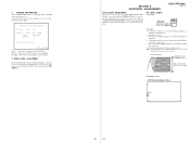
...(14 × 2 7/8 × 13 1/4 inches) (w/h/d) incl. HCD-C770/C990 Super Audio CD/DVD system Laser Semiconductor laser (Super Audio CD/DVD: λ = 650 nm) (CD: λ = 780 nm) Emission duration: continuous Signal format system NTSC or NTSC/PAL Frequency response (at 2 CH STEREO mode) DVD... system has performed the selfdiagnosis function. , Contact your nearest Sony dealer or local authorized Sony service facility and give the 5-character service number. C:13:00 First three characters of a letter and digits appears on the screen and the front panel display. projecting parts ...
...(14 × 2 7/8 × 13 1/4 inches) (w/h/d) incl. HCD-C770/C990 Super Audio CD/DVD system Laser Semiconductor laser (Super Audio CD/DVD: λ = 650 nm) (CD: λ = 780 nm) Emission duration: continuous Signal format system NTSC or NTSC/PAL Frequency response (at 2 CH STEREO mode) DVD... system has performed the selfdiagnosis function. , Contact your nearest Sony dealer or local authorized Sony service facility and give the 5-character service number. C:13:00 First three characters of a letter and digits appears on the screen and the front panel display. projecting parts ...

Service Manual
Page 3
...bottom exterior. A commercial leakage tester, such as described below. REPLACE THESE COMPONENTS WITH SONY PARTS WHOSE PART NUMBERS APPEAR AS SHOWN IN THIS MANUAL OR IN SUPPLEMENTS PUBLISHED BY SONY. aged by means of a tantalum capacitor may result in hazardous radiation exposure. Leakage ...a VOM or battery-operated AC voltmeter. Nearly all exposed metal parts to chassis, must have a 2 V AC range are suitable. (See Fig. Earth Ground Fig. A. HCD-C770/C990 Notes on the bottom exterior. A) To Exposed Metal Parts on Set 0.15 µF 1.5 kΩ AC voltmeter (0.75...
...bottom exterior. A commercial leakage tester, such as described below. REPLACE THESE COMPONENTS WITH SONY PARTS WHOSE PART NUMBERS APPEAR AS SHOWN IN THIS MANUAL OR IN SUPPLEMENTS PUBLISHED BY SONY. aged by means of a tantalum capacitor may result in hazardous radiation exposure. Leakage ...a VOM or battery-operated AC voltmeter. Nearly all exposed metal parts to chassis, must have a 2 V AC range are suitable. (See Fig. Earth Ground Fig. A. HCD-C770/C990 Notes on the bottom exterior. A) To Exposed Metal Parts on Set 0.15 µF 1.5 kΩ AC voltmeter (0.75...

Service Manual
Page 4
...) ........ 116 8-11. AUDIO Board, VIDEO Board 11 3-6. Timing Belt... Block Diagram - AUDIO (DSP) Section 33 7-3. VIDEO Section 35 7-5. ... 7-25. AUDIO Section 59 7-29. HCD-C770/C990 Ver 1.5 ...VIDEO Section 61 7-31. DC-DC CONVERTER Section 63 7-33. POWER Section (1/2) - ....... 68 7-38. Front Panel Section-1 108 8-3. Optical Pick-up (DVBU16 13 3-10. RELAY Board 15 3-13. Block Diagram - AUDIO... 21 4-6. TEST MODE 24 6. VIDEO Section 60 7-30. Schematic Diagram ...AUDIO Section 58 7-28. CONTROL Section 65 7-35. IC Pin Function Description 88 ...
...) ........ 116 8-11. AUDIO Board, VIDEO Board 11 3-6. Timing Belt... Block Diagram - AUDIO (DSP) Section 33 7-3. VIDEO Section 35 7-5. ... 7-25. AUDIO Section 59 7-29. HCD-C770/C990 Ver 1.5 ...VIDEO Section 61 7-31. DC-DC CONVERTER Section 63 7-33. POWER Section (1/2) - ....... 68 7-38. Front Panel Section-1 108 8-3. Optical Pick-up (DVBU16 13 3-10. RELAY Board 15 3-13. Block Diagram - AUDIO... 21 4-6. TEST MODE 24 6. VIDEO Section 60 7-30. Schematic Diagram ...AUDIO Section 58 7-28. CONTROL Section 65 7-35. IC Pin Function Description 88 ...

Service Manual
Page 5
...of the remote commander, and set , etc., connect the extension cable as to electrostatic break-down because of an demonstration disc in the repair parts. Releasing Procedure: 1. Therefore, when checking the laser diode emission, observe from more than 30 cm away from the objective lens. Procedure: ...1. J-2501-217-A) extension cable (DVD board-AMP board) (Part No. SECTION 1 SERVICING NOTES HCD-C770/C990 Ver 1.6 NOTES ON HANDLING THE OPTICAL PICK-UP BLOCK OR BASE UNIT The laser diode in the optical pick-up block....
...of the remote commander, and set , etc., connect the extension cable as to electrostatic break-down because of an demonstration disc in the repair parts. Releasing Procedure: 1. Therefore, when checking the laser diode emission, observe from more than 30 cm away from the objective lens. Procedure: ...1. J-2501-217-A) extension cable (DVD board-AMP board) (Part No. SECTION 1 SERVICING NOTES HCD-C770/C990 Ver 1.6 NOTES ON HANDLING THE OPTICAL PICK-UP BLOCK OR BASE UNIT The laser diode in the optical pick-up block....

Service Manual
Page 24
... use exiting test disc for the DVD system processor (IC206) is displayed. Syscon Diagnosis...is suspended and error is stored. (4 digits hexadecimal number) 24 Video 7. Normally, all diagnostic items continuously. PREV] button to the Test...of each item. Check Items List: 0-2. EEPROM Check 0-3-1. Version 0-2-2. HCD-C770/C990 Ver 1.4 SECTION 5 TEST MODE [GENERAL DESCRIPTION] The Test Mode allows... [STARTING TEST MODE] 1. Mecha Aging 4. Model Type 0-2-5. Audio Check 0-2. TDV-520CSO (DVD-SL): PART No. Audio Check Menu 0-0. All (All items continuous check) This menu ...
... use exiting test disc for the DVD system processor (IC206) is displayed. Syscon Diagnosis...is suspended and error is stored. (4 digits hexadecimal number) 24 Video 7. Normally, all diagnostic items continuously. PREV] button to the Test...of each item. Check Items List: 0-2. EEPROM Check 0-3-1. Version 0-2-2. HCD-C770/C990 Ver 1.4 SECTION 5 TEST MODE [GENERAL DESCRIPTION] The Test Mode allows... [STARTING TEST MODE] 1. Mecha Aging 4. Model Type 0-2-5. Audio Check 0-2. TDV-520CSO (DVD-SL): PART No. Audio Check Menu 0-0. All (All items continuous check) This menu ...
Service Manual
Page 31
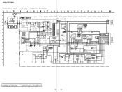
...31 31 Front End : The version of DVD system processor (IC206). RF LEVEL CHECK Connection: DVD board CN301 1 pin CN301 3 pin HCD-C770/C990 Ver 1.6 oscilloscope + - Perform confirmation in ...version field is clear and check RF sig- Ver.x. SYScon. : The version of mechanism controller (IC301). 7. VIDEO LEVEL ADJUSTMENT On the Test Mode Menu screen, selecting [7] displays color bars for video... ## Version Information ## IF con. Put the disc (LUV-P01) (Part No.: 4-999-032-01) (CD) in TEST MODE) and adjust...
...31 31 Front End : The version of DVD system processor (IC206). RF LEVEL CHECK Connection: DVD board CN301 1 pin CN301 3 pin HCD-C770/C990 Ver 1.6 oscilloscope + - Perform confirmation in ...version field is clear and check RF sig- Ver.x. SYScon. : The version of mechanism controller (IC301). 7. VIDEO LEVEL ADJUSTMENT On the Test Mode Menu screen, selecting [7] displays color bars for video... ## Version Information ## IF con. Put the disc (LUV-P01) (Part No.: 4-999-032-01) (CD) in TEST MODE) and adjust...

Service Manual
Page 37
... pattern face side seen from the parts face are indicated. pF: µµF 50 WV or less are not indicated except for safety. J : CD PLAY c : DVD PLAY I : SACD PLAY f : AUX IN i : OPTICAL DEITAL IN d : TUNER F : AUDIO L : VIDEO E :Y a : CHROMA r : COMPONENT VIDEO • Abbreviation AUS : Australian model CND : Canadian model HCD-C770/C990 • Circuit Boards Location DDCON...
... pattern face side seen from the parts face are indicated. pF: µµF 50 WV or less are not indicated except for safety. J : CD PLAY c : DVD PLAY I : SACD PLAY f : AUX IN i : OPTICAL DEITAL IN d : TUNER F : AUDIO L : VIDEO E :Y a : CHROMA r : COMPONENT VIDEO • Abbreviation AUS : Australian model CND : Canadian model HCD-C770/C990 • Circuit Boards Location DDCON...
Service Manual
Page 70
... NC 6.5V DVD3.3V E5.6V RESET P.CONT1 P.CONT2 A/D MGND DGND DGND AGND P.CONT3 (Page 53) The components identified by mark 0 or dotted line with part number specified. HCD-C770/C990 7-39.
... NC 6.5V DVD3.3V E5.6V RESET P.CONT1 P.CONT2 A/D MGND DGND DGND AGND P.CONT3 (Page 53) The components identified by mark 0 or dotted line with part number specified. HCD-C770/C990 7-39.
Service Manual
Page 107
... required for safety. Some delay should be anticipated when ordering these items. • Abbreviation AUS : Australian model CND : Canadian model HCD-C770/C990 The components identified by mark 0 or dotted line with part number specified. Les composants identifiés par une marque 0 sont critiquens pour la sécurité. Ne les remplacer que...
... required for safety. Some delay should be anticipated when ordering these items. • Abbreviation AUS : Australian model CND : Canadian model HCD-C770/C990 The components identified by mark 0 or dotted line with part number specified. Les composants identifiés par une marque 0 sont critiquens pour la sécurité. Ne les remplacer que...

Service Manual
Page 108
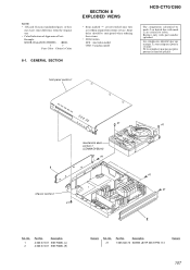
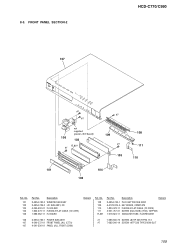
No. 56 57 58 58 #1 Part No. Description 2-626-294-01 SCREW (+ PTPWH) (2.6X7) 1-685-083-11 HP BOARD 4-240-024-01 KNOB VOLUME (C770) X-4952-564-1 KNOB (VOL) ASSY (C990) 7-685-646-79 SCREW +BVTP 3X8 TYPE2 IT-3 Remark 108 No. 51 52 53 54 55 Part No. Description 4-240-382-01 CD BUTTON 4-240-383-01 BAND BUTTON 1-685-068-11 CONTROL BOARD A-4676-963-A DDCON BOARD, COMPLETE 1-685-084-11 VOL BOARD Remark Ref. HCD-C770/C990 8-2. FRONT PANEL SECTION-1 front panel section-2 #1 not supplied #1 53 54 #1 55 56 57 51 52 58 not supplied supplied with S800 Ref.
No. 56 57 58 58 #1 Part No. Description 2-626-294-01 SCREW (+ PTPWH) (2.6X7) 1-685-083-11 HP BOARD 4-240-024-01 KNOB VOLUME (C770) X-4952-564-1 KNOB (VOL) ASSY (C990) 7-685-646-79 SCREW +BVTP 3X8 TYPE2 IT-3 Remark 108 No. 51 52 53 54 55 Part No. Description 4-240-382-01 CD BUTTON 4-240-383-01 BAND BUTTON 1-685-068-11 CONTROL BOARD A-4676-963-A DDCON BOARD, COMPLETE 1-685-084-11 VOL BOARD Remark Ref. HCD-C770/C990 8-2. FRONT PANEL SECTION-1 front panel section-2 #1 not supplied #1 53 54 #1 55 56 57 51 52 58 not supplied supplied with S800 Ref.
Service Manual
Page 109
No. 101 102 103 104 105 Part No. Description X-4954-740-3 WINDOW SUB ASSY X-4954-729-2 LID SUB ASSY, CD 4-240-402-01 FL HOLDER 1-824-479-11 FLEXIBLE FLAT CABLE (10 ...-11 INDICATOR TUBE, FLUORESCENT 106 X-4954-736-1 POWER SUB ASSY 107 4-240-372-01 FRONT PANEL (AL) (C770) 107 4-241-536-01 PANEL (AL), FRONT (C990) #1 7-685-646-79 SCREW +BVTP 3X8 TYPE2 IT-3 #7 7-685-246-14 SCREW +KTP 3X8 TYPE2 NON-SLIT 109 No. 108 109 110 111 FL801...
No. 101 102 103 104 105 Part No. Description X-4954-740-3 WINDOW SUB ASSY X-4954-729-2 LID SUB ASSY, CD 4-240-402-01 FL HOLDER 1-824-479-11 FLEXIBLE FLAT CABLE (10 ...-11 INDICATOR TUBE, FLUORESCENT 106 X-4954-736-1 POWER SUB ASSY 107 4-240-372-01 FRONT PANEL (AL) (C770) 107 4-241-536-01 PANEL (AL), FRONT (C990) #1 7-685-646-79 SCREW +BVTP 3X8 TYPE2 IT-3 #7 7-685-246-14 SCREW +KTP 3X8 TYPE2 NON-SLIT 109 No. 108 109 110 111 FL801...

Service Manual
Page 110
No. #1 #2 Part No. CHASSIS SECTION-1 not supplied #2 152 not supplied (power SW board) #1 not supplied (SEL board) #1 not supplied #1 chassis section-2 151 #1 153 Ref. HCD-C770/C990 8-4. No. 151 152 153 Part No. Description X-4954-745-1 FOOT SUB ASSY 4-240-397-01 POWER BUTTON 4-240-410-01 FOOT 110 Remark Ref. Description 7-685-646-79 SCREW +BVTP 3X8 TYPE2 IT-3 7-685-545-14 SCREW +BTP 3X6 TYPE2 N-S Remark
No. #1 #2 Part No. CHASSIS SECTION-1 not supplied #2 152 not supplied (power SW board) #1 not supplied (SEL board) #1 not supplied #1 chassis section-2 151 #1 153 Ref. HCD-C770/C990 8-4. No. 151 152 153 Part No. Description X-4954-745-1 FOOT SUB ASSY 4-240-397-01 POWER BUTTON 4-240-410-01 FOOT 110 Remark Ref. Description 7-685-646-79 SCREW +BVTP 3X8 TYPE2 IT-3 7-685-545-14 SCREW +BTP 3X6 TYPE2 N-S Remark
Service Manual
Page 111
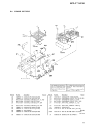
Ref. CHASSIS SECTION-2 HCD-C770/C990 #1 #1 #1 not supplied F901 #1 202 201 not supplied 205 204 203 #1 not supplied 207 chassis section-3 208 #1 212 206 209 #1 211 210 The components identified by mark 0 or dotted line with part number specified. Description Remark 1-824-626-11 FLEXIBLE FLAT CABLE... (19 CORE) 1-824-483-11 FLEXIBLE FLAT CABLE (28 CORE) A-4676-951-A DVD BOARD, COMPLETE (C770: US, CND) A-4729-049-A DVD BOARD, COMPLETE (C990) A-4730-636-A DVD BOARD, ...
Ref. CHASSIS SECTION-2 HCD-C770/C990 #1 #1 #1 not supplied F901 #1 202 201 not supplied 205 204 203 #1 not supplied 207 chassis section-3 208 #1 212 206 209 #1 211 210 The components identified by mark 0 or dotted line with part number specified. Description Remark 1-824-626-11 FLEXIBLE FLAT CABLE... (19 CORE) 1-824-483-11 FLEXIBLE FLAT CABLE (28 CORE) A-4676-951-A DVD BOARD, COMPLETE (C770: US, CND) A-4729-049-A DVD BOARD, COMPLETE (C990) A-4730-636-A DVD BOARD, ...
Service Manual
Page 112
... HCD-C770/C990 8-6. Ne les remplacer que par une pièce portant le numéro spécifié. Les composants identifiés par une marque 0 sont critiques pour la sécurité. No. 251 252 0 253 0 253 0 253 254 255 255 256 Part No. Description A-4728-874-A VIDEO ...BOARD, COMPLETE 1-824-485-11 FLEXIBLE FLAT CABLE (11 CORE) 1-783-531-72 CORD, POWER (US, CND) 1-696-169-12 CORD, POWER (AEP) 1-696-848-42 CORD, POWER (AUS) Remark 4-217-350-11 STOPPER, CORD A-4728-875-A AUDIO BOARD, COMPLETE (EXCEPT AEP) A-4730-641-A AUDIO BOARD, COMPLETE (AEP...
... HCD-C770/C990 8-6. Ne les remplacer que par une pièce portant le numéro spécifié. Les composants identifiés par une marque 0 sont critiques pour la sécurité. No. 251 252 0 253 0 253 0 253 254 255 255 256 Part No. Description A-4728-874-A VIDEO ...BOARD, COMPLETE 1-824-485-11 FLEXIBLE FLAT CABLE (11 CORE) 1-783-531-72 CORD, POWER (US, CND) 1-696-169-12 CORD, POWER (AEP) 1-696-848-42 CORD, POWER (AUS) Remark 4-217-350-11 STOPPER, CORD A-4728-875-A AUDIO BOARD, COMPLETE (EXCEPT AEP) A-4730-641-A AUDIO BOARD, COMPLETE (AEP...

Service Manual
Page 113
MECHANISM DECK SECTION-1 (CDM69-DVBU16) HCD-C770/C990 305 302 #4 303 301 304 S702 #4 306 M781 308 309 mechanism deck section-2 310 302 307 #4 Ref. Description Remark 1-685-006-11 STOCKER MOTOR BOARD 4-... CAM (STOCKER U/D) 4-239-618-01 SCREW (+PWH, 2X6), STEP TAPPING X-4954-628-1 STOCKER ASSY Ref. 8-7. No. 301 302 303 304 305 Part No. No. 308 309 310 M781 S702 Part No. Description Remark 4-239-689-01 GEAR (STOCKER DECELERATION) 4-239-698-01 PULLEY (STOCKER) 4-240-035-01 BELT (STOCKER) A-4735-953-A MOTOR...
MECHANISM DECK SECTION-1 (CDM69-DVBU16) HCD-C770/C990 305 302 #4 303 301 304 S702 #4 306 M781 308 309 mechanism deck section-2 310 302 307 #4 Ref. Description Remark 1-685-006-11 STOCKER MOTOR BOARD 4-... CAM (STOCKER U/D) 4-239-618-01 SCREW (+PWH, 2X6), STEP TAPPING X-4954-628-1 STOCKER ASSY Ref. 8-7. No. 301 302 303 304 305 Part No. No. 308 309 310 M781 S702 Part No. Description Remark 4-239-689-01 GEAR (STOCKER DECELERATION) 4-239-698-01 PULLEY (STOCKER) 4-240-035-01 BELT (STOCKER) A-4735-953-A MOTOR...
Service Manual
Page 114
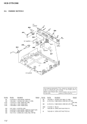
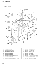
No. 355 356 #5 Part No. HCD-C770/C990 8-8. Description Remark 4-951-620-01 SCREW (2.6X8), +BVTP 4-985-672-01 SCREW (+PTPWHM 2.6), FLOATING 7-685-533-14 SCREW +BTP 2.6X6 TYPE2 N-S Description 1-685-008-11 SW BOARD (1) 1-685-009-11 SW BOARD (2) 1-685-010-11 SW BOARD (3) 1-685-011-11 SW BOARD (4) 114 Remark Ref. MECHANISM DECK SECTION-2 (CDM69-DVBU16) 352 353 #5 354 355 351 355 mechanism deck section-3 optical pick-up (DVBU16) mechanism deck section-4 356 Ref. No. 351 352 353 354 Part No.
No. 355 356 #5 Part No. HCD-C770/C990 8-8. Description Remark 4-951-620-01 SCREW (2.6X8), +BVTP 4-985-672-01 SCREW (+PTPWHM 2.6), FLOATING 7-685-533-14 SCREW +BTP 2.6X6 TYPE2 N-S Description 1-685-008-11 SW BOARD (1) 1-685-009-11 SW BOARD (2) 1-685-010-11 SW BOARD (3) 1-685-011-11 SW BOARD (4) 114 Remark Ref. MECHANISM DECK SECTION-2 (CDM69-DVBU16) 352 353 #5 354 355 351 355 mechanism deck section-3 optical pick-up (DVBU16) mechanism deck section-4 356 Ref. No. 351 352 353 354 Part No.
Service Manual
Page 115
No. 401 402 403 404 405 Part No. No. 411 412 413 414 415 Part No. HCD-C770/C990 8-9. MECHANISM DECK SECTION-3 (CDM69-DVBU16) not supplied not supplied 406 407 not supplied 405 not supplied 413 420 405 not supplied 405 408 415 413 ...
No. 401 402 403 404 405 Part No. No. 411 412 413 414 415 Part No. HCD-C770/C990 8-9. MECHANISM DECK SECTION-3 (CDM69-DVBU16) not supplied not supplied 406 407 not supplied 405 not supplied 413 420 405 not supplied 405 408 415 413 ...
Service Manual
Page 116
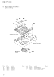
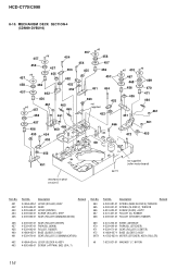
... 464 461 461 455 452 451 mechanism deck section-5 M771 not supplied (roller motor board) Ref. No. 464 465 466 467 468 Part No. No. 451 452 453 454 455 Part No. Description Remark 4-240-981-01 SPRING (BASE SLIDER 5),TENSION 4-240-041-01 SPRING (SLIDER 2), TENSION 4-951-620-01 SCREW (2.6X8...-953-A MOTOR (STOCKER) ASSY (ROLLER) 462 X-4954-624-A LEVER (SLIDER 4) ASSY 463 4-992-069-01 SCREW (+PTPWH) (M2) (DIA. 7) #6 7-623-921-01 WASHER 1.7, NYRON 116 HCD-C770/C990 8-10.
... 464 461 461 455 452 451 mechanism deck section-5 M771 not supplied (roller motor board) Ref. No. 464 465 466 467 468 Part No. No. 451 452 453 454 455 Part No. Description Remark 4-240-981-01 SPRING (BASE SLIDER 5),TENSION 4-240-041-01 SPRING (SLIDER 2), TENSION 4-951-620-01 SCREW (2.6X8...-953-A MOTOR (STOCKER) ASSY (ROLLER) 462 X-4954-624-A LEVER (SLIDER 4) ASSY 463 4-992-069-01 SCREW (+PTPWH) (M2) (DIA. 7) #6 7-623-921-01 WASHER 1.7, NYRON 116 HCD-C770/C990 8-10.
Service Manual
Page 117
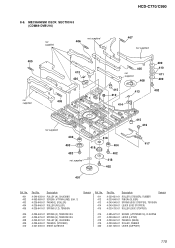
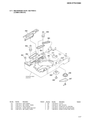
8-11. No. 501 502 503 504 505 Part No. Description 4-240-020-01 GEAR (TIMING) 4-239-708-01 BELT (FRONT), TIMING 4-239-697-01 GEAR (CENTER) X-4954-629-1 SLIDER (MODE CAM) ASSY 4-239-706-01 BELT (REAR), TIMING Remark Ref. Description 4-239-699-01 PULLEY 4-239-681-01 BELT (ROLLER) 4-227-899-01 SCREW (DIA. 12), FROATING 4-239-686-01 GEAR (ROLLER DECELERATION) 7-685-902-21 SCREW +PTPWH 2.6X8 (TYPE2) Remark 117 MECHANISM DECK SECTION-5 (CDM69-DVBU16) HCD-C770/C990 504 503 502 501 503 505 505 mechanism deck section-6 509 508 506 507 #4 Ref. No. 506 507 508 509 #4 Part No.
8-11. No. 501 502 503 504 505 Part No. Description 4-240-020-01 GEAR (TIMING) 4-239-708-01 BELT (FRONT), TIMING 4-239-697-01 GEAR (CENTER) X-4954-629-1 SLIDER (MODE CAM) ASSY 4-239-706-01 BELT (REAR), TIMING Remark Ref. Description 4-239-699-01 PULLEY 4-239-681-01 BELT (ROLLER) 4-227-899-01 SCREW (DIA. 12), FROATING 4-239-686-01 GEAR (ROLLER DECELERATION) 7-685-902-21 SCREW +PTPWH 2.6X8 (TYPE2) Remark 117 MECHANISM DECK SECTION-5 (CDM69-DVBU16) HCD-C770/C990 504 503 502 501 503 505 505 mechanism deck section-6 509 508 506 507 #4 Ref. No. 506 507 508 509 #4 Part No.
Service Manual
Page 118
... GEAR (EJECT LOCK) 4-239-695-02 CAM (EJECT LOCK) 4-240-018-01 GEAR (MODE 4) Remark Ref. No. 551 552 553 554 555 Part No. No. 563 564 565 566 567 Part No. MECHANISM DECK SECTION-6 (CDM69-DVBU16) 563 565 551 #4 #4 554 M761 not supplied (mode motor board) not supplied #4 553 569 568...
... GEAR (EJECT LOCK) 4-239-695-02 CAM (EJECT LOCK) 4-240-018-01 GEAR (MODE 4) Remark Ref. No. 551 552 553 554 555 Part No. No. 563 564 565 566 567 Part No. MECHANISM DECK SECTION-6 (CDM69-DVBU16) 563 565 551 #4 #4 554 M761 not supplied (mode motor board) not supplied #4 553 569 568...


