
Operating Instructions
Page 3
... Precautions 5 (GB) Location and Function of Parts and Controls ....... 7 (GB) Front / Rear / Side 7 (GB) Indicator Section 8 (GB) Control Button Section (Top 8 (GB) Connector Panel 9 (GB) Remote Commander RM-980 11 (GB) Caution 13 (GB) Connections 14 (GB) Connecting the Speakers 14 (GB) Connecting the AC Power Cord 14 (GB) Cable management...
... Precautions 5 (GB) Location and Function of Parts and Controls ....... 7 (GB) Front / Rear / Side 7 (GB) Indicator Section 8 (GB) Control Button Section (Top 8 (GB) Connector Panel 9 (GB) Remote Commander RM-980 11 (GB) Caution 13 (GB) Connections 14 (GB) Connecting the Speakers 14 (GB) Connecting the AC Power Cord 14 (GB) Cable management...
Operating Instructions
Page 4
...) .... 39 (GB) Setting an IP address manually (Manual 40 (GB) Setting a communication speed 41 (GB) Self-diagnosis Function 41 (GB) Operating a Specific Display With the Remote Commander 42 (GB) Specifications 43 (GB) 4 (GB)
...) .... 39 (GB) Setting an IP address manually (Manual 40 (GB) Setting a communication speed 41 (GB) Self-diagnosis Function 41 (GB) Operating a Specific Display With the Remote Commander 42 (GB) Specifications 43 (GB) 4 (GB)
Operating Instructions
Page 5
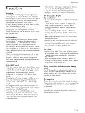
On installation • Allow adequate air circulation to prevent internal heat build-up during use. Take this unit, contact your authorized Sony dealers. 5 (GB) These do not indicate a malfunction. Precautions • If you install multiple equipment with the unit, the following problems, ... an ideal container in a colder environment. When shipping the unit, repack it is not to be sure to normal operation as malfunction of the Remote Commander, noisy picture, noisy sound, may block the ventilation holes. • Do not install the unit in a location near materials (curtains, ...
On installation • Allow adequate air circulation to prevent internal heat build-up during use. Take this unit, contact your authorized Sony dealers. 5 (GB) These do not indicate a malfunction. Precautions • If you install multiple equipment with the unit, the following problems, ... an ideal container in a colder environment. When shipping the unit, repack it is not to be sure to normal operation as malfunction of the Remote Commander, noisy picture, noisy sound, may block the ventilation holes. • Do not install the unit in a location near materials (curtains, ...
Operating Instructions
Page 8
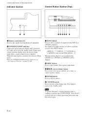
Location and Function of these operations before pressing this switch again. 8 (GB) INPUT1 INPUT2 OPTION1 OPTION2 (only for the FWD-40LX1) When an option adaptor is switched, the indicator blinks green. Press again to return to be input switches as follows each... show menus. Wait about 5 seconds after one of Parts and Controls Indicator Section Control Button Section (Top) 12 12345 6 1 Remote control detector Receives the signals from the Remote Commander. 2 POWER/STANDBY indicator Lights up in the OPTION slot, OPTION1 or OPTION2 will be input from a computer. Note To ...
Location and Function of these operations before pressing this switch again. 8 (GB) INPUT1 INPUT2 OPTION1 OPTION2 (only for the FWD-40LX1) When an option adaptor is switched, the indicator blinks green. Press again to return to be input switches as follows each... show menus. Wait about 5 seconds after one of Parts and Controls Indicator Section Control Button Section (Top) 12 12345 6 1 Remote control detector Receives the signals from the Remote Commander. 2 POWER/STANDBY indicator Lights up in the OPTION slot, OPTION1 or OPTION2 will be input from a computer. Note To ...
Operating Instructions
Page 9
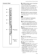
...IN CONTROL S OUT REMOTE Connector Panel 1 2 3 4 5 DVI-HDCP INPUT 1 AUDIO RGB/COMPONENT INPUT 2 AUDIO L AUDIO OUT R S VIDEO IN OUT VIDEO IN 6 7 OPTION1 Slot (VIDEO/COM ) VIDEO INPUT ADAPTOR OUT AUDIO IN L R 8 OPTION2 Slot (VIDEO) (Only for the FWD-40LX1) Location and ...-232C) connector (D-sub 9-pin) This connector allows remote control of video equipment. AUDIO (Stereo minijack) : Inputs an audio signal. AUDIO IN L/R (Pinjack) : Inputs an audio signal. For details, contact your authorized Sony dealers. Outputs an audio signal corresponding to the Active Picture...
...IN CONTROL S OUT REMOTE Connector Panel 1 2 3 4 5 DVI-HDCP INPUT 1 AUDIO RGB/COMPONENT INPUT 2 AUDIO L AUDIO OUT R S VIDEO IN OUT VIDEO IN 6 7 OPTION1 Slot (VIDEO/COM ) VIDEO INPUT ADAPTOR OUT AUDIO IN L R 8 OPTION2 Slot (VIDEO) (Only for the FWD-40LX1) Location and ...-232C) connector (D-sub 9-pin) This connector allows remote control of video equipment. AUDIO (Stereo minijack) : Inputs an audio signal. AUDIO IN L/R (Pinjack) : Inputs an audio signal. For details, contact your authorized Sony dealers. Outputs an audio signal corresponding to the Active Picture...
Operating Instructions
Page 11
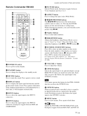
... and COMPONENT. Press again to restore sound. 4 DISPLAY button Press to change the display to the standby mode. 3 MUTING button Press to the INPUT2 connectors. Remote Commander RM-980 1 2 MUTING DISPLAY STBY ON 3 4 5 qf 6 qg 7 qh 8 qj 9 ENTER 123 0 456 789 qa 0 qk qs ON SET qd ql MONITOR RM-980...
... and COMPONENT. Press again to restore sound. 4 DISPLAY button Press to change the display to the standby mode. 3 MUTING button Press to the INPUT2 connectors. Remote Commander RM-980 1 2 MUTING DISPLAY STBY ON 3 4 5 qf 6 qg 7 qh 8 qj 9 ENTER 123 0 456 789 qa 0 qk qs ON SET qd ql MONITOR RM-980...
Operating Instructions
Page 12
Press this button and adjust the chroma with the M/m or Location and Function of Parts and Controls qk CHROMA button Adjusts the chroma when the picture mode is set to any of "User1" to "User3."
Press this button and adjust the chroma with the M/m or Location and Function of Parts and Controls qk CHROMA button Adjusts the chroma when the picture mode is set to any of "User1" to "User3."
Operating Instructions
Page 16
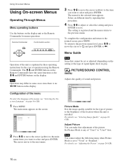
Using On-screen Menus Using On-screen Menus Operating Through Menus Menu operating buttons Use the buttons on the display. Note Operation may differ in some cases since there is explained in these operating instructions for menu operations. The M/m and ENTER buttons on the Remote Commander have the same functions as the M/m and ENTER buttons on the display unit or the Remote Commander for the case of operation using the Remote Commander. Remote Commander MENU Control button section ENTER Operation of the unit is no
Using On-screen Menus Using On-screen Menus Operating Through Menus Menu operating buttons Use the buttons on the display. Note Operation may differ in some cases since there is explained in these operating instructions for menu operations. The M/m and ENTER buttons on the Remote Commander have the same functions as the M/m and ENTER buttons on the display unit or the Remote Commander for the case of operation using the Remote Commander. Remote Commander MENU Control button section ENTER Operation of the unit is no
Operating Instructions
Page 18
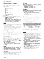
... the unit or switch the input signal. CUSTOM SETUP Power Saving: Speaker Out: Closed Caption: Display: Color Matrix HD Mode: RGB Mode Sync Mode: Illumination: Remote Standard Off Off Off 1080i H/Comp High Select Set ENTER Exit MENU Power Saving Reduces power consumption while showing pictures. However, note that you turn...
... the unit or switch the input signal. CUSTOM SETUP Power Saving: Speaker Out: Closed Caption: Display: Color Matrix HD Mode: RGB Mode Sync Mode: Illumination: Remote Standard Off Off Off 1080i H/Comp High Select Set ENTER Exit MENU Power Saving Reduces power consumption while showing pictures. However, note that you turn...
Operating Instructions
Page 19
...automatically enters the standby mode when a signal is not input to control it using . Color System Selects the Color System of the display. Remote Only: Disables the controls on page 36 (GB). While in the power saving mode, the display unit is automatically turned on the display ...for the display using ENTER on page 42 (GB). Illumination Switches the brightness of the "SONY" logo on the key you are using the Remote Commander only. Control Mode Selects the function of the Remote Commander. The display unit automatically enters the power saving mode when a signal is not ...
...automatically enters the standby mode when a signal is not input to control it using . Color System Selects the Color System of the display. Remote Only: Disables the controls on page 36 (GB). While in the power saving mode, the display unit is automatically turned on the display ...for the display using ENTER on page 42 (GB). Illumination Switches the brightness of the "SONY" logo on the key you are using the Remote Commander only. Control Mode Selects the function of the Remote Commander. The display unit automatically enters the power saving mode when a signal is not ...
Operating Instructions
Page 21
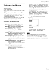
... the option 1 or 2 slot. For example, every time you press the corresponding button. Watching the Picture Press INPUT1, INPUT2, OPTION1 or OPTION2 button on the Remote Commander to the selected input connector, the indication changes every time you press the INPUT2 button, the indication switches to On. • To select the...
... the option 1 or 2 slot. For example, every time you press the corresponding button. Watching the Picture Press INPUT1, INPUT2, OPTION1 or OPTION2 button on the Remote Commander to the selected input connector, the indication changes every time you press the INPUT2 button, the indication switches to On. • To select the...
Operating Instructions
Page 22
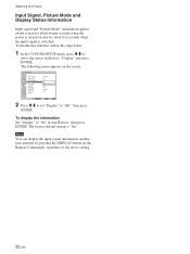
... following menu appears on the screen. Note You can display the input signal information and the time anytime by pressing the DISPLAY button on the Remote Commander, regardless of the above , then press ENTER. CUSTOM SETUP Power Saving: Speaker Out: Closed Caption: Display: Color Matrix: HD Mode: RGB... Mode: Sync Mode: Illumination: Remote Standard Off Off Off YO/nPB/PR 1080i DTV H/Comp High Select Set ENTER Exit MENU 2 Press M/m to set "Display" to "Display" and press ...
... following menu appears on the screen. Note You can display the input signal information and the time anytime by pressing the DISPLAY button on the Remote Commander, regardless of the above , then press ENTER. CUSTOM SETUP Power Saving: Speaker Out: Closed Caption: Display: Color Matrix: HD Mode: RGB... Mode: Sync Mode: Illumination: Remote Standard Off Off Off YO/nPB/PR 1080i DTV H/Comp High Select Set ENTER Exit MENU 2 Press M/m to set "Display" to "Display" and press ...
Operating Instructions
Page 32
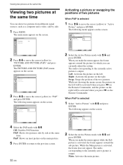
.... The following menu appears on the screen. Left: Activates the picture on the left will be activated when you press < on the Remote Commander, and the picture on the Remote Commander. Swap: Swaps the position of two pictures When P&P is activated, the frame appears around the picture for which you press , on...
.... The following menu appears on the screen. Left: Activates the picture on the left will be activated when you press < on the Remote Commander, and the picture on the Remote Commander. Swap: Swaps the position of two pictures When P&P is activated, the frame appears around the picture for which you press , on...
Operating Instructions
Page 33
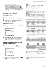
Zooming in on the Remote Commander. While not showing the menu screen, the main picture will be activated when you press < on the Remote Commander, and the inset picture will be activated when you press , on a picture When P&P is selected 1 Select "Picture Size" with M/m and press ENTER. 2 Keep pressing Swap: Swaps the main and the inset pictures. Sub: Activates the inset picture.
Zooming in on the Remote Commander. While not showing the menu screen, the main picture will be activated when you press < on the Remote Commander, and the inset picture will be activated when you press , on a picture When P&P is selected 1 Select "Picture Size" with M/m and press ENTER. 2 Keep pressing Swap: Swaps the main and the inset pictures. Sub: Activates the inset picture.
Operating Instructions
Page 36
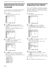
...menu appears on the screen. CUSTOM SETUP Power Saving: Speaker Out: Closed Caption: Display: Color Matrix: HD Mode: RGB Mode: Sync Mode: Illumination: Remote Standard Off Off Off Y/PCB/PCR 1Y0/P8B0i/PR DTV H/Comp High Select Set ENTER Exit MENU 4 Select the color matrix with a signal format (... menu appears on the screen. CUSTOM SETUP Power Saving: Speaker Out: Closed Caption: Display: Color Matrix: HD Mode: RGB Mode: Sync Mode: Illumination: Remote Standard Off Off Off Y/PB/PR 1080i DTV H/Comp High Select Set ENTER Exit MENU 3 Press M/m to move the cursor (yellow) to "Language" ...
...menu appears on the screen. CUSTOM SETUP Power Saving: Speaker Out: Closed Caption: Display: Color Matrix: HD Mode: RGB Mode: Sync Mode: Illumination: Remote Standard Off Off Off Y/PCB/PCR 1Y0/P8B0i/PR DTV H/Comp High Select Set ENTER Exit MENU 4 Select the color matrix with a signal format (... menu appears on the screen. CUSTOM SETUP Power Saving: Speaker Out: Closed Caption: Display: Color Matrix: HD Mode: RGB Mode: Sync Mode: Illumination: Remote Standard Off Off Off Y/PB/PR 1080i DTV H/Comp High Select Set ENTER Exit MENU 3 Press M/m to move the cursor (yellow) to "Language" ...

Operating Instructions
Page 37
... In the TIMER/CLOCK menu, press M/m to move the cursor (yellow) to "Clock Set" and press ENTER. The following menu appears on the Remote Commander, the signal currently input and the Picture Mode appear. "Clock Display : ON" will disappear automatically. If you hide the menu, the clock ... Press MENU. The following menu appears on the lower right corner of Week Select Set ENTER Exit MENU 37 (GB) Please contact your authorized Sony dealer to "On/Off Timer" and press ENTER. TIMER/CLOCK Clock Set Clock Display: Off On/Off Timer On Select Set ENTER Exit MENU...
... In the TIMER/CLOCK menu, press M/m to move the cursor (yellow) to "Clock Set" and press ENTER. The following menu appears on the Remote Commander, the signal currently input and the Picture Mode appear. "Clock Display : ON" will disappear automatically. If you hide the menu, the clock ... Press MENU. The following menu appears on the lower right corner of Week Select Set ENTER Exit MENU 37 (GB) Please contact your authorized Sony dealer to "On/Off Timer" and press ENTER. TIMER/CLOCK Clock Set Clock Display: Off On/Off Timer On Select Set ENTER Exit MENU...
Operating Instructions
Page 40
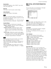
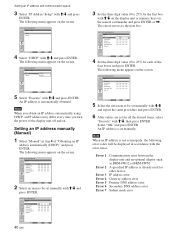
... used for the first box with M/m and repeat the same procedure and press ENTER. 6 After values are set properly, the following menu appears on the remote commander and press ENTER or ,. INITIAL SETUP/INFORMATION Manual IP Address: Subnet Mask: Gateway: Primay DNS: Secondary DNS: Execute 123 . 123 . 012 . 034 000 . 000...
... used for the first box with M/m and repeat the same procedure and press ENTER. 6 After values are set properly, the following menu appears on the remote commander and press ENTER or ,. INITIAL SETUP/INFORMATION Manual IP Address: Subnet Mask: Gateway: Primay DNS: Secondary DNS: Execute 123 . 123 . 012 . 034 000 . 000...

Operating Instructions
Page 42
...while the others change the index number You can operate the specified display indicated with M/m and press ENTER. The display returns to the Remote menu. You cannot change the index number if necessary. Input Number 123 456 789 0 ON SET OFF Index Number 117 117 3 ...Press ID MODE SET. Operating a Specific Display With the Remote Commander Operating a Specific Display With the Remote Commander Using the supplied Remote Commander, you can operate a specific display without affecting other displays, as well.) 42 (GB) Select Set ENTER ...
...while the others change the index number You can operate the specified display indicated with M/m and press ENTER. The display returns to the Remote menu. You cannot change the index number if necessary. Input Number 123 456 789 0 ON SET OFF Index Number 117 117 3 ...Press ID MODE SET. Operating a Specific Display With the Remote Commander Operating a Specific Display With the Remote Commander Using the supplied Remote Commander, you can operate a specific display without affecting other displays, as well.) 42 (GB) Select Set ENTER ...
Operating Instructions
Page 43
... AUDIO Stereo minijack (×1) 500 mVrms, high impedance CONTROL S IN/OUT Minijack (×2) AUDIO OUT Pinjack (×2) 500 mVrms, high impedance REMOTE (RS-232C) D-sub 9-pin (×1) SPEAKER 7 W + 7 W (6 ohms), direct unbalanced impedance: 6-16 ohms Specifications VIDEO/S VIDEO ...IN Pinjack (×2) 500 mVrms, high impedance General Power requirements 100 V to 240 V AC, 50/60 Hz, FWD-40LX1: 2.5 A to 1.2 A FWD-32LX1R: 1.7 A to 0.8 A Power consumption FWD-40LX1: 220 W FWD-32LX1R: 150 W Operating conditions Temperature: 0 °C to +35 °C (32 °F to 95 °F) Humidity...
... AUDIO Stereo minijack (×1) 500 mVrms, high impedance CONTROL S IN/OUT Minijack (×2) AUDIO OUT Pinjack (×2) 500 mVrms, high impedance REMOTE (RS-232C) D-sub 9-pin (×1) SPEAKER 7 W + 7 W (6 ohms), direct unbalanced impedance: 6-16 ohms Specifications VIDEO/S VIDEO ...IN Pinjack (×2) 500 mVrms, high impedance General Power requirements 100 V to 240 V AC, 50/60 Hz, FWD-40LX1: 2.5 A to 1.2 A FWD-32LX1R: 1.7 A to 0.8 A Power consumption FWD-40LX1: 220 W FWD-32LX1R: 150 W Operating conditions Temperature: 0 °C to +35 °C (32 °F to 95 °F) Humidity...
Operating Instructions
Page 44
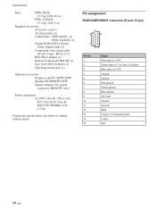
...ground Not used Ground Ground SDA H sync or Composite Video V sync SCL 44 (GB) RCA×3) (1) BNC-RCA adaptor (1) Remote Commander RM-980 (1) Size AAA (R03) batteries (2) Operating instructions (1) Optional accessories Display stand SU-42FW/32FW Speaker SS-SP40FW/32FW ... Design and specifications are subject to change without notice. Specifications Mass FWD-40LX1: 27.5 kg (60 lb 10 oz) FWD-32LX1R: 17.5 kg (38 lb 9 oz) Supplied accessories AC power cord (1) AC plug holder (2) Cable holder FWD-40LX1: (4) FWD-32LX1R: (6) Digital RGB (DVI-D) Signal Cable (Single Link) (1) ...
...ground Not used Ground Ground SDA H sync or Composite Video V sync SCL 44 (GB) RCA×3) (1) BNC-RCA adaptor (1) Remote Commander RM-980 (1) Size AAA (R03) batteries (2) Operating instructions (1) Optional accessories Display stand SU-42FW/32FW Speaker SS-SP40FW/32FW ... Design and specifications are subject to change without notice. Specifications Mass FWD-40LX1: 27.5 kg (60 lb 10 oz) FWD-32LX1R: 17.5 kg (38 lb 9 oz) Supplied accessories AC power cord (1) AC plug holder (2) Cable holder FWD-40LX1: (4) FWD-32LX1R: (6) Digital RGB (DVI-D) Signal Cable (Single Link) (1) ...


