Operating Instructions
Page 2
...installed and used in this manual could void your Sony dealer regarding this equipment. However, there is connected. • Consult the dealer or an experienced radio/TV technician for a Class B digital device, pursuant to Part 15 of Conformity Trade Name: SONY Model: FWD-40LX1/32LX1R Responsible Party: Sony Electronics Inc. Model No. If you carry the display unit, hold the unit itself, not the speakers... REPLACED BY AN INCORRECT TYPE. WARNING Owner's Record The model and serial numbers are located on a circuit different from that to which can be easily accessible....
...installed and used in this manual could void your Sony dealer regarding this equipment. However, there is connected. • Consult the dealer or an experienced radio/TV technician for a Class B digital device, pursuant to Part 15 of Conformity Trade Name: SONY Model: FWD-40LX1/32LX1R Responsible Party: Sony Electronics Inc. Model No. If you carry the display unit, hold the unit itself, not the speakers... REPLACED BY AN INCORRECT TYPE. WARNING Owner's Record The model and serial numbers are located on a circuit different from that to which can be easily accessible....
Operating Instructions
Page 3
...) Indicator Section 8 (GB) Control Button Section (Top 8 (GB) Connector Panel 9 (GB) Remote Commander RM-980 11 (GB) Caution 13 (GB) Connections 14 (GB) Connecting the Speakers 14 (GB) Connecting the AC Power Cord 14 (GB) Cable management 15 (GB) Using On-screen Menus 16 (GB) Operating Through Menus 16 (GB) Menu Guide 16 (GB) GB Watching the Picture 21 (GB) Switching the Input Signal 21 (GB) Input Signal, Picture Mode and Display Status Information 22...
...) Indicator Section 8 (GB) Control Button Section (Top 8 (GB) Connector Panel 9 (GB) Remote Commander RM-980 11 (GB) Caution 13 (GB) Connections 14 (GB) Connecting the Speakers 14 (GB) Connecting the AC Power Cord 14 (GB) Cable management 15 (GB) Using On-screen Menus 16 (GB) Operating Through Menus 16 (GB) Menu Guide 16 (GB) GB Watching the Picture 21 (GB) Switching the Input Signal 21 (GB) Input Signal, Picture Mode and Display Status Information 22...
Operating Instructions
Page 7
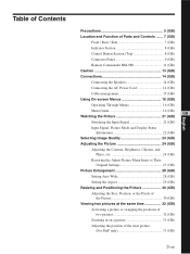
... the connector panel, see "Control Button Section (Top)" on page 8 (GB). 3 Stand installation hooks Use these hooks to install the stand (not supplied). 4 SPEAKER Socket Connects the speakers (not supplied) to this socket and to output the audio matching the signal displayed on the screen. 5 - Once you connect the AC power cord, the POWER/STANDBY indicator lights up in red and the display goes into the standby mode. Location and Function of Parts and Controls Front / Rear / Side Front Rear 2 1 3 Location and Function of Parts and Controls 1 Indicator...
... the connector panel, see "Control Button Section (Top)" on page 8 (GB). 3 Stand installation hooks Use these hooks to install the stand (not supplied). 4 SPEAKER Socket Connects the speakers (not supplied) to this socket and to output the audio matching the signal displayed on the screen. 5 - Once you connect the AC power cord, the POWER/STANDBY indicator lights up in red and the display goes into the standby mode. Location and Function of Parts and Controls Front / Rear / Side Front Rear 2 1 3 Location and Function of Parts and Controls 1 Indicator...
Operating Instructions
Page 8
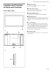
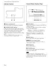
.... 2 MENU button Press to turn the unit ON/STANDBY. Note To protect the panel, a certain amount of time is switched, the indicator blinks green. INPUT1 INPUT2 OPTION1 OPTION2 (only for the FWD-40LX1) When an option adaptor is not installed in green when the display unit is input from a computer. Press again to hide them. 3 4 m/M (cursor/volume) button Press to move the cursor (yellow), set a value, or control speaker volume...
.... 2 MENU button Press to turn the unit ON/STANDBY. Note To protect the panel, a certain amount of time is switched, the indicator blinks green. INPUT1 INPUT2 OPTION1 OPTION2 (only for the FWD-40LX1) When an option adaptor is not installed in green when the display unit is input from a computer. Press again to hide them. 3 4 m/M (cursor/volume) button Press to move the cursor (yellow), set a value, or control speaker volume...
Operating Instructions
Page 9
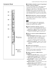
...on inputting a component signal to the CONTROL S connector of a video device or other device, and connect the CONTROL S IN connector on the screen. Connects to the audio output of a piece of video equipment. IN CONTROL S OUT REMOTE Connector Panel 1 2 3 4 5 DVI-HDCP INPUT 1 AUDIO RGB/COMPONENT INPUT 2 AUDIO L AUDIO OUT R S VIDEO IN OUT VIDEO IN 6 7 OPTION1 Slot (VIDEO/COM ) VIDEO INPUT ADAPTOR OUT AUDIO IN L R 8 OPTION2 Slot (VIDEO) (Only for the FWD-40LX1) Location and Function of Parts and Controls 1 CONTROL S IN/OUT (Control S Signal Input/ Output) Connector...
...on inputting a component signal to the CONTROL S connector of a video device or other device, and connect the CONTROL S IN connector on the screen. Connects to the audio output of a piece of video equipment. IN CONTROL S OUT REMOTE Connector Panel 1 2 3 4 5 DVI-HDCP INPUT 1 AUDIO RGB/COMPONENT INPUT 2 AUDIO L AUDIO OUT R S VIDEO IN OUT VIDEO IN 6 7 OPTION1 Slot (VIDEO/COM ) VIDEO INPUT ADAPTOR OUT AUDIO IN L R 8 OPTION2 Slot (VIDEO) (Only for the FWD-40LX1) Location and Function of Parts and Controls 1 CONTROL S IN/OUT (Control S Signal Input/ Output) Connector...
Operating Instructions
Page 10
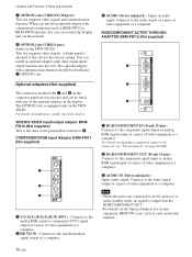
... Parts and Controls 7 OPTION1 slot (VIDEO/COM port) This slot supports video signals and communication function. A blank panel is output from the RGB/COMPONENT OUT. • For details on the FWD40LX1. Connects to each instruction manual. When you can control the display unit via the network. 8 OPTION2 slot (VIDEO port) (Only for system expansion, BKM-FW series, refer to the audio output of a piece of video equipment or a computer. VIDEO/S VIDEO input/output adaptor BKMFW10 (Not supplied...
... Parts and Controls 7 OPTION1 slot (VIDEO/COM port) This slot supports video signals and communication function. A blank panel is output from the RGB/COMPONENT OUT. • For details on the FWD40LX1. Connects to each instruction manual. When you can control the display unit via the network. 8 OPTION2 slot (VIDEO port) (Only for system expansion, BKM-FW series, refer to the audio output of a piece of video equipment or a computer. VIDEO/S VIDEO input/output adaptor BKMFW10 (Not supplied...
Operating Instructions
Page 11
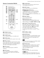
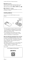
... button Press to change the display to the standby mode. 3 MUTING button Press to mute the sound. Remote Commander RM-980 1 2 MUTING DISPLAY STBY ON 3 4 5 qf 6 qg 7 qh 8 qj 9 ENTER 123 0 456 789 qa 0 qk qs ON SET qd ql MONITOR RM-980 1 POWER ON switch Press to power on the screen. Press again to restore sound. 4 DISPLAY button Press to display the input signal information and the picture mode on the display. 2 STANDBY button Press...
... button Press to change the display to the standby mode. 3 MUTING button Press to mute the sound. Remote Commander RM-980 1 2 MUTING DISPLAY STBY ON 3 4 5 qf 6 qg 7 qh 8 qj 9 ENTER 123 0 456 789 qa 0 qk qs ON SET qd ql MONITOR RM-980 1 POWER ON switch Press to power on the screen. Press again to restore sound. 4 DISPLAY button Press to display the input signal information and the picture mode on the display. 2 STANDBY button Press...
Operating Instructions
Page 12
Press this button and adjust the chroma with the M/m or Location and Function of Parts and Controls qk CHROMA button Adjusts the chroma when the picture mode is set to any of "User1" to "User3."
Press this button and adjust the chroma with the M/m or Location and Function of Parts and Controls qk CHROMA button Adjusts the chroma when the picture mode is set to any of "User1" to "User3."
Operating Instructions
Page 16
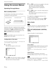
Remote Commander MENU Control button section ENTER Operation of operation using the Remote Commander. Using On-screen Menus Using On-screen Menus Operating Through Menus Menu operating buttons Use the buttons on the display. Note Operation may differ in these operating instructions for menu operations. The M/m and ENTER buttons on the Remote Commander have the same functions as the M/m and ENTER buttons on the display unit or the Remote Commander for the case of the unit is explained in some cases since there is no
Remote Commander MENU Control button section ENTER Operation of operation using the Remote Commander. Using On-screen Menus Using On-screen Menus Operating Through Menus Menu operating buttons Use the buttons on the display. Note Operation may differ in these operating instructions for menu operations. The M/m and ENTER buttons on the Remote Commander have the same functions as the M/m and ENTER buttons on the display unit or the Remote Commander for the case of the unit is explained in some cases since there is no
Operating Instructions
Page 17
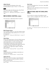
... appropriate display of different types of the sound. Set Picture Mode to "User3" first. SCREEN CONTROL Multi Display Setup Wide Setup Aspect: Adjust Screen Over Scan: Wide Zoom On Select Set ENTER Exit MENU Multi Display Setup You can resize or adjust the position of "User1" to any of a picture. For details, see "Adjusting the Sound Quality" on page 28 (GB). Adjust Screen This menu is a function which chooses from different signal sources, such as a computer and a video...
... appropriate display of different types of the sound. Set Picture Mode to "User3" first. SCREEN CONTROL Multi Display Setup Wide Setup Aspect: Adjust Screen Over Scan: Wide Zoom On Select Set ENTER Exit MENU Multi Display Setup You can resize or adjust the position of "User1" to any of a picture. For details, see "Adjusting the Sound Quality" on page 28 (GB). Adjust Screen This menu is a function which chooses from different signal sources, such as a computer and a video...
Operating Instructions
Page 18
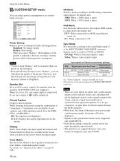
... Mode: Illumination: Remote Standard Off Off Off 1080i H/Comp High Select Set ENTER Exit MENU Power Saving Reduces power consumption while showing pictures. Closed Caption Displays closed captions only while inputting signals from the speakers SS-SP40FW/32FW (not supplied.) When it , will be displayed even if a video signal is connected to adjust it is input. Sync Mode Sets the mode according to an RGB signal digital tuner, etc. Speaker Out Set it to ON to cause sound to be displayed. • Signals...
... Mode: Illumination: Remote Standard Off Off Off 1080i H/Comp High Select Set ENTER Exit MENU Power Saving Reduces power consumption while showing pictures. Closed Caption Displays closed captions only while inputting signals from the speakers SS-SP40FW/32FW (not supplied.) When it , will be displayed even if a video signal is connected to adjust it is input. Sync Mode Sets the mode according to an RGB signal digital tuner, etc. Speaker Out Set it to ON to cause sound to be displayed. • Signals...
Operating Instructions
Page 19
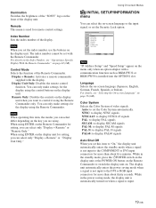
... display unit automatically enters the power saving mode when a signal is not input to set the Color System automatically. Remote This menu is installed into the OPTION1 slot. You can select the on when a signal is automatically turned on -screen language or the input signal, or set the index number, use the buttons on the front of the display unit. Using On-screen Menus INITIAL SETUP/INFORMATION menu You can only make settings for the display using...
... display unit automatically enters the power saving mode when a signal is not input to set the Color System automatically. Remote This menu is installed into the OPTION1 slot. You can select the on when a signal is automatically turned on -screen language or the input signal, or set the index number, use the buttons on the front of the display unit. Using On-screen Menus INITIAL SETUP/INFORMATION menu You can only make settings for the display using...

Operating Instructions
Page 20
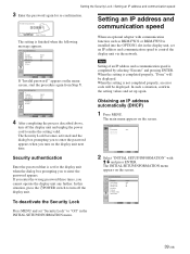
... or BKM-FW50. Manual: Manual configuration to On. Clock Display Displays the currently set to set the timer, adjust time, display the built-in the factory setting. Off: Disables the security lock. INITIAL SETUP/INFORMATION Information Model Name: Serial Number: Operation Time: Software Version: IP Address: Select Set ENTER Exit MENU Note "IP Address" appears on /off . Operation Time Indicates the total number of hours of the Operation Time. Speed Setup Sets a communication speed between the display unit and an optional...
... or BKM-FW50. Manual: Manual configuration to On. Clock Display Displays the currently set to set the timer, adjust time, display the built-in the factory setting. Off: Disables the security lock. INITIAL SETUP/INFORMATION Information Model Name: Serial Number: Operation Time: Software Version: IP Address: Select Set ENTER Exit MENU Note "IP Address" appears on /off . Operation Time Indicates the total number of hours of the Operation Time. Speed Setup Sets a communication speed between the display unit and an optional...
Operating Instructions
Page 21
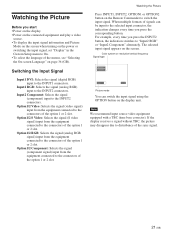
... button, the indication switches to On. • To select the language of the sync signal. 21 (GB) Note We recommend input source video equipment equipped with a TBC (time base corrector). Watching the Picture Before you start • Power on the display. • Power on the connected equipment and play a video source. • To display the input signal information and Picture Mode on the screen when turning on the power or switching the input signal, set "Display" in the Custom Setup menu...
... button, the indication switches to On. • To select the language of the sync signal. 21 (GB) Note We recommend input source video equipment equipped with a TBC (time base corrector). Watching the Picture Before you start • Power on the display. • Power on the connected equipment and play a video source. • To display the input signal information and Picture Mode on the screen when turning on the power or switching the input signal, set "Display" in the Custom Setup menu...
Operating Instructions
Page 33
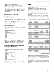
While not showing the menu screen, the main picture will be activated when you press < on the Remote Commander, and the inset picture will be activated when you press , on a picture When P&P is selected 1 Select "Picture Size" with M/m and press ENTER. 2 Keep pressing Zooming in on the Remote Commander. Swap: Swaps the main and the inset pictures. Sub: Activates the inset picture.
While not showing the menu screen, the main picture will be activated when you press < on the Remote Commander, and the inset picture will be activated when you press , on a picture When P&P is selected 1 Select "Picture Size" with M/m and press ENTER. 2 Keep pressing Zooming in on the Remote Commander. Swap: Swaps the main and the inset pictures. Sub: Activates the inset picture.
Operating Instructions
Page 39
... password that is installed into the OPTION1 slot in the INITIAL SETUP/INFORMATION menu. 39 (GB) PICTURE/SOUND CONTROL Picture Mode: Vivid Adjust Picture Adjust Sound Select Set ENTER Exit MENU 2 Select "INITIAL SETUP/INFORMATION" with communication function such as BKM-FW32 or BKM-FW50 is set an IP address and communication speed to control the display unit via the network. INITIAL SETUP/INFORMATION Language: Color System: Auto Shut Off: Security Lock: Information All Reset...
... password that is installed into the OPTION1 slot in the INITIAL SETUP/INFORMATION menu. 39 (GB) PICTURE/SOUND CONTROL Picture Mode: Vivid Adjust Picture Adjust Sound Select Set ENTER Exit MENU 2 Select "INITIAL SETUP/INFORMATION" with communication function such as BKM-FW32 or BKM-FW50 is set an IP address and communication speed to control the display unit via the network. INITIAL SETUP/INFORMATION Language: Color System: Auto Shut Off: Security Lock: Information All Reset...
Operating Instructions
Page 40
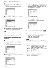
... . 000 000 . 000 . 000 . 000 Select Set ENTER Exit MENU 4 Set the three digit value (0 to the next box. The following menu appears on the screen. IP address error Gateway address error Primary DNS address error Secondary DNS address error Subnet mask error The following menu appears on the remote commander and press ENTER or ,. INITIAL SETUP/INFORMATION Manual IP Address: Subnet Mask: Gateway: Primay DNS...
... . 000 000 . 000 . 000 . 000 Select Set ENTER Exit MENU 4 Set the three digit value (0 to the next box. The following menu appears on the screen. IP address error Gateway address error Primary DNS address error Secondary DNS address error Subnet mask error The following menu appears on the remote commander and press ENTER or ,. INITIAL SETUP/INFORMATION Manual IP Address: Subnet Mask: Gateway: Primay DNS...

Operating Instructions
Page 42
... normal screen. PICTURE/SOUND CONTROL Picture Mode: Vivid Adjust Picture Adjust Sound Index Number 117 . . . 2 Input the index number of the display unit. You cannot change the index number" on the control button section of the display you change to operate using the Remote Commander. 1 Press MENU. Monitor index numbers appear in black characters on the lower left menu on the Remote Commander. The display returns to the Remote menu. The Remote menu appears on the Remote Commander. ON SET OFF To change the index number You can operate a specific display...
... normal screen. PICTURE/SOUND CONTROL Picture Mode: Vivid Adjust Picture Adjust Sound Index Number 117 . . . 2 Input the index number of the display unit. You cannot change the index number" on the control button section of the display you change to operate using the Remote Commander. 1 Press MENU. Monitor index numbers appear in black characters on the lower left menu on the Remote Commander. The display returns to the Remote menu. The Remote menu appears on the Remote Commander. ON SET OFF To change the index number You can operate a specific display...
Operating Instructions
Page 43
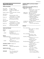
... 5⁄8 inches) Panel size 40-inch (diagonal 1016 mm) FWD-32LX1R: Pixel pitch Picture size Panel size 0.510 (horizontal) × 0.510 (vertical) mm (1⁄32 × 1⁄32 inches) 698 (horizontal) × 392 (vertical) mm (27 1⁄2 × 15 1⁄2 inches) 32-inch (diagonal 801 mm) Inputs and Outputs INPUT1 DVI AUDIO DVI (DVI Specification Rev. 1.0 compliant) Stereo minijack (×1) 500 mVrms, high impedance INPUT2 RGB/COMPONENT D-sub...
... 5⁄8 inches) Panel size 40-inch (diagonal 1016 mm) FWD-32LX1R: Pixel pitch Picture size Panel size 0.510 (horizontal) × 0.510 (vertical) mm (1⁄32 × 1⁄32 inches) 698 (horizontal) × 392 (vertical) mm (27 1⁄2 × 15 1⁄2 inches) 32-inch (diagonal 801 mm) Inputs and Outputs INPUT1 DVI AUDIO DVI (DVI Specification Rev. 1.0 compliant) Stereo minijack (×1) 500 mVrms, high impedance INPUT2 RGB/COMPONENT D-sub...

Brochure
Page 2
... control) Speakers: SS-SP32FW/S (Speakers for Black and Silver models), SS-SP32FW/W (Speakers for White Model) Software: PJNet (Asset Management tool to control up to 255 Sony Plasmas or Projectors), DCDS (Asset Management tool to schedule and control up to 15 degrees). Sony is a trademark of their respective owners. FWD-32LX1R LCD Pro Display specifications Screen Size: 32.0" Audio Power Output: 14W Total (7Wx2 Digital AMP) Cable Management System: Yes On Screen Controls: Yes Wall/Arm Mount: Yes Multiple Language Display...
... control) Speakers: SS-SP32FW/S (Speakers for Black and Silver models), SS-SP32FW/W (Speakers for White Model) Software: PJNet (Asset Management tool to control up to 255 Sony Plasmas or Projectors), DCDS (Asset Management tool to schedule and control up to 15 degrees). Sony is a trademark of their respective owners. FWD-32LX1R LCD Pro Display specifications Screen Size: 32.0" Audio Power Output: 14W Total (7Wx2 Digital AMP) Cable Management System: Yes On Screen Controls: Yes Wall/Arm Mount: Yes Multiple Language Display...

