
Instruction Manual
Page 2
... observe all warnings, precautions and instructions on the marking label. Use [ Power Sources This set should still fail to your home, consult your Sony dealer regarding this product. This plug will fit into the power outlet only one blade wider than the other sources, refer to them. Model No...any kind into the set through openings as they may touch dangerous voltage points or short out parts that may be of sufficient magnitude to persons. Record the serial number in the U.S.A. DSC-W35/W55 Serial No WARNING To reduce fire or shock hazard, do not expose the unit to insert ...
... observe all warnings, precautions and instructions on the marking label. Use [ Power Sources This set should still fail to your home, consult your Sony dealer regarding this product. This plug will fit into the power outlet only one blade wider than the other sources, refer to them. Model No...any kind into the set through openings as they may touch dangerous voltage points or short out parts that may be of sufficient magnitude to persons. Record the serial number in the U.S.A. DSC-W35/W55 Serial No WARNING To reduce fire or shock hazard, do not expose the unit to insert ...

Instruction Manual
Page 3
... attempt to service the set yourself as specified by the manufacturer) to determine that the set is in a confined space, such as the original parts. Never place the set in safe operating condition. 3 This will often require extensive work by placing the set on an unstable cart, stand, ... by the manufacturer that it . Improper adjustment of the set. Refer all servicing to qualified service personnel. [ Replacement parts When replacement parts are specified in cabinet, unless proper ventilation is provided. - Do not use power-line operated sets near a swimming pool, etc. [ Power-Cord ...
... attempt to service the set yourself as specified by the manufacturer) to determine that the set is in a confined space, such as the original parts. Never place the set in safe operating condition. 3 This will often require extensive work by placing the set on an unstable cart, stand, ... by the manufacturer that it . Improper adjustment of the set. Refer all servicing to qualified service personnel. [ Replacement parts When replacement parts are specified in cabinet, unless proper ventilation is provided. - Do not use power-line operated sets near a swimming pool, etc. [ Power-Cord ...

Instruction Manual
Page 4
.... 4 Operation is for the FCC related matters only. [ Regulatory Information Declaration of Conformity Trade Name: SONY Model No.: DSC-W55 Responsible Party: Sony Electronics Inc. For Customers in the U.S.A. Otherwise, fire or injury may not cause harmful interference, and ...(2) this first CAUTION Replace the battery with Part 15 of rechargeable batteries, call : Sony Customer Information Center 1-800-222-SONY (...
.... 4 Operation is for the FCC related matters only. [ Regulatory Information Declaration of Conformity Trade Name: SONY Model No.: DSC-W55 Responsible Party: Sony Electronics Inc. For Customers in the U.S.A. Otherwise, fire or injury may not cause harmful interference, and ...(2) this first CAUTION Replace the battery with Part 15 of rechargeable batteries, call : Sony Customer Information Center 1-800-222-SONY (...

Instruction Manual
Page 5
.... [ Note: This equipment has been tested and found compliant with the instructions, may cause harmful interference to Subpart B of Part 15 of materials will help prevent potential negative consequences for the recycling of electrical and electronic equipment. Consult the dealer or an... experienced radio/TV technician for a digital device pursuant to radio communications. For the State of Old Electrical & Electronic Equipment (Applicable in this manual could void your...
.... [ Note: This equipment has been tested and found compliant with the instructions, may cause harmful interference to Subpart B of Part 15 of materials will help prevent potential negative consequences for the recycling of electrical and electronic equipment. Consult the dealer or an... experienced radio/TV technician for a digital device pursuant to radio communications. For the State of Old Electrical & Electronic Equipment (Applicable in this manual could void your...

Service Manual
Page 1
Ne les remplacer que par une pièce portant le numéro spécifié. DSC-W55 SERVICE MANUAL Ver. 1.4 2007.09 Revision History How to use Acrobat Reader Internal memory ON BOARD Revised-2 Photo: Silver 2 LEVEL US Model Canadian ...Board The components identified by Kohda TEC Les composants identifiés par une marque 0 sont critiques pour la sécurité. DIGITAL STILL CAMERA DSC-W55_L2 9-852-160-33 Sony EMCS Co. 2007I0800-1 © 2007.09 Published by mark 0 or dotted line with part number specified. Replace only with mark 0 are critical for safety.
Ne les remplacer que par une pièce portant le numéro spécifié. DSC-W55 SERVICE MANUAL Ver. 1.4 2007.09 Revision History How to use Acrobat Reader Internal memory ON BOARD Revised-2 Photo: Silver 2 LEVEL US Model Canadian ...Board The components identified by Kohda TEC Les composants identifiés par une marque 0 sont critiques pour la sécurité. DIGITAL STILL CAMERA DSC-W55_L2 9-852-160-33 Sony EMCS Co. 2007I0800-1 © 2007.09 Published by mark 0 or dotted line with part number specified. Replace only with mark 0 are critical for safety.
Service Manual
Page 3
... LES NUMÉROS SONT DONNÉS DANS CE MANUEL OU DANS LES SUPPÉMENTS PUBLIÉS PAR SONY. Check the area of your repair for parts which, through functioning, show obvious signs of deterioration. Unleaded solder Boards requiring use of unleaded solder are "pinched".... Caution: The printed pattern (copper foil) may DSC-W55_L2 also be careful! • Strong viscosity circuit board (within 3 times). COMPONENTS IDENTIFIED BY MARK 0 OR DOTTED LINE WITH MARK 0 ON THE SCHEMATIC DIAGRAMS AND IN THE PARTS LIST ARE CRITICAL TO SAFE OPERATION. Look for unsoldered...
... LES NUMÉROS SONT DONNÉS DANS CE MANUEL OU DANS LES SUPPÉMENTS PUBLIÉS PAR SONY. Check the area of your repair for parts which, through functioning, show obvious signs of deterioration. Unleaded solder Boards requiring use of unleaded solder are "pinched".... Caution: The printed pattern (copper foil) may DSC-W55_L2 also be careful! • Strong viscosity circuit board (within 3 times). COMPONENTS IDENTIFIED BY MARK 0 OR DOTTED LINE WITH MARK 0 ON THE SCHEMATIC DIAGRAMS AND IN THE PARTS LIST ARE CRITICAL TO SAFE OPERATION. Look for unsoldered...

Service Manual
Page 4
Overall Block Diagram (2/2 3-2 3-3. Schematic Diagrams 4-3 4-3. Printed Wiring Boards 4-16 4-4. Mounted Parts Location 4-25 5. REPAIR PARTS LIST 5-1. BLOCK DIAGRAMS 3-1. PRINTED WIRING BOARDS AND SCHEMATIC DIAGRAMS 4-1. Disassembly 2-2 2-2. Exchange Method of Zoom Motor Unit 2-9 3. Overall Block Diagram ... 1-1. Method for Copying or Erasing the Data in Internal Memory 1-2 1-4. DISASSEMBLY 2-1. Exchange Method of Barrier Assy 2-6 2-3. Electrical Parts List 5-6 DSC-W55_L2 - 4 - Power Block Diagram 3-3 4. Process After Fixing Flash Error 1-1 1-3.
Overall Block Diagram (2/2 3-2 3-3. Schematic Diagrams 4-3 4-3. Printed Wiring Boards 4-16 4-4. Mounted Parts Location 4-25 5. REPAIR PARTS LIST 5-1. BLOCK DIAGRAMS 3-1. PRINTED WIRING BOARDS AND SCHEMATIC DIAGRAMS 4-1. Disassembly 2-2 2-2. Exchange Method of Zoom Motor Unit 2-9 3. Overall Block Diagram ... 1-1. Method for Copying or Erasing the Data in Internal Memory 1-2 1-4. DISASSEMBLY 2-1. Exchange Method of Barrier Assy 2-6 2-3. Electrical Parts List 5-6 DSC-W55_L2 - 4 - Power Block Diagram 3-3 4. Process After Fixing Flash Error 1-1 1-3.

Service Manual
Page 8
... Short Jig To preparing the short jig, a small clip is kept without discharging when the main power of connector. 2. Cut and remove the part of gilt which is attached to prevent electrical shock. 1 kΩ/1 W Note: High-voltage cautions Discharging the Capacitor Short-circuit between the two ...points with the short jig about 10 seconds. Wrap insulating tape. R:1 kΩ/1 W (Part code: 1-215-869-11) DSC-W55_L2 2-1 Wrap insulating tape fully around the leads of the ST-133 board is simply turned off at wire of the unit is...
... Short Jig To preparing the short jig, a small clip is kept without discharging when the main power of connector. 2. Cut and remove the part of gilt which is attached to prevent electrical shock. 1 kΩ/1 W Note: High-voltage cautions Discharging the Capacitor Short-circuit between the two ...points with the short jig about 10 seconds. Wrap insulating tape. R:1 kΩ/1 W (Part code: 1-215-869-11) DSC-W55_L2 2-1 Wrap insulating tape fully around the leads of the ST-133 board is simply turned off at wire of the unit is...

Service Manual
Page 13
... heating the portions 1 → 2 in the under figure one by one sequentially. * Discard the removed Ornamental Ring A. 1 2 Tip DSC-W55_L2 2-6 Beware of a burn since the entire Ornamental Ring becomes hot. * As the adhesive force of the group-1 frame. In case ...01) 1 2 3 2-2-1. Heat two circled portions (1, 2)with the soldering iron. 2-2. EXCHANGE METHOD OF BARRIER ASSY Service parts Part Number 1 2-673-650-01 2 2-673-652-01 3 2-673-651-01 Part Name Ring (A), Ornamental Barrier Assy Tapping screw (B1.2×4) Quantity 1 1 2 Tools used Torque driver Soldering iron Weight...
... heating the portions 1 → 2 in the under figure one by one sequentially. * Discard the removed Ornamental Ring A. 1 2 Tip DSC-W55_L2 2-6 Beware of a burn since the entire Ornamental Ring becomes hot. * As the adhesive force of the group-1 frame. In case ...01) 1 2 3 2-2-1. Heat two circled portions (1, 2)with the soldering iron. 2-2. EXCHANGE METHOD OF BARRIER ASSY Service parts Part Number 1 2-673-650-01 2 2-673-652-01 3 2-673-651-01 Part Name Ring (A), Ornamental Barrier Assy Tapping screw (B1.2×4) Quantity 1 1 2 Tools used Torque driver Soldering iron Weight...

Service Manual
Page 14
This is an important part to prevent the dust and light from coming in the lens barrel. 2-2-3. REMOVE OLD BARRIER ASSY 1 Remove two screws. * Discard the removed screws. 2 Remove the ... the ring, adjust the location of a projection to the lens direction. INSTALL NEW BARRIER ASSY 1 Install new Barrier Assy. 2 Tighten two screws. * Tightening torque = 0.5 kgf 1 2 2 DSC-W55_L2 2-7 2-2-2.
This is an important part to prevent the dust and light from coming in the lens barrel. 2-2-3. REMOVE OLD BARRIER ASSY 1 Remove two screws. * Discard the removed screws. 2 Remove the ... the ring, adjust the location of a projection to the lens direction. INSTALL NEW BARRIER ASSY 1 Install new Barrier Assy. 2 Tighten two screws. * Tightening torque = 0.5 kgf 1 2 2 DSC-W55_L2 2-7 2-2-2.

Service Manual
Page 15
... Ornamental Ring A so that the Ornamental Ring A does not float up . Put the 60g weight on the mold part of the Barrier Assy, the Ornamental Ring A will float up until the adhesive hardens. Not gap in the Ornamental ... must be tilted. Adhesive tape Completion after 30 minutes. Note: Be careful not to two recesses on a black mold part. ADHERE THE ORNAMENTAL RING A Apply an adhesive tape to give a shock. * After the weight was put the weight...group-1 frame, push the Ornamental Ring A into the group-1 frame. * The projection of the Barrier Assy. 2-2-4. DSC-W55_L2 2-8
... Ornamental Ring A so that the Ornamental Ring A does not float up . Put the 60g weight on the mold part of the Barrier Assy, the Ornamental Ring A will float up until the adhesive hardens. Not gap in the Ornamental ... must be tilted. Adhesive tape Completion after 30 minutes. Note: Be careful not to two recesses on a black mold part. ADHERE THE ORNAMENTAL RING A Apply an adhesive tape to give a shock. * After the weight was put the weight...group-1 frame, push the Ornamental Ring A into the group-1 frame. * The projection of the Barrier Assy. 2-2-4. DSC-W55_L2 2-8

Service Manual
Page 16
EXCHANGE METHOD OF ZOOM MOTOR UNIT Service parts Part Number 1 2-673-648-01 2 2-673-649-01 Part Name Zoom Motor Unit BT2 P1.4×3 B3C Quantity 1 2 Tools used Torque driver 2-3-1. INSTALL NEW ZOOM MOTOR UNIT 1 Install the Lens Flexible Board in new ...Zoom Motor Unit. 2 Install new Zoom Motor Unit in the Lens Block. 3 Tighten two screws. * Tightening torque = 0.7 kgf 2 1 1 1 DSC-W55_L2 2-9E 3 3 REMOVE...
EXCHANGE METHOD OF ZOOM MOTOR UNIT Service parts Part Number 1 2-673-648-01 2 2-673-649-01 Part Name Zoom Motor Unit BT2 P1.4×3 B3C Quantity 1 2 Tools used Torque driver 2-3-1. INSTALL NEW ZOOM MOTOR UNIT 1 Install the Lens Flexible Board in new ...Zoom Motor Unit. 2 Install new Zoom Motor Unit in the Lens Block. 3 Tighten two screws. * Tightening torque = 0.7 kgf 2 1 1 1 DSC-W55_L2 2-9E 3 3 REMOVE...
Service Manual
Page 26
... noted. Replace only with dusts nor exposed to strong light. 1. kΩ=1000 Ω, MΩ=1000 kΩ. • Caution when replacing chip parts. Example C541 L452 22U 10UH TA A 2520 Kinds of capacitor External dimensions (mm) Case size • Constants of resistors, capacitors, ICs and etc...;F unless otherwise noted. In addition, ensure that the output waveform of the lens L Camera 2. Ne les remplacer que par une pièce portant le numéro spécifie. DSC-W55_L2 4-3 a and the Fig. b can be attached after removal of tantalum capacitor...
... noted. Replace only with dusts nor exposed to strong light. 1. kΩ=1000 Ω, MΩ=1000 kΩ. • Caution when replacing chip parts. Example C541 L452 22U 10UH TA A 2520 Kinds of capacitor External dimensions (mm) Case size • Constants of resistors, capacitors, ICs and etc...;F unless otherwise noted. In addition, ensure that the output waveform of the lens L Camera 2. Ne les remplacer que par une pièce portant le numéro spécifie. DSC-W55_L2 4-3 a and the Fig. b can be attached after removal of tantalum capacitor...

Service Manual
Page 32
PRINTED WIRING BOARDS Link CD-604 FLEXIBLE BOARD ST-133 BOARD ST-134 FLEXIBLE BOARD SW-498 BOARD RL-074 FLEXIBLE BOARD MC-181 FLEXIBLE BOARD COMMON NOTE FOR PRINTED WIRING BOARDS MOUNTED PARTS LOCATION DSC-W55_L2 4-3.
PRINTED WIRING BOARDS Link CD-604 FLEXIBLE BOARD ST-133 BOARD ST-134 FLEXIBLE BOARD SW-498 BOARD RL-074 FLEXIBLE BOARD MC-181 FLEXIBLE BOARD COMMON NOTE FOR PRINTED WIRING BOARDS MOUNTED PARTS LOCATION DSC-W55_L2 4-3.

Service Manual
Page 33
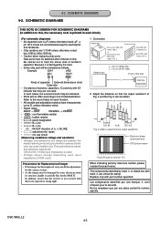
... (The other layers' patterns are not indicated) • Through hole is omitted. • There are a few cases that the part printed on diagram isn't mounted in this model. • C: panel designation • Chip parts. Transistor Diode C 654 456 5 4 4 5 3 3 3 123 BE 123 321 123 321 1 22 13 2 2 1 2 1 2 1 654 4 3 3 4 654 456 543 345 4 1 1 2 2 1 123...
... (The other layers' patterns are not indicated) • Through hole is omitted. • There are a few cases that the part printed on diagram isn't mounted in this model. • C: panel designation • Chip parts. Transistor Diode C 654 456 5 4 4 5 3 3 3 123 BE 123 321 123 321 1 22 13 2 2 1 2 1 2 1 654 4 3 3 4 654 456 543 345 4 1 1 2 2 1 123...

Service Manual
Page 39
DSC-W55_L2 Mounted parts location of the SY-176 board are not shown. Page 4-24 is not shown.
DSC-W55_L2 Mounted parts location of the SY-176 board are not shown. Page 4-24 is not shown.

Service Manual
Page 40
4-3. PRINTED WIRING BOARDS 4-4. MOUNTED PARTS LOCATION SW-498 BOARD BT001 B3 C001 C3 * CN003 A3 D001 A1 D002 A1 D003 B3 D004 C3 D005 B3 LND001 A2 LND002 A2 * LND003 A3 * LND004 B3 R001 D3 R002 C3 R003 C2 R004 B2 R005 B2 R006 C2 R007 A2 R008 A2 R009 A3 R010 A3 R011 A3 R012 A3 R013 A3 R014 A2 S001 D3 S002 B2 S003 A1 S004 C3 S005 D2 S006 C3 S007 C2 S008 C2 S009 C3 S010 A3 no mark : side A * mark : side B DSC-W55_L2 4-25E SW-498
4-3. PRINTED WIRING BOARDS 4-4. MOUNTED PARTS LOCATION SW-498 BOARD BT001 B3 C001 C3 * CN003 A3 D001 A1 D002 A1 D003 B3 D004 C3 D005 B3 LND001 A2 LND002 A2 * LND003 A3 * LND004 B3 R001 D3 R002 C3 R003 C2 R004 B2 R005 B2 R006 C2 R007 A2 R008 A2 R009 A3 R010 A3 R011 A3 R012 A3 R013 A3 R014 A2 S001 D3 S002 B2 S003 A1 S004 C3 S005 D2 S006 C3 S007 C2 S008 C2 S009 C3 S010 A3 no mark : side A * mark : side B DSC-W55_L2 4-25E SW-498

Service Manual
Page 41
Link EXPLODED VIEWS A CABINET BLOCK B LCD BLOCK C LENS BLOCK D BT HOLDER BLOCK Link ELECTRICAL PARTS LIST ACCESSORIES CD-604 FLEXIBLE BOARD C MC-181 FLEXIBLE BOARD D RL-074 FLEXIBLE BOARD B ST-133 BOARD C ST-134 FLEXIBLE BOARD C SW-498 BOARD B DSC-W55_L2 NOTE 5. REPAIR PARTS LIST NOTE: Characters A to Z of the electrical parts list indicate location of exploded views in which the desired part is shown.
Link EXPLODED VIEWS A CABINET BLOCK B LCD BLOCK C LENS BLOCK D BT HOLDER BLOCK Link ELECTRICAL PARTS LIST ACCESSORIES CD-604 FLEXIBLE BOARD C MC-181 FLEXIBLE BOARD D RL-074 FLEXIBLE BOARD B ST-133 BOARD C ST-134 FLEXIBLE BOARD C SW-498 BOARD B DSC-W55_L2 NOTE 5. REPAIR PARTS LIST NOTE: Characters A to Z of the electrical parts list indicate location of exploded views in which the desired part is shown.

Service Manual
Page 42
...in the exploded views are not supplied. • Due to standardization, replacements in the parts list may have some differences from the parts specified in ohms. METAL: metal-film resistor METAL OXIDE: Metal Oxide-film resistor F: ... Korea model NE : North European model TW : Taiwan model When indicating parts by mark 0 or dotted line with part number specified. REPAIR PARTS LIST NOTE: • -XX, -X mean standardized parts, so they are in the diagrams or the components used on the set... zz HK CH KR MY z zzz z zz z zzz z z zz zz z DSC-W55_L2 5-1 REPAIR PARTS LIST 5.
...in the exploded views are not supplied. • Due to standardization, replacements in the parts list may have some differences from the parts specified in ohms. METAL: metal-film resistor METAL OXIDE: Metal Oxide-film resistor F: ... Korea model NE : North European model TW : Taiwan model When indicating parts by mark 0 or dotted line with part number specified. REPAIR PARTS LIST NOTE: • -XX, -X mean standardized parts, so they are in the diagrams or the components used on the set... zz HK CH KR MY z zzz z zz z zzz z z zz zz z DSC-W55_L2 5-1 REPAIR PARTS LIST 5.

Service Manual
Page 43
... DISASSEMBLY HARDWARE LIST 2 #20 8 7 #20 1 #20 6 5 4 #20 #20 9 3 LCD Block (See page 5-3.) Ref. No. 1 1 1 1 2 Part No. No. 4 5 6 7 *8 Part No. Ver. 1.2 2007.06 5-1. Description X-2176-553-1 CABINET (FRONT) ASSY (240) (SILVER) X-2176-614-1 CABINET(FRONT) ASSY(240) (BLACK) X-2176-615-1 CABINET(FRONT) ASSY(240) (... LID (PLATE), DC 3-093-810-01 LABEL, FUSE RATING 9 3-100-146-01 SPACER (240), MOARE #20 2-635-591-31 SCREW(M1.4),NEW TRUSTAR P2 (Silver) DSC-W55_L2 5-2
... DISASSEMBLY HARDWARE LIST 2 #20 8 7 #20 1 #20 6 5 4 #20 #20 9 3 LCD Block (See page 5-3.) Ref. No. 1 1 1 1 2 Part No. No. 4 5 6 7 *8 Part No. Ver. 1.2 2007.06 5-1. Description X-2176-553-1 CABINET (FRONT) ASSY (240) (SILVER) X-2176-614-1 CABINET(FRONT) ASSY(240) (BLACK) X-2176-615-1 CABINET(FRONT) ASSY(240) (... LID (PLATE), DC 3-093-810-01 LABEL, FUSE RATING 9 3-100-146-01 SPACER (240), MOARE #20 2-635-591-31 SCREW(M1.4),NEW TRUSTAR P2 (Silver) DSC-W55_L2 5-2


