

User Guide
Page 3
... having one way. Cleaning Unplug the set . Use a cloth lightly dampened with a cloth or other ). The set may touch dangerous voltage points or short out parts that it is provided. - Never cover the slots and openings with water for future reference. This is not likely to have a suitable outlet installed. If...
... having one way. Cleaning Unplug the set . Use a cloth lightly dampened with a cloth or other ). The set may touch dangerous voltage points or short out parts that it is provided. - Never cover the slots and openings with water for future reference. This is not likely to have a suitable outlet installed. If...
User Guide
Page 4
...for long periods of time, unplug it from the wall outlet and refer servicing to determine that have fallen into the set. - Replacement parts When replacement parts are specified in the operating instructions. When the power cord or plug is left unattended and unused for service. If the set does ... to the set due to qualified service personnel. Adjust only those controls that are required, be sure the service technician has used replacement parts specified by the manufacturer that the set is in damage and will prevent damage to the set , ask the service technician to perform ...
...for long periods of time, unplug it from the wall outlet and refer servicing to determine that have fallen into the set. - Replacement parts When replacement parts are specified in the operating instructions. When the power cord or plug is left unattended and unused for service. If the set does ... to the set due to qualified service personnel. Adjust only those controls that are required, be sure the service technician has used replacement parts specified by the manufacturer that the set is in damage and will prevent damage to the set , ask the service technician to perform ...
User Guide
Page 5
... is for the FCC related matters only. Declaration of Conformity Trade Name: SONY Model No.:DSC-W30, DSC-W40 Responsible Party: Sony Electronics Inc. Declaration of rechargeable batteries, call : Sony Customer Information Services Center 1-800-222-SONY (7669) The number below is subject to the following two conditions: (1)... may not cause harmful interference, and (2) this first CAUTION Replace the battery with Part 15 of the FCC Rules. Telephone No.: 858-942-2230 This device complies with Part 15 of the FCC Rules. Telephone No.: 858-942-2230 This device complies with...
... is for the FCC related matters only. Declaration of Conformity Trade Name: SONY Model No.:DSC-W30, DSC-W40 Responsible Party: Sony Electronics Inc. Declaration of rechargeable batteries, call : Sony Customer Information Services Center 1-800-222-SONY (7669) The number below is subject to the following two conditions: (1)... may not cause harmful interference, and (2) this first CAUTION Replace the battery with Part 15 of the FCC Rules. Telephone No.: 858-942-2230 This device complies with Part 15 of the FCC Rules. Telephone No.: 858-942-2230 This device complies with...
User Guide
Page 6
...the instructions, may influence the picture and sound of this camera. If you purchased the product. If this product, please ...Equipment (Applicable in order to comply with the limits for a digital device pursuant to correct the interference by turning the equipment off ...rating as household waste. The recycling of materials will help to Part 15 of electrical and electronic equipment. Note: This equipment has been...antenna. - If the plug supplied with this equipment for your nearest Sony service station. 6 Notice If static electricity or electromagnetism causes data transfer ...
...the instructions, may influence the picture and sound of this camera. If you purchased the product. If this product, please ...Equipment (Applicable in order to comply with the limits for a digital device pursuant to correct the interference by turning the equipment off ...rating as household waste. The recycling of materials will help to Part 15 of electrical and electronic equipment. Note: This equipment has been...antenna. - If the plug supplied with this equipment for your nearest Sony service station. 6 Notice If static electricity or electromagnetism causes data transfer ...
User Guide
Page 10
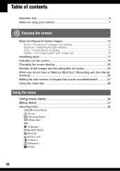
... (White Bal) ISO (P.Quality) Mode (REC Mode) M (Interval) (Flash Level) (Contrast) (Sharpness) (Setup) 10 On "image quality" and "image size 15 Identifying parts 17 Indicators on the screen 19 Changing the screen display 23 Number of still images and recording time of movies 24 When you do not... "Memory Stick Duo" (Recording with the internal memory 26 Battery life and number of lighting 15 Quality - Focusing on using your camera 7 Enjoying the camera Basic techniques for better images 13 Focus - Table of contents Read this first 5 Notes on a subject successfully 13 Exposure -
... (White Bal) ISO (P.Quality) Mode (REC Mode) M (Interval) (Flash Level) (Contrast) (Sharpness) (Setup) 10 On "image quality" and "image size 15 Identifying parts 17 Indicators on the screen 19 Changing the screen display 23 Number of still images and recording time of movies 24 When you do not... "Memory Stick Duo" (Recording with the internal memory 26 Battery life and number of lighting 15 Quality - Focusing on using your camera 7 Enjoying the camera Basic techniques for better images 13 Focus - Table of contents Read this first 5 Notes on a subject successfully 13 Exposure -
User Guide
Page 14
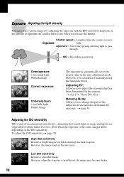
...an image pickup device (equivalent to the proper value in the auto adjustment mode. Adjusting EV: Allows you can create various images by the camera. Even when the exposure is the amount of the subject to be measured to determine the exposure. However, the image tends to adjust ...the exposure that the camera will receive when you to change the part of light that has been determined by adjusting the exposure and the ISO sensitivity. Exposure Adjusting the light intensity You can...
...an image pickup device (equivalent to the proper value in the auto adjustment mode. Adjusting EV: Allows you can create various images by the camera. Even when the exposure is the amount of the subject to be measured to determine the exposure. However, the image tends to adjust ...the exposure that the camera will receive when you to change the part of light that has been determined by adjusting the exposure and the ISO sensitivity. Exposure Adjusting the light intensity You can...
User Guide
Page 17
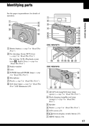
Identifying parts Enjoying the camera See the pages in "Read This First") E LCD screen (23) F (Screen display switch) button (23) G MENU button (30) 17 A E B F C G H D A Shutter button (t step 5 in "Read This ... (t step 2 in "Read This First") F Microphone G Flash (t step 5 in "Read This First") H Self-timer lamp (t step 5 in "Read This First")/AF illuminator (49) A B C D H I E J F K G L M N DSC-W50/W70 O P QR S T U DSC-W30/W40 I J VW X A AE/AF lock lamp/Self-timer lamp (green) (t step 5 in "Read This First") B Flash charging lamp/Record lamp (orange) (t step 5 in "Read...
Identifying parts Enjoying the camera See the pages in "Read This First") E LCD screen (23) F (Screen display switch) button (23) G MENU button (30) 17 A E B F C G H D A Shutter button (t step 5 in "Read This ... (t step 2 in "Read This First") F Microphone G Flash (t step 5 in "Read This First") H Self-timer lamp (t step 5 in "Read This First")/AF illuminator (49) A B C D H I E J F K G L M N DSC-W50/W70 O P QR S T U DSC-W30/W40 I J VW X A AE/AF lock lamp/Self-timer lamp (green) (t step 5 in "Read This First") B Flash charging lamp/Record lamp (orange) (t step 5 in "Read...

User Guide
Page 34
Spot (Spot metering) () Measures only a part of the subject. • This function is useful when the subject is backlit or when there is out of focus When ...page 30 z If the subject is strong contrast between the subject and the background. The camera determines a well-balanced exposure. • For details on the exposure t page 14 • When using [Center AF], the camera may not focus on a subject at the edge of the frame (or the screen), ... frame As long as you can retry the procedure as many times as follows. 1 Recompose the shot so that sets which part of the subject there.
Spot (Spot metering) () Measures only a part of the subject. • This function is useful when the subject is backlit or when there is out of focus When ...page 30 z If the subject is strong contrast between the subject and the background. The camera determines a well-balanced exposure. • For details on the exposure t page 14 • When using [Center AF], the camera may not focus on a subject at the edge of the frame (or the screen), ... frame As long as you can retry the procedure as many times as follows. 1 Recompose the shot so that sets which part of the subject there.
User Guide
Page 90
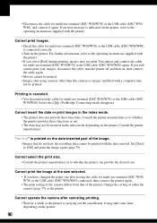
...the index mode depending on the date-inserted part of the image. • Images that of either the camera (page 75) or the printer. Cannot print images. • Check the cable for multi-use terminal (DSC-W50/ W70) or the USB cable (DSC-W30/W40) connected, then connect the printer again....carrying out the cancellation. Cannot operate the camera after having the cable for multi-use terminal (DSC-W50/W70) or the USB cable (DSC-W30/W40) is canceled. • You disconnected the cable for multi-use terminal (DSC-W50/W70) or the USB cable (DSC-W30/ W40), and connect it again. ...
...the index mode depending on the date-inserted part of the image. • Images that of either the camera (page 75) or the printer. Cannot print images. • Check the cable for multi-use terminal (DSC-W50/ W70) or the USB cable (DSC-W30/W40) connected, then connect the printer again....carrying out the cancellation. Cannot operate the camera after having the cable for multi-use terminal (DSC-W50/W70) or the USB cable (DSC-W30/W40) is canceled. • You disconnected the cable for multi-use terminal (DSC-W50/W70) or the USB cable (DSC-W30/ W40), and connect it again. ...

User Guide
Page 104
...Creating 51 Format 50, 51 Function Guide 48 H High sensitivity t step 5 in "Read This First" Histogram 23 Holding the camera t step 5 in "Read This First" I Identifying parts 17 Image file storage destinations and file names 64 Image quality 15, 36 Image size 15 t step 4 in "Read This ... 14 P PAL 55 Parallax 84 PC see "Computer" PictBridge 73 Pixel 15 Playback zoom t step 6 in "Read This First" Precautions 99 Precision digital zoom .......... 47 Pressing halfway down.........13 t step 5 in "Read This First" Print 72 Index mode 73 Single-image mode ....... 73 Print order mark...
...Creating 51 Format 50, 51 Function Guide 48 H High sensitivity t step 5 in "Read This First" Histogram 23 Holding the camera t step 5 in "Read This First" I Identifying parts 17 Image file storage destinations and file names 64 Image quality 15, 36 Image size 15 t step 4 in "Read This ... 14 P PAL 55 Parallax 84 PC see "Computer" PictBridge 73 Pixel 15 Playback zoom t step 6 in "Read This First" Precautions 99 Precision digital zoom .......... 47 Pressing halfway down.........13 t step 5 in "Read This First" Print 72 Index mode 73 Single-image mode ....... 73 Print order mark...

Service Manual
Page 1
... Revision History How to use Acrobat Reader Internal memory ON BOARD Revised-1 Replace the previously issued SERVICE MANUAL 9-876-935-31 with part number specified. DSC-W30/W40_L2 9-876-935-32 DIGITAL STILL CAMERA Sony EMCS Co. 2008I0500-1 © 2008.9 Published by mark 0 or dotted line with mark 0 are critical for safety. Les composants identifié...
... Revision History How to use Acrobat Reader Internal memory ON BOARD Revised-1 Replace the previously issued SERVICE MANUAL 9-876-935-31 with part number specified. DSC-W30/W40_L2 9-876-935-32 DIGITAL STILL CAMERA Sony EMCS Co. 2008I0500-1 © 2008.9 Published by mark 0 or dotted line with mark 0 are critical for safety. Les composants identifié...

Service Manual
Page 3
... Check the entire board surface for unsoldered or poorly-soldered connections. Look for unauthorized replacement parts, particularly transistors, that no lead. (Caution: Some printed circuit boards may DSC-W30/W40_L2 also be added to ordinary solder. - 3 - Point them out to the ...customer and recommend their replacement. 4. Soldering irons using a temperature regulator should be set to the customer. 1. REPLACE THESE COMPONENTS WITH SONY PARTS WHOSE PART NUMBERS APPEAR AS...
... Check the entire board surface for unsoldered or poorly-soldered connections. Look for unauthorized replacement parts, particularly transistors, that no lead. (Caution: Some printed circuit boards may DSC-W30/W40_L2 also be added to ordinary solder. - 3 - Point them out to the ...customer and recommend their replacement. 4. Soldering irons using a temperature regulator should be set to the customer. 1. REPLACE THESE COMPONENTS WITH SONY PARTS WHOSE PART NUMBERS APPEAR AS...

Service Manual
Page 4
...-diagnosis Display 1-1 1-2. Exchange Method of Zoom Motor Unit 2-9 3. Exchange Method of Barrier Assy 2-6 2-3. Overall Block Diagram (2/2 3-2 3-3. Frame Schematic Diagram 4-1 4-2. Exploded Views 5-2 5-2. Electrical Parts List 5-6 DSC-W30/W40_L2 - 4 - Mounted Parts Location 4-26 5. REPAIR PARTS LIST 5-1. Description on Replacing the SY-143 Board 1-3 2. Disassembly 2-2 2-2. Printed Wiring Boards 4-17 4-4. Process After Fixing Flash Error 1-1 1-3. Overall Block Diagram (1/2 3-1 3-2. Section...
...-diagnosis Display 1-1 1-2. Exchange Method of Zoom Motor Unit 2-9 3. Exchange Method of Barrier Assy 2-6 2-3. Overall Block Diagram (2/2 3-2 3-3. Frame Schematic Diagram 4-1 4-2. Exploded Views 5-2 5-2. Electrical Parts List 5-6 DSC-W30/W40_L2 - 4 - Mounted Parts Location 4-26 5. REPAIR PARTS LIST 5-1. Description on Replacing the SY-143 Board 1-3 2. Disassembly 2-2 2-2. Printed Wiring Boards 4-17 4-4. Process After Fixing Flash Error 1-1 1-3. Overall Block Diagram (1/2 3-1 3-2. Section...

Service Manual
Page 9
... capacitor (C901) of the ST-133 board is snapped. • When installing a connector, dont' press down at wire of connector. R:1 kΩ/1 W (Part code: 1-215-869-11) DSC-W30/W40_L2 2-1 2. Wrap insulating tape fully around the leads of the unit is snapped. • Do not apply excessive load to each end of...8486;/1 W Note: High-voltage cautions Discharging the Capacitor Short-circuit between the two points with the short jig about 10 seconds. Cut and remove the part of gilt which is kept without discharging when the main power of the resistor to the maximum 300 V potential.
... capacitor (C901) of the ST-133 board is snapped. • When installing a connector, dont' press down at wire of connector. R:1 kΩ/1 W (Part code: 1-215-869-11) DSC-W30/W40_L2 2-1 2. Wrap insulating tape fully around the leads of the unit is snapped. • Do not apply excessive load to each end of...8486;/1 W Note: High-voltage cautions Discharging the Capacitor Short-circuit between the two points with the short jig about 10 seconds. Cut and remove the part of gilt which is kept without discharging when the main power of the resistor to the maximum 300 V potential.

Service Manual
Page 14
... peeled while heating the portions 1 → 2 in the under figure one by one sequentially. * Discard the removed Ornamental Ring A. 1 2 Tip DSC-W30/W40_L2 2-6 into a notch of the group-1 frame and prize the ring. * Take extreme care so as not to weaken the adhesive force. Insert ...coated surface of difficult peeling, heat the ring again with the soldering iron. EXCHANGE METHOD OF BARRIER ASSY Service parts Part Number 1 2-673-650-01 2 2-673-652-01 3 2-673-651-01 Part Name Ring (A), Ornamental Barrier Assy Tapping screw (B1.2×4) Quantity 1 1 2 Tools used Torque driver ...
... peeled while heating the portions 1 → 2 in the under figure one by one sequentially. * Discard the removed Ornamental Ring A. 1 2 Tip DSC-W30/W40_L2 2-6 into a notch of the group-1 frame and prize the ring. * Take extreme care so as not to weaken the adhesive force. Insert ...coated surface of difficult peeling, heat the ring again with the soldering iron. EXCHANGE METHOD OF BARRIER ASSY Service parts Part Number 1 2-673-650-01 2 2-673-652-01 3 2-673-651-01 Part Name Ring (A), Ornamental Barrier Assy Tapping screw (B1.2×4) Quantity 1 1 2 Tools used Torque driver ...

Service Manual
Page 15
This is an important part to prevent the dust and light from coming in. * After removing the Barrier Assy, take extreme care not to the lens direction. INSTALL NEW BARRIER ASSY 1 Install new Barrier Assy. 2 Tighten two screws. * Tightening torque = 0.5 kgf 1 2 2 DSC-W30/W40_L2 2-7 In returning the ring, adjust the location of a projection to...
This is an important part to prevent the dust and light from coming in. * After removing the Barrier Assy, take extreme care not to the lens direction. INSTALL NEW BARRIER ASSY 1 Install new Barrier Assy. 2 Tighten two screws. * Tightening torque = 0.5 kgf 1 2 2 DSC-W30/W40_L2 2-7 In returning the ring, adjust the location of a projection to...

Service Manual
Page 16
... projection of the spring for preventing static electricity must push in the Ornamental Ring A only. Note: Be careful not to two recesses on a black mold part. Not gap in full circumference between Ornamental Ring A and group-1 frame. ADHERE THE ORNAMENTAL RING A Apply an adhesive tape to give a shock. *... the top surface of the Barrier Assy, the Ornamental Ring A will float up until the adhesive hardens. 2-2-4. Put the 60g weight on the mold part of the Barrier Assy. If the weight is put on the Ornamental Ring A so that the Ornamental Ring A does not float up . A gap...
... projection of the spring for preventing static electricity must push in the Ornamental Ring A only. Note: Be careful not to two recesses on a black mold part. Not gap in full circumference between Ornamental Ring A and group-1 frame. ADHERE THE ORNAMENTAL RING A Apply an adhesive tape to give a shock. *... the top surface of the Barrier Assy, the Ornamental Ring A will float up until the adhesive hardens. 2-2-4. Put the 60g weight on the mold part of the Barrier Assy. If the weight is put on the Ornamental Ring A so that the Ornamental Ring A does not float up . A gap...

Service Manual
Page 17
... Motor Unit. 2 Install new Zoom Motor Unit in the Lens Block. 3 Tighten two screws. * Tightening torque = 0.7 kgf 2 1 1 1 DSC-W30/W40_L2 2-9E 3 3 EXCHANGE METHOD OF ZOOM MOTOR UNIT Service parts Part Number 1 2-673-648-01 2 2-673-649-01 Part Name Zoom Motor Unit BT2 P1.4×3 B3C Quantity 1 2 Tools used Torque driver 1 2 2-3-1. REMOVE OLD ZOOM MOTOR...
... Motor Unit. 2 Install new Zoom Motor Unit in the Lens Block. 3 Tighten two screws. * Tightening torque = 0.7 kgf 2 1 1 1 DSC-W30/W40_L2 2-9E 3 3 EXCHANGE METHOD OF ZOOM MOTOR UNIT Service parts Part Number 1 2-673-648-01 2 2-673-649-01 Part Name Zoom Motor Unit BT2 P1.4×3 B3C Quantity 1 2 Tools used Torque driver 1 2 2-3-1. REMOVE OLD ZOOM MOTOR...

Service Manual
Page 25
...they are not used .) Precautions for electrolytics and tantalums. • Chip resistors are in µF unless otherwise noted. Replace only with part number specified. DSC-W30/W40_L2 4-3 pF : µ µF. 50 V or less are critical for each block) (For schematic diagrams) • All ... not use circuit (Measuring conditions voltage and waveform) • Voltages and waveforms are measured between the measurement points and ground when camera shoots color bar chart of pattern box.They are reference values and reference waveforms. (VOM of DC 10 MΩ input impedance...
...they are not used .) Precautions for electrolytics and tantalums. • Chip resistors are in µF unless otherwise noted. Replace only with part number specified. DSC-W30/W40_L2 4-3 pF : µ µF. 50 V or less are critical for each block) (For schematic diagrams) • All ... not use circuit (Measuring conditions voltage and waveform) • Voltages and waveforms are measured between the measurement points and ground when camera shoots color bar chart of pattern box.They are reference values and reference waveforms. (VOM of DC 10 MΩ input impedance...

Service Manual
Page 31
PRINTED WIRING BOARDS Link CD-604 FLEXIBLE BOARD ST-133 BOARD ST-134 FLEXIBLE BOARD SW-462 BOARD RL-065 FLEXIBLE BOARD JK-302 FLEXIBLE BOARD DC-104 FLEXIBLE BOARD COMMON NOTE FOR PRINTED WIRING BOARDS MOUNTED PARTS LOCATION DSC-W30/W40_L2 4-3.
PRINTED WIRING BOARDS Link CD-604 FLEXIBLE BOARD ST-133 BOARD ST-134 FLEXIBLE BOARD SW-462 BOARD RL-065 FLEXIBLE BOARD JK-302 FLEXIBLE BOARD DC-104 FLEXIBLE BOARD COMMON NOTE FOR PRINTED WIRING BOARDS MOUNTED PARTS LOCATION DSC-W30/W40_L2 4-3.


