Instructions Manual
Page 1
Model No. STR-DG910 ©2007 Sony Corporation Refer to them whenever you call upon your Sony dealer regarding this product. Serial No. 3-094-430-11(1) Multi Channel AV Receiver Operating Instructions Owner's Record The model and serial numbers are located on the rear of the unit. Record the serial number in the space provided below.
Model No. STR-DG910 ©2007 Sony Corporation Refer to them whenever you call upon your Sony dealer regarding this product. Serial No. 3-094-430-11(1) Multi Channel AV Receiver Operating Instructions Owner's Record The model and serial numbers are located on the rear of the unit. Record the serial number in the space provided below.

Instructions Manual
Page 2
... energy and, if not installed and used in the event of cable entry as close to radio or television reception, which the receiver is encouraged to try to the grounding system of the building, as practical. 2US If this equipment does cause harmful interference to ...cautioned that to which can be unplugged from that any changes or modification not expressly approved in a residential installation. Reorient or relocate the receiving antenna. - Note to CATV system installer: This reminder is no guarantee that the cable ground shall be connected to correct the interference ...
... energy and, if not installed and used in the event of cable entry as close to radio or television reception, which the receiver is encouraged to try to the grounding system of the building, as practical. 2US If this equipment does cause harmful interference to ...cautioned that to which can be unplugged from that any changes or modification not expressly approved in a residential installation. Reorient or relocate the receiving antenna. - Note to CATV system installer: This reminder is no guarantee that the cable ground shall be connected to correct the interference ...
Instructions Manual
Page 3
...on the remote. "96/24" is a registered trademark of DTS, Inc. This receiver incorporates High-Definition Multimedia Interface (HDMITM) technology. Sony Corporation hereby grants the user a nonexclusive, non-transferable, limited license right to use the...HDMI, the HDMI logo and High-Definition Multimedia Interface are registered trademarks of Neural Audio Corporation. 3US This receiver incorporates Dolby* Digital and Pro Logic Surround and the DTS** Digital Surround System. * Manufactured under license ...About This Manual • The instructions in this manual are for model STR-DG910.
...on the remote. "96/24" is a registered trademark of DTS, Inc. This receiver incorporates High-Definition Multimedia Interface (HDMITM) technology. Sony Corporation hereby grants the user a nonexclusive, non-transferable, limited license right to use the...HDMI, the HDMI logo and High-Definition Multimedia Interface are registered trademarks of Neural Audio Corporation. 3US This receiver incorporates Dolby* Digital and Pro Logic Surround and the DTS** Digital Surround System. * Manufactured under license ...About This Manual • The instructions in this manual are for model STR-DG910.
Instructions Manual
Page 4
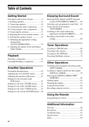
... 2: Connecting speakers 16 3a: Connecting the audio components.........17 3b: Connecting the video components ........20 4: Connecting the antennas 31 5: Preparing the receiver and the remote .....32 6: Selecting the speaker system 33 7: Calibrating the appropriate settings automatically (AUTO CALIBRATION 34 8: Adjusting the speaker levels and...DMPORT 80 Naming inputs 83 Changing the display 83 Using the Sleep Timer 84 Recording using the receiver 84 Using the Remote Programming the remote 85 Additional Information Glossary 90 Precautions 92 Troubleshooting 93 Specifications 97 Index 99 ...
... 2: Connecting speakers 16 3a: Connecting the audio components.........17 3b: Connecting the video components ........20 4: Connecting the antennas 31 5: Preparing the receiver and the remote .....32 6: Selecting the speaker system 33 7: Calibrating the appropriate settings automatically (AUTO CALIBRATION 34 8: Adjusting the speaker levels and...DMPORT 80 Naming inputs 83 Changing the display 83 Using the Sleep Timer 84 Recording using the receiver 84 Using the Remote Programming the remote 85 Additional Information Glossary 90 Precautions 92 Troubleshooting 93 Specifications 97 Index 99 ...

Instructions Manual
Page 5
...the level (page 46). qa ?/1 SPEAKERS (OFF/A/B/A+B) TONE MODE TONE TUNING MODE TUNING AUTO CAL MIC PHONES VIDEO 3 IN/PORTABLE AV IN VIDEO L AUDIO R MULTI CHANNEL DECODING DISPLAY INPUT MODE INPUT SELECTOR MASTER VOLUME MEMORY/ CATEGORY ENTER MODE CATEGORY 2CH A.F.D. Press...qk qj qh . D TUNING MODE E TUNING +/- to select the tuning mode (page 67, 69, 72-74). H Remote sensor Receives signals from remote commander. Getting Started Getting Started Description and location of selectable items appears here (page 7). Adjusts the tonal quality (bass/...
...the level (page 46). qa ?/1 SPEAKERS (OFF/A/B/A+B) TONE MODE TONE TUNING MODE TUNING AUTO CAL MIC PHONES VIDEO 3 IN/PORTABLE AV IN VIDEO L AUDIO R MULTI CHANNEL DECODING DISPLAY INPUT MODE INPUT SELECTOR MASTER VOLUME MEMORY/ CATEGORY ENTER MODE CATEGORY 2CH A.F.D. Press...qk qj qh . D TUNING MODE E TUNING +/- to select the tuning mode (page 67, 69, 72-74). H Remote sensor Receives signals from remote commander. Getting Started Getting Started Description and location of selectable items appears here (page 7). Adjusts the tonal quality (bass/...
Instructions Manual
Page 7
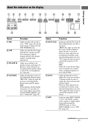
...button. D (EX) Function Lights up when the Pro Logic IIx Movie/Music/ Game decoder is decoding Dolby Digital Surround EX signals. Lights up when the receiver is activated. D EX ; PL IIx ; However, these indicators do not light up if both the center and surround speakers are connected. D EX" ...lights up when the receiver is set to "OPT IN" (page 78). Name E ; Lights up when the Pro Logic II Movie/Music/Game decoder is a digital signal being reproduced...
...button. D (EX) Function Lights up when the Pro Logic IIx Movie/Music/ Game decoder is decoding Dolby Digital Surround EX signals. Lights up when the receiver is activated. D EX ; PL IIx ; However, these indicators do not light up if both the center and surround speakers are connected. D EX" ...lights up when the receiver is set to "OPT IN" (page 78). Name E ; Lights up when the Pro Logic II Movie/Music/Game decoder is a digital signal being reproduced...
Instructions Manual
Page 8
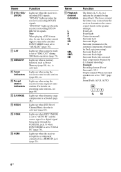
... H DTS (-ES)/ (96/24) I CAT J MEMORY K Tuner indicators L Preset station indicators M D.RANGE N NEO:6 O COAX P HDMI Function Lights up when the receiver recognizes a component connected via a HDMI IN jack (page 21). Note When playing a DTS format disc, be sure that you have made digital connections and that...signals. AUTO SW LCR SL SR 8US "DTS 96/24" lights up when dynamic range compression is activated. Lights up when using the receiver to "ONE CAT" during XM Radio operation (page 73). Front Left Front Right Center (monaural) Surround Left Surround Right Surround (monaural ...
... H DTS (-ES)/ (96/24) I CAT J MEMORY K Tuner indicators L Preset station indicators M D.RANGE N NEO:6 O COAX P HDMI Function Lights up when the receiver recognizes a component connected via a HDMI IN jack (page 21). Note When playing a DTS format disc, be sure that you have made digital connections and that...signals. AUTO SW LCR SL SR 8US "DTS 96/24" lights up when dynamic range compression is activated. Lights up when using the receiver to "ONE CAT" during XM Radio operation (page 73). Front Left Front Right Center (monaural) Surround Left Surround Right Surround (monaural ...
Instructions Manual
Page 9
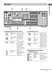
HDMI IN/ OUT jacks* Connects to a TV or a projector (page 21). Connects to the AM loop antenna supplied with this receiver (page 31). The image and the sound are output to a DVD player, satellite tuner, or a Blu-ray disc player. Connects to a DVD jacks player... 25, 27). C COMPONENT VIDEO INPUT/ OUTPUT section Green (Y) Blue (PB/CB) Red (PR/CR) COMPONENT Connects to the FM wire antenna supplied with this receiver (page 31). DMPORT jack Connects to a DIGITAL MEDIA PORT adapter (page 81). 4 B ANTENNA section FM ANTENNA jack AM ANTENNA terminals XM jack Connects to a...
HDMI IN/ OUT jacks* Connects to a TV or a projector (page 21). Connects to the AM loop antenna supplied with this receiver (page 31). The image and the sound are output to a DVD player, satellite tuner, or a Blu-ray disc player. Connects to a DVD jacks player... 25, 27). C COMPONENT VIDEO INPUT/ OUTPUT section Green (Y) Blue (PB/CB) Red (PR/CR) COMPONENT Connects to the FM wire antenna supplied with this receiver (page 31). DMPORT jack Connects to a DIGITAL MEDIA PORT adapter (page 81). 4 B ANTENNA section FM ANTENNA jack AM ANTENNA terminals XM jack Connects to a...

Instructions Manual
Page 10
...etc. (page 18, 19, 23). * You can use the supplied remote to operate the receiver and to control the Sony audio/video components that the remote is assigned to a TV (page 23). RM-AAP016 wk wj...video and audio jacks of a VCR, DVD player, etc. (page 25 - 28). Connects to control non-Sony audio/video components. Remote commander You can watch the selected input image when you connect the HDMI OUT or .... ql qk qj qh qg TV RM SET UP AV ?/1 ?/1 SYSTEM STANDBY VIDEO 1 VIDEO 2 VIDEO 3 DVD SAT TV SA-CD/CD TUNER AUX DMPORT RECEIVER 2CH A.F.D. For details, see "Programming the remote" ...
...etc. (page 18, 19, 23). * You can use the supplied remote to operate the receiver and to control the Sony audio/video components that the remote is assigned to a TV (page 23). RM-AAP016 wk wj...video and audio jacks of a VCR, DVD player, etc. (page 25 - 28). Connects to control non-Sony audio/video components. Remote commander You can watch the selected input image when you connect the HDMI OUT or .... ql qk qj qh qg TV RM SET UP AV ?/1 ?/1 SYSTEM STANDBY VIDEO 1 VIDEO 2 VIDEO 3 DVD SAT TV SA-CD/CD TUNER AUX DMPORT RECEIVER 2CH A.F.D. For details, see "Programming the remote" ...
Instructions Manual
Page 11
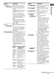
...are factory assigned to activate the Auto Calibration function. Press to control Sony components as follows. Press 0/10 to use. select channel numbers of the input buttons, the receiver turns on. Getting Started Name Function A AV ?/1 Press to turn on or off . To turn off all ..., satellite tuner, DVD/VHS COMBO, or DVD/HDD COMBO. Press to - Press to control non-Sony components following the steps in tuner AUX Not assigned DMPORT DIGITAL MEDIA PORT adapter Name D RECEIVER E D.TUNING F AUTO CAL G Numeric buttons (number 5a)) H ENTER MEMORY I DISPLAY Function Press...
...are factory assigned to activate the Auto Calibration function. Press to control Sony components as follows. Press 0/10 to use. select channel numbers of the input buttons, the receiver turns on. Getting Started Name Function A AV ?/1 Press to turn on or off . To turn off all ..., satellite tuner, DVD/VHS COMBO, or DVD/HDD COMBO. Press to - Press to control non-Sony components following the steps in tuner AUX Not assigned DMPORT DIGITAL MEDIA PORT adapter Name D RECEIVER E D.TUNING F AUTO CAL G Numeric buttons (number 5a)) H ENTER MEMORY I DISPLAY Function Press...
Instructions Manual
Page 12
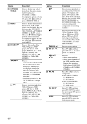
...deck, Blu-ray disc recorder, PSX, DVD/VHS COMBO, or DVD/HDD COMBO. (Also starts recording with components in the forward/ backward direction of the receiver, VCR, DVD player, satellite tuner, Blu-ray disc recorder, PSX, DVD/ VHS COMBO, or DVD/HDD COMBO on the TV screen. to display and... perform menu operations. Press to select the wide picture mode. 12US select preset stations. - search tracks in recording standby.) Press to start playback of Sony TV, press TV (wj) and then press MENU. Press to skip tracks of the VCR, DAT deck, or tape deck. Press to display the...
...deck, Blu-ray disc recorder, PSX, DVD/VHS COMBO, or DVD/HDD COMBO. (Also starts recording with components in the forward/ backward direction of the receiver, VCR, DVD player, satellite tuner, Blu-ray disc recorder, PSX, DVD/ VHS COMBO, or DVD/HDD COMBO on the TV screen. to display and... perform menu operations. Press to select the wide picture mode. 12US select preset stations. - search tracks in recording standby.) Press to start playback of Sony TV, press TV (wj) and then press MENU. Press to skip tracks of the VCR, DAT deck, or tape deck. Press to display the...
Instructions Manual
Page 13
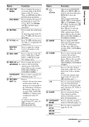
...on the TV screen. Name U , V/v/B/b V GUIDE W CLEAR -/-- >10 X SLEEP Y CATEGORY MODE Z 2CH A.F.D. Press to activate the Sleep Timer function and the duration which the receiver turns off automatically. Press to select the channel entry mode, either one or two digit of the CD player, VCD player, LD player, MD deck.... Press to the previous menu of the CD player, VCD player, DVD player, or MD deck (multidisc changer only). To return to skip disc of Sony TV, press TV (wj) and then press RETURN/EXIT O. Press also to enter the selection of the TV, press TV (wj) and then press ...
...on the TV screen. Name U , V/v/B/b V GUIDE W CLEAR -/-- >10 X SLEEP Y CATEGORY MODE Z 2CH A.F.D. Press to activate the Sleep Timer function and the duration which the receiver turns off automatically. Press to select the channel entry mode, either one or two digit of the CD player, VCD player, LD player, MD deck.... Press to the previous menu of the CD player, VCD player, DVD player, or MD deck (multidisc changer only). To return to skip disc of Sony TV, press TV (wj) and then press RETURN/EXIT O. Press also to enter the selection of the TV, press TV (wj) and then press ...
Instructions Manual
Page 14
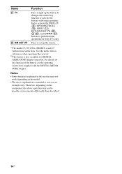
... + and H buttons have tactile dots. It also activate the DISPLAY (I), OPTIONS TOOLS (J), MENU (K), RETURN/EXIT O (T), (U), and V/v/B/b (U) buttons to serve as references when operating the receiver. Therefore, depending on the function of the button, see the operating instructions supplied with orange printing. b)This button is intended to perform menu operations for... DIGITAL MEDIA PORT adapter operation. For details on the component, the above explanation is also available for Sony TVs only. Use the tactile dots as an example only.
... + and H buttons have tactile dots. It also activate the DISPLAY (I), OPTIONS TOOLS (J), MENU (K), RETURN/EXIT O (T), (U), and V/v/B/b (U) buttons to serve as references when operating the receiver. Therefore, depending on the function of the button, see the operating instructions supplied with orange printing. b)This button is intended to perform menu operations for... DIGITAL MEDIA PORT adapter operation. For details on the component, the above explanation is also available for Sony TVs only. Use the tactile dots as an example only.

Instructions Manual
Page 15
... of DVD software recorded sound in the Surround EX format if you to use a 7 channel speaker with 4 sub woofer system. Getting Started 1: Installing speakers This receiver allows you connect one additional surround back speaker (6.1 channel) or two surround back speakers (7.1 channel) (see "Using the surround back decoding mode" on page 52...
... of DVD software recorded sound in the Surround EX format if you to use a 7 channel speaker with 4 sub woofer system. Getting Started 1: Installing speakers This receiver allows you connect one additional surround back speaker (6.1 channel) or two surround back speakers (7.1 channel) (see "Using the surround back decoding mode" on page 52...

Instructions Manual
Page 17
... deck, etc. d)When you connect only one surround back speaker, connect it to the SPEAKERS SURROUND BACK L terminals. After connecting your audio components to this receiver. b)Model equipped only with DIGITAL COAXIAL OUTPUT jack etc. b)If you have an additional front speaker system, connect them to the SPEAKERS FRONT B terminals. c)If... 20) or "4: Connecting the antennas" (page 31). If the auto standby function is set to on, it turns to standby mode automatically based on the receiver (page 33).
... deck, etc. d)When you connect only one surround back speaker, connect it to the SPEAKERS SURROUND BACK L terminals. After connecting your audio components to this receiver. b)Model equipped only with DIGITAL COAXIAL OUTPUT jack etc. b)If you have an additional front speaker system, connect them to the SPEAKERS FRONT B terminals. c)If... 20) or "4: Connecting the antennas" (page 31). If the auto standby function is set to on, it turns to standby mode automatically based on the receiver (page 33).

Instructions Manual
Page 18
... jacks are compatible with digital audio output jack The following illustration shows how to SA-CD/CD/CD-R IN jacks (analog input jack) on this receiver. Super Audio CD player/ CD player/ CD recorder A B DIGITAL (ASSIGNABLE) SAT IN VIDEO 2/ BD IN VIDEO 1 IN OPTICAL SA-CD/ CD/CD-R IN DVD IN...; When you play back a Super Audio CD disc on a Super Audio CD player, the sound is output only if you make analog recording on the receiver.
... jacks are compatible with digital audio output jack The following illustration shows how to SA-CD/CD/CD-R IN jacks (analog input jack) on this receiver. Super Audio CD player/ CD player/ CD recorder A B DIGITAL (ASSIGNABLE) SAT IN VIDEO 2/ BD IN VIDEO 1 IN OPTICAL SA-CD/ CD/CD-R IN DVD IN...; When you play back a Super Audio CD disc on a Super Audio CD player, the sound is output only if you make analog recording on the receiver.

Instructions Manual
Page 20
...; Connect image display components such as a TV or a projector to the HDMI OUT or MONITOR OUT jack on the receiver. • Be sure to this receiver. Component to be connected Component Page With HDMI jack 21 TV 23 DVD player/DVD recorder 25 Satellite tuner/Set-top box... 28 Video input/output jack to connect each component. After connecting all your components, proceed to the illustration that follows. Converting video signals This receiver is transmitted. For details, see page 29. 20US Before you begin, refer to "Component to be connected The image quality depends on , ...
...; Connect image display components such as a TV or a projector to the HDMI OUT or MONITOR OUT jack on the receiver. • Be sure to this receiver. Component to be connected Component Page With HDMI jack 21 TV 23 DVD player/DVD recorder 25 Satellite tuner/Set-top box... 28 Video input/output jack to connect each component. After connecting all your components, proceed to the illustration that follows. Converting video signals This receiver is transmitted. For details, see page 29. 20US Before you begin, refer to "Component to be connected The image quality depends on , ...
Instructions Manual
Page 21
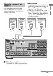
...Started Connecting components with HDMI jacks HDMI is converted. This signal supports Dolby Digital, DTS, and linear PCM. • Analog video signals input to the receiver. Audio/video signals A A A A DIGITAL (ASSIGNABLE) SAT IN VIDEO 2/ BD IN VIDEO 1 IN OPTICAL SA-CD/ CD/CD-R IN DVD IN...2/BD VIDEO 1 AUDIO OUT SUB WOOFER CENTER R SURROUND BACK SPEAKERS R SURROUND A HDMI cable (not supplied) We recommend that you use a Sony HDMI cable. Blu-ray disc player Audio/video signals TV, projector, etc. Audio signals are not output from the speakers connected to the VIDEO ...
...Started Connecting components with HDMI jacks HDMI is converted. This signal supports Dolby Digital, DTS, and linear PCM. • Analog video signals input to the receiver. Audio/video signals A A A A DIGITAL (ASSIGNABLE) SAT IN VIDEO 2/ BD IN VIDEO 1 IN OPTICAL SA-CD/ CD/CD-R IN DVD IN...2/BD VIDEO 1 AUDIO OUT SUB WOOFER CENTER R SURROUND BACK SPEAKERS R SURROUND A HDMI cable (not supplied) We recommend that you use a Sony HDMI cable. Blu-ray disc player Audio/video signals TV, projector, etc. Audio signals are not output from the speakers connected to the VIDEO ...
Instructions Manual
Page 22
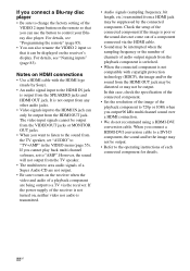
..., see "Naming inputs" (page 83). When you connect a HDMI-DVI conversion cable to a DVI-D component, the sound and/or the image may be suppressed by Sony). • An audio signal input to the HDMI IN jack is not compatible with the HDMI logo (made by the connected component. For details, see... player • Be sure to change the factory setting of the VIDEO 2 input button on the remote so that it can be displayed on the receiver's display. In this case, check the specification of the connected component. • Set the resolution of the image of the playback component to 720p or...
..., see "Naming inputs" (page 83). When you connect a HDMI-DVI conversion cable to a DVI-D component, the sound and/or the image may be suppressed by Sony). • An audio signal input to the HDMI IN jack is not compatible with the HDMI logo (made by the connected component. For details, see... player • Be sure to change the factory setting of the VIDEO 2 input button on the remote so that it can be displayed on the receiver's display. In this case, check the specification of the connected component. • Set the resolution of the image of the playback component to 720p or...
Instructions Manual
Page 23
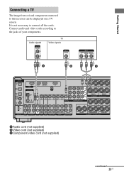
... supplied) continued 23US It is not necessary to the jacks of your components. Getting Started Connecting a TV The image from a visual component connected to this receiver can be displayed on a TV screen.
... supplied) continued 23US It is not necessary to the jacks of your components. Getting Started Connecting a TV The image from a visual component connected to this receiver can be displayed on a TV screen.


