Operating Instructions
Page 1
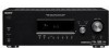
Record the serial number in the space provided below. Refer to them whenever you call upon your Sony dealer regarding this product. STR-DG510 ©2007 Sony Corporation Serial No. Model No. 2-898-429-11(1) Multi Channel AV Receiver Operating Instructions Owner's Record The model and serial numbers are located on the rear of the unit.
Record the serial number in the space provided below. Refer to them whenever you call upon your Sony dealer regarding this product. STR-DG510 ©2007 Sony Corporation Serial No. Model No. 2-898-429-11(1) Multi Channel AV Receiver Operating Instructions Owner's Record The model and serial numbers are located on the rear of the unit.

Operating Instructions
Page 2
...generates, uses, and can be connected to the grounding system of the building, as chemical waste. Increase the separation between the equipment and receiver. - Connect the equipment into an outlet on , the user is encouraged to try to constitute a risk of uninsulated "dangerous voltage" within...customers in a particular installation. WARNING This equipment has been tested and found to comply with general house waste; Reorient or relocate the receiving antenna. - WARNING To reduce the risk of the FCC Rules. However, there is provided to call CATV system installer's attention to ...
...generates, uses, and can be connected to the grounding system of the building, as chemical waste. Increase the separation between the equipment and receiver. - Connect the equipment into an outlet on , the user is encouraged to try to constitute a risk of uninsulated "dangerous voltage" within...customers in a particular installation. WARNING This equipment has been tested and found to comply with general house waste; Reorient or relocate the receiving antenna. - WARNING To reduce the risk of the FCC Rules. However, there is provided to call CATV system installer's attention to ...

Operating Instructions
Page 3
...of the front panel. For more detailed information about recycling of area code U is used for illustration purposes unless stated otherwise. This receiver incorporates High-Definition Multimedia Interface (HDMITM) technology. In this manual, models of this product, please contact your local Civic Office, your... product shall not be caused by looking at the lower right corner of materials will help to the applicable collection point for model STR-DG510. R R SPEAKERS RL FRONT B SPEAKERS Area code Any differences in the text, for the environment and human health, which could...
...of the front panel. For more detailed information about recycling of area code U is used for illustration purposes unless stated otherwise. This receiver incorporates High-Definition Multimedia Interface (HDMITM) technology. In this manual, models of this product, please contact your local Civic Office, your... product shall not be caused by looking at the lower right corner of materials will help to the applicable collection point for model STR-DG510. R R SPEAKERS RL FRONT B SPEAKERS Area code Any differences in the text, for the environment and human health, which could...

Operating Instructions
Page 4
Note for the supplied remote (RM-AAU013) The VIDEO 3 button on the remote is not available for receiver operation. 4GB
Note for the supplied remote (RM-AAU013) The VIDEO 3 button on the remote is not available for receiver operation. 4GB

Operating Instructions
Page 5
...speakers 15 3a: Connecting the audio components ........ 16 3b: Connecting the video components ........ 17 4: Connecting the antennas (aerials 25 5: Preparing the receiver and the remote..... 26 6: Selecting the speaker system 27 7: Calibrating the appropriate settings automatically (AUTO CALIBRATION 28 8: Adjusting the speaker levels and... Naming inputs 59 Changing the display 59 Using the Sleep Timer 60 Recording using the receiver 60 Using the Remote Changing button assignments 61 Additional Information Glossary 62 Precautions 63 Troubleshooting 64 Specifications 67 Index 70 ...
...speakers 15 3a: Connecting the audio components ........ 16 3b: Connecting the video components ........ 17 4: Connecting the antennas (aerials 25 5: Preparing the receiver and the remote..... 26 6: Selecting the speaker system 27 7: Calibrating the appropriate settings automatically (AUTO CALIBRATION 28 8: Adjusting the speaker levels and... Naming inputs 59 Changing the display 59 Using the Sleep Timer 60 Recording using the receiver 60 Using the Remote Changing button assignments 61 Additional Information Glossary 62 Precautions 63 Troubleshooting 64 Specifications 67 Index 70 ...

Operating Instructions
Page 6
... to both digital and analog jacks (page 58). F INPUT MODE Press to select the input mode when the same components are connected to turn the receiver on (on the display (page 57, 59). Name G MASTER VOLUME H DIRECT I AUTO CAL J INPUT SELECTOR K 2CH A.F.D. MOVIE MUSIC Function Turn to .../ TUNING ENTER MODE TUNING 2CH A.F.D. Press to play back (page 32, 34, 35, 51, 53, 55, 56, 58, 59, 60). D Remote sensor Receives signals from remote commander. Turn to select the input source to activate the Auto Calibration function (page 29). C Display The current status of the selected...
... to both digital and analog jacks (page 58). F INPUT MODE Press to select the input mode when the same components are connected to turn the receiver on (on the display (page 57, 59). Name G MASTER VOLUME H DIRECT I AUTO CAL J INPUT SELECTOR K 2CH A.F.D. MOVIE MUSIC Function Turn to .../ TUNING ENTER MODE TUNING 2CH A.F.D. Press to play back (page 32, 34, 35, 51, 53, 55, 56, 58, 59, 60). D Remote sensor Receives signals from remote commander. Turn to select the input source to activate the Auto Calibration function (page 29). C Display The current status of the selected...

Operating Instructions
Page 8
.... However, "UNLOCK" appears on the display 12 34 5 67 SW LFE SP A ; Lights up when the receiver is input through the OPTICAL jack. - However, these indicators do not light up when the receiver applies Pro Logic processing to 2 channel signals in order to "NO" (page 38) and you select a sound field... PLII ; PL OPT DTS COAX 89 MEMORY RDS ST D.RANGE MONO qd qs Name A SW B LFE C SP A/SP B D ;D Function Lights up when the receiver is not set to "ANALOG" (page 58). Lights up when the Pro Logic II Movie/Music decoder is activated. Lights up when sub woofer selection...
.... However, "UNLOCK" appears on the display 12 34 5 67 SW LFE SP A ; Lights up when the receiver is input through the OPTICAL jack. - However, these indicators do not light up when the receiver applies Pro Logic processing to 2 channel signals in order to "NO" (page 38) and you select a sound field... PLII ; PL OPT DTS COAX 89 MEMORY RDS ST D.RANGE MONO qd qs Name A SW B LFE C SP A/SP B D ;D Function Lights up when the receiver is not set to "ANALOG" (page 58). Lights up when the Pro Logic II Movie/Music decoder is activated. Lights up when sub woofer selection...

Operating Instructions
Page 9
Lights up when using the receiver to show how the receiver downmixes the source sound (based on presetting radio stations, see page 54. Front Left Front Right Center (monaural) Surround Left Surround Right Surround (monaural or ... Memory (page 55), etc., is activated (page 37). For details on the speaker settings). AUTO SW LCR SL SR 9GB Lights up when using the receiver to "NO" (page 38) Sound Field: A.F.D. Lights up when DVD input is input through the COAXIAL jack. However, "UNLOCK" appears on the display if no...
Lights up when using the receiver to show how the receiver downmixes the source sound (based on presetting radio stations, see page 54. Front Left Front Right Center (monaural) Surround Left Surround Right Surround (monaural or ... Memory (page 55), etc., is activated (page 37). For details on the speaker settings). AUTO SW LCR SL SR 9GB Lights up when using the receiver to "NO" (page 38) Sound Field: A.F.D. Lights up when DVD input is input through the COAXIAL jack. However, "UNLOCK" appears on the display if no...

Operating Instructions
Page 11
ql qk qj qh qg qf qd TV INPUT AUTO TV ?/1 SLEEP CAL AV ?/1 ?/1 SYSTEM STANDBY VIDEO 1 VIDEO 2 VIDEO 3 DVD SAT TV SA-CD/CD TUNER 1 2 3 2CH A.F.D. MOVIE MUSIC AMP MENU 123 FM MODE 456 7 >10/ - TV CH + PRESET - ... ADVANCE PRESET + .< > < TUNING - AM ANTENNA terminals Connects to the AM loop antenna (aerial) supplied with this receiver (page 25). * You can use the supplied remote RM-AAU013 to operate the receiver and to control the Sony audio/video components that the remote is assigned to the FM wire antenna (aerial) supplied with this...
ql qk qj qh qg qf qd TV INPUT AUTO TV ?/1 SLEEP CAL AV ?/1 ?/1 SYSTEM STANDBY VIDEO 1 VIDEO 2 VIDEO 3 DVD SAT TV SA-CD/CD TUNER 1 2 3 2CH A.F.D. MOVIE MUSIC AMP MENU 123 FM MODE 456 7 >10/ - TV CH + PRESET - ... ADVANCE PRESET + .< > < TUNING - AM ANTENNA terminals Connects to the AM loop antenna (aerial) supplied with this receiver (page 25). * You can use the supplied remote RM-AAU013 to operate the receiver and to control the Sony audio/video components that the remote is assigned to the FM wire antenna (aerial) supplied with this...

Operating Instructions
Page 12
.... Press TV VOL +/- Press to adjust the volume level of all components, press ?/1 and AV ?/1 (A) at the same time (SYSTEM STANDBY). B ?/1 (on/standby) Press to turn off the receiver and other components (SYSTEM STANDBY). Press to enter the value after selecting a channel, disc or...the TV on page 61. Then, use V, v, B, b and (P) to use. Button Assigned Sony component VIDEO 1 VCR (VTR mode 3) VIDEO 2 VCR (VTR mode 2) VIDEO 3 Not assigned DVD DVD player SAT Digital Satellite Receiver TV TV SA-CD/CD Super Audio CD/ CD player TUNER Built-in "Changing button assignments...
.... Press TV VOL +/- Press to adjust the volume level of all components, press ?/1 and AV ?/1 (A) at the same time (SYSTEM STANDBY). B ?/1 (on/standby) Press to turn off the receiver and other components (SYSTEM STANDBY). Press to enter the value after selecting a channel, disc or...the TV on page 61. Then, use V, v, B, b and (P) to use. Button Assigned Sony component VIDEO 1 VCR (VTR mode 3) VIDEO 2 VCR (VTR mode 2) VIDEO 3 Not assigned DVD DVD player SAT Digital Satellite Receiver TV TV SA-CD/CD Super Audio CD/ CD player TUNER Built-in "Changing button assignments...

Operating Instructions
Page 13
... to stop playback of the VCR, DVD player, satellite tuner or blu-ray disc player is displayed on the TV screen. start playback of the receiver, VCR, satellite tuner, CD player, DVD player or blu-ray disc player. preset stations. - and TV (M) at the same time to display the menu of...
... to stop playback of the VCR, DVD player, satellite tuner or blu-ray disc player is displayed on the TV screen. start playback of the receiver, VCR, satellite tuner, CD player, DVD player or blu-ray disc player. preset stations. - and TV (M) at the same time to display the menu of...

Operating Instructions
Page 14
... player or blu-ray disc player. Press to select track number 10. - Press 0/ 10 to activate the Sleep Timer function and the duration which the receiver turns off automatically. a)The number 5, MASTER VOL +, TV VOL +, and H buttons have tactile dots. channel numbers of a 5.1 channel speaker system configuration ... may operate differently than described. • The VIDEO 3 button on the model. • The above explanation is not available for receiver operation. 1: Installing speakers This receiver allows you to select the input signal (TV input or video input).
... player or blu-ray disc player. Press to select track number 10. - Press 0/ 10 to activate the Sleep Timer function and the duration which the receiver turns off automatically. a)The number 5, MASTER VOL +, TV VOL +, and H buttons have tactile dots. channel numbers of a 5.1 channel speaker system configuration ... may operate differently than described. • The VIDEO 3 button on the model. • The above explanation is not available for receiver operation. 1: Installing speakers This receiver allows you to select the input signal (TV input or video input).

Operating Instructions
Page 15
..., then sound may not be output. 15GB If the auto standby function is set to on, it turns to standby mode automatically based on the receiver (page 27). You can select the front speakers you connect a sub woofer with SPEAKERS (OFF/A/B) on the level of the input signal to the SPEAKERS...
..., then sound may not be output. 15GB If the auto standby function is set to on, it turns to standby mode automatically based on the receiver (page 27). You can select the front speakers you connect a sub woofer with SPEAKERS (OFF/A/B) on the level of the input signal to the SPEAKERS...

Operating Instructions
Page 17
... Refer to connect each component. TV, etc. Component to be connected The image quality depends on your video components to this receiver. Getting Started 3b: Connecting the video components How to connect your components This section describes how to connect your components. MOVIE ...MUSIC AUTO CAL DIRECT COMPONENT HDMI VIDEO VIDEO Receiver INPUT jack Video component OUTPUT jack COMPONENT HDMI VIDEO VIDEO High quality image 17GB After connecting all your components, proceed to...
... Refer to connect each component. TV, etc. Component to be connected The image quality depends on your video components to this receiver. Getting Started 3b: Connecting the video components How to connect your components This section describes how to connect your components. MOVIE ...MUSIC AUTO CAL DIRECT COMPONENT HDMI VIDEO VIDEO Receiver INPUT jack Video component OUTPUT jack COMPONENT HDMI VIDEO VIDEO High quality image 17GB After connecting all your components, proceed to...

Operating Instructions
Page 19
... the HDMI OUT jack. Unless the power is poor or the sound does not come out of a component connected via the HDMI cable. • This receiver may not be able to transfer video or audio signals with 32 kHz, 44.1 kHz, 48 kHz, and 96 kHz sampling frequencies. 19GB Notes •...; Be sure to turn off or mute the TV's volume. • The multi/stereo area audio signals of a playback component are connected via the receiver. For details, see "Changing button assignments" (page 61). • You can also rename the VIDEO 2 input so that you can use the button to - Tip...
... the HDMI OUT jack. Unless the power is poor or the sound does not come out of a component connected via the HDMI cable. • This receiver may not be able to transfer video or audio signals with 32 kHz, 44.1 kHz, 48 kHz, and 96 kHz sampling frequencies. 19GB Notes •...; Be sure to turn off or mute the TV's volume. • The multi/stereo area audio signals of a playback component are connected via the receiver. For details, see "Changing button assignments" (page 61). • You can also rename the VIDEO 2 input so that you can use the button to - Tip...

Operating Instructions
Page 20
.../CD TV SAT VIDEO 1 WOOFER + - connect the audio output jacks of the TV to the jacks of the TV from a video component connected to this receiver can be displayed on a TV screen. Tips • You can watch the selected input image when you connect the MONITOR OUT or HDMI OUT jack... CENTER SURROUND L FRONT A L + - + - Connect audio and video cords according to the TV AUDIO IN jacks of a playback component are being output to a TV via the receiver. Unless the power is not necessary to connect all the cords. Connecting a TV The image from the speakers connected to the...
.../CD TV SAT VIDEO 1 WOOFER + - connect the audio output jacks of the TV to the jacks of the TV from a video component connected to this receiver can be displayed on a TV screen. Tips • You can watch the selected input image when you connect the MONITOR OUT or HDMI OUT jack... CENTER SURROUND L FRONT A L + - + - Connect audio and video cords according to the TV AUDIO IN jacks of a playback component are being output to a TV via the receiver. Unless the power is not necessary to connect all the cords. Connecting a TV The image from the speakers connected to the...

Operating Instructions
Page 21
... the DIGITAL COAXIAL DVD IN jack on the DVD player. To output sound from the DVD player, set the digital audio output setting on the receiver. CENTER SURROUND L FRONT A L + - + - It is not necessary to connect a DVD player/DVD recorder. Tip All the digital audio jacks... are compatible with the DVD player. • As this receiver does not have analog audio input jacks for DVD, connect your components. R R SPEAKERS RL FRONT B SPEAKERS A Coaxial digital cord (not supplied) B Video cord ...
... the DIGITAL COAXIAL DVD IN jack on the DVD player. To output sound from the DVD player, set the digital audio output setting on the receiver. CENTER SURROUND L FRONT A L + - + - It is not necessary to connect a DVD player/DVD recorder. Tip All the digital audio jacks... are compatible with the DVD player. • As this receiver does not have analog audio input jacks for DVD, connect your components. R R SPEAKERS RL FRONT B SPEAKERS A Coaxial digital cord (not supplied) B Video cord ...

Operating Instructions
Page 22
... can use the button to change the factory setting of the VIDEO 1 input button on the remote so that you can be displayed on the receiver's display. R R SPEAKERS RL FRONT B SPEAKERS A Video cord (not supplied) B Audio cord (not supplied) Notes • Be sure to control your DVD recorder. CENTER SURROUND L FRONT...
... can use the button to change the factory setting of the VIDEO 1 input button on the remote so that you can be displayed on the receiver's display. R R SPEAKERS RL FRONT B SPEAKERS A Video cord (not supplied) B Audio cord (not supplied) Notes • Be sure to control your DVD recorder. CENTER SURROUND L FRONT...

Operating Instructions
Page 25
...). R R SPEAKERS RL FRONT B SPEAKERS * The shape of the connector varies depending on the area code of this receiver. Notes • To prevent noise pickup, keep the AM loop antenna (aerial) away from the receiver and other components. • Be sure to fully extend the FM wire antenna (aerial). • After connecting the...
...). R R SPEAKERS RL FRONT B SPEAKERS * The shape of the connector varies depending on the area code of this receiver. Notes • To prevent noise pickup, keep the AM loop antenna (aerial) away from the receiver and other components. • Be sure to fully extend the FM wire antenna (aerial). • After connecting the...

Operating Instructions
Page 26
...for a while, "CLEARED" appears. AC power cord (mains lead) RL FRONT B SPEAKERS To the wall outlet Performing initial setup operations Before using the receiver for 5 seconds. "PUSH" and "ENTER" appears on the rear panel, check that the voltage selector is set to turn off the... receiver. 2 Hold down ?/1 for the first time, initialize the receiver by performing the following items are reset to "DVD". 26GB After "CLEARING" appears on the receiver for inputs and preset stations. • MASTER VOLUME is set to "...
...for a while, "CLEARED" appears. AC power cord (mains lead) RL FRONT B SPEAKERS To the wall outlet Performing initial setup operations Before using the receiver for 5 seconds. "PUSH" and "ENTER" appears on the rear panel, check that the voltage selector is set to turn off the... receiver. 2 Hold down ?/1 for the first time, initialize the receiver by performing the following items are reset to "DVD". 26GB After "CLEARING" appears on the receiver for inputs and preset stations. • MASTER VOLUME is set to "...


