Operating Instructions
Page 1
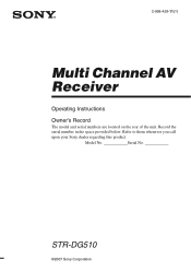
2-898-429-11(1) Multi Channel AV Receiver Operating Instructions Owner's Record The model and serial numbers are located on the rear of the unit. Model No. Serial No. STR-DG510 ©2007 Sony Corporation Record the serial number in the space provided below. Refer to them whenever you call upon your Sony dealer regarding this product.
2-898-429-11(1) Multi Channel AV Receiver Operating Instructions Owner's Record The model and serial numbers are located on the rear of the unit. Model No. Serial No. STR-DG510 ©2007 Sony Corporation Record the serial number in the space provided below. Refer to them whenever you call upon your Sony dealer regarding this product.

Operating Instructions
Page 2
This symbol is connected. - Install this equipment does cause harmful interference to radio or television reception, which the receiver is intended to alert the user to Article 820-40 of the NEC that provides guidelines for proper grounding and, in particular...ground shall be determined by one or more of the following measures: - For customers in cabinet. Reorient or relocate the receiving antenna. - Increase the separation between the equipment and receiver. - Connect the equipment into an outlet on , the user is provided to call CATV system installer's attention to ...
This symbol is connected. - Install this equipment does cause harmful interference to radio or television reception, which the receiver is intended to alert the user to Article 820-40 of the NEC that provides guidelines for proper grounding and, in particular...ground shall be determined by one or more of the following measures: - For customers in cabinet. Reorient or relocate the receiving antenna. - Increase the separation between the equipment and receiver. - Connect the equipment into an outlet on , the user is provided to call CATV system installer's attention to ...

Operating Instructions
Page 3
... in this manual describe the controls on the remote. The recycling of this manual, models of the front panel. This receiver incorporates Dolby* Digital and Pro Logic Surround and the DTS** Digital Surround System. * Manufactured under license from Dolby Laboratories.... For more detailed information about recycling of materials will help to the applicable collection point for model STR-DG510. "Dolby", "Pro Logic" and the double-D symbol are trademarks of Dolby Laboratories. ** "DTS" and "DTS Digital Surround" are ...
... in this manual describe the controls on the remote. The recycling of this manual, models of the front panel. This receiver incorporates Dolby* Digital and Pro Logic Surround and the DTS** Digital Surround System. * Manufactured under license from Dolby Laboratories.... For more detailed information about recycling of materials will help to the applicable collection point for model STR-DG510. "Dolby", "Pro Logic" and the double-D symbol are trademarks of Dolby Laboratories. ** "DTS" and "DTS Digital Surround" are ...

Operating Instructions
Page 4
Note for the supplied remote (RM-AAU013) The VIDEO 3 button on the remote is not available for receiver operation. 4GB
Note for the supplied remote (RM-AAU013) The VIDEO 3 button on the remote is not available for receiver operation. 4GB

Operating Instructions
Page 5
... (INPUT MODE 58 Naming inputs 59 Changing the display 59 Using the Sleep Timer 60 Recording using the receiver 60 Using the Remote Changing button assignments 61 Additional Information Glossary 62 Precautions 63 Troubleshooting 64 Specifications 67 Index...15 3a: Connecting the audio components ........ 16 3b: Connecting the video components ........ 17 4: Connecting the antennas (aerials 25 5: Preparing the receiver and the remote..... 26 6: Selecting the speaker system 27 7: Calibrating the appropriate settings automatically (AUTO CALIBRATION 28 8: Adjusting the speaker levels ...
... (INPUT MODE 58 Naming inputs 59 Changing the display 59 Using the Sleep Timer 60 Recording using the receiver 60 Using the Remote Changing button assignments 61 Additional Information Glossary 62 Precautions 63 Troubleshooting 64 Specifications 67 Index...15 3a: Connecting the audio components ........ 16 3b: Connecting the video components ........ 17 4: Connecting the antennas (aerials 25 5: Preparing the receiver and the remote..... 26 6: Selecting the speaker system 27 7: Calibrating the appropriate settings automatically (AUTO CALIBRATION 28 8: Adjusting the speaker levels ...

Operating Instructions
Page 6
... adjust the volume level of selectable items appears here (page 8). Press to listen to activate the Auto Calibration function (page 29). D Remote sensor Receives signals from remote commander. C Display The current status of the selected component or a list of all speakers at the same time (page 32, 33..., 34, 35). Press to high quality analog sound (page 51). Press to turn the receiver on (on the display (page 57, 59). MOVIE MUSIC AUTO CAL DIRECT qf qd qs qa q; 98 Name Function A ?/1 Press to select a sound...
... adjust the volume level of selectable items appears here (page 8). Press to listen to activate the Auto Calibration function (page 29). D Remote sensor Receives signals from remote commander. C Display The current status of the selected component or a list of all speakers at the same time (page 32, 33..., 34, 35). Press to high quality analog sound (page 51). Press to turn the receiver on (on the display (page 57, 59). MOVIE MUSIC AUTO CAL DIRECT qf qd qs qa q; 98 Name Function A ?/1 Press to select a sound...

Operating Instructions
Page 7
M AUTO CAL MIC jack Connects to headphones (page 64). 7GB N PHONES jack Connects to the supplied optimizer microphone for the Auto Calibration function (page 28). TUNING MODE TUNING +/- Getting Started Name Function L MEMORY/ ENTER Press to operate the tuner (FM/AM) (page 52).
M AUTO CAL MIC jack Connects to headphones (page 64). 7GB N PHONES jack Connects to the supplied optimizer microphone for the Auto Calibration function (page 28). TUNING MODE TUNING +/- Getting Started Name Function L MEMORY/ ENTER Press to operate the tuner (FM/AM) (page 52).

Operating Instructions
Page 8
...and surround channel signals. However, "UNLOCK" appears on the display 12 34 5 67 SW LFE SP A ; "OPT" also lights up when the receiver applies Pro Logic processing to 2 channel signals in order to "YES" (page 42) and the audio signal is output from the SUB WOOFER jack....When playing a Dolby Digital format disc, be sure that you select a sound field using the A.F.D. PLII F OPT G DTS qa q; Lights up when the receiver is decoding Dolby Digital signals. Name E ; PLII" lights up according to "AUTO IN" and the source signal is a digital signal being reproduced. However, these...
...and surround channel signals. However, "UNLOCK" appears on the display 12 34 5 67 SW LFE SP A ; "OPT" also lights up when the receiver applies Pro Logic processing to 2 channel signals in order to "YES" (page 42) and the audio signal is output from the SUB WOOFER jack....When playing a Dolby Digital format disc, be sure that you select a sound field using the A.F.D. PLII F OPT G DTS qa q; Lights up when the receiver is decoding Dolby Digital signals. Name E ; PLII" lights up according to "AUTO IN" and the source signal is a digital signal being reproduced. However, these...

Operating Instructions
Page 9
Lights up when dynamic range compression is activated (page 37). Lights up when using the receiver to tune in radio stations (page 52), etc. Note "RDS" appears for models of area code CEL, CEK only. For details on... or the surround components obtained by Pro Logic processing) Example: Recording format (Front/ Surround): 3/2.1 Output channel: When surround speakers are set to show how the receiver downmixes the source sound (based on the speaker settings). Getting Started Name H MEMORY I Tuner indicators J Preset station indicators K D.RANGE L COAX M Playback channel indicators L R...
Lights up when dynamic range compression is activated (page 37). Lights up when using the receiver to tune in radio stations (page 52), etc. Note "RDS" appears for models of area code CEL, CEK only. For details on... or the surround components obtained by Pro Logic processing) Example: Recording format (Front/ Surround): 3/2.1 Output channel: When surround speakers are set to show how the receiver downmixes the source sound (based on the speaker settings). Getting Started Name H MEMORY I Tuner indicators J Preset station indicators K D.RANGE L COAX M Playback channel indicators L R...

Operating Instructions
Page 10
CENTER SURROUND L FRONT A L + - + - HDMI IN/ OUT jacks* Connects to a DVD VIDEO player, TV, or a Blue INPUT/ satellite tuner. B COMPONENT VIDEO INPUT/ OUTPUT section Green (Y) COMPONENT Connects to a DVD player, etc. R R SPEAKERS RL FRONT B SPEAKERS 65 4 3 A DIGITAL INPUT/OUTPUT section OPTICAL Connects to a TV or a projector (page 18). The image and the sound are output to a DVD IN jacks player, etc. You (PB/CB) OUTPUT can enjoy high jacks* quality image (page Red (PR/CR) 20, 21, 23). The COAXIAL jack COAXIAL IN provides a better jack ...
CENTER SURROUND L FRONT A L + - + - HDMI IN/ OUT jacks* Connects to a DVD VIDEO player, TV, or a Blue INPUT/ satellite tuner. B COMPONENT VIDEO INPUT/ OUTPUT section Green (Y) COMPONENT Connects to a DVD player, etc. R R SPEAKERS RL FRONT B SPEAKERS 65 4 3 A DIGITAL INPUT/OUTPUT section OPTICAL Connects to a TV or a projector (page 18). The image and the sound are output to a DVD IN jacks player, etc. You (PB/CB) OUTPUT can enjoy high jacks* quality image (page Red (PR/CR) 20, 21, 23). The COAXIAL jack COAXIAL IN provides a better jack ...

Operating Instructions
Page 11
...TUNING + m H M TV X x 4 5 6 7 8 9 q; REPLAY ADVANCE PRESET + .< > < TUNING - ql qk qj qh qg qf qd TV INPUT AUTO TV ?/1 SLEEP CAL AV ?/1 ?/1 SYSTEM STANDBY VIDEO 1 VIDEO 2 VIDEO 3 DVD SAT TV SA-CD/CD TUNER 1 2 3 2CH A.F.D. TV CH + PRESET - qa qs continued 11GB Remote commander You can watch... AM ANTENNA terminals Connects to the AM loop antenna (aerial) supplied with this receiver (page 25). * You can use the supplied remote RM-AAU013 to operate the receiver and to control the Sony audio/video components that the remote is assigned to operate (page 61). Getting ...
...TUNING + m H M TV X x 4 5 6 7 8 9 q; REPLAY ADVANCE PRESET + .< > < TUNING - ql qk qj qh qg qf qd TV INPUT AUTO TV ?/1 SLEEP CAL AV ?/1 ?/1 SYSTEM STANDBY VIDEO 1 VIDEO 2 VIDEO 3 DVD SAT TV SA-CD/CD TUNER 1 2 3 2CH A.F.D. TV CH + PRESET - qa qs continued 11GB Remote commander You can watch... AM ANTENNA terminals Connects to the AM loop antenna (aerial) supplied with this receiver (page 25). * You can use the supplied remote RM-AAU013 to operate the receiver and to control the Sony audio/video components that the remote is assigned to operate (page 61). Getting ...

Operating Instructions
Page 12
... you press any of all components, press ?/1 and AV ?/1 (A) at the same time (SYSTEM STANDBY). When you want to use. Press to control Sony components as follows. Press to adjust the volume level of the input buttons, the receiver turns on. Press to replay the previous scene or ...page 61. The buttons are factory assigned to activate the muting function. Button Assigned Sony component VIDEO 1 VCR (VTR mode 3) VIDEO 2 VCR (VTR mode 2) VIDEO 3 Not assigned DVD DVD player SAT Digital Satellite Receiver TV TV SA-CD/CD Super Audio CD/ CD player TUNER Built-in "...
... you press any of all components, press ?/1 and AV ?/1 (A) at the same time (SYSTEM STANDBY). When you want to use. Press to control Sony components as follows. Press to adjust the volume level of the input buttons, the receiver turns on. Press to replay the previous scene or ...page 61. The buttons are factory assigned to activate the muting function. Button Assigned Sony component VIDEO 1 VCR (VTR mode 3) VIDEO 2 VCR (VTR mode 2) VIDEO 3 Not assigned DVD DVD player SAT Digital Satellite Receiver TV TV SA-CD/CD Super Audio CD/ CD player TUNER Built-in "...

Operating Instructions
Page 13
... on the TV screen. Press to display options applicable to select the settings. and TV (M) at the same time to display the menu of the receiver, VCR, satellite tuner, CD player, DVD player or blu-ray disc player. Press to display the TV's menu. Press MENU and TV (M) at the same...
... on the TV screen. Press to display options applicable to select the settings. and TV (M) at the same time to display the menu of the receiver, VCR, satellite tuner, CD player, DVD player or blu-ray disc player. Press to display the TV's menu. Press MENU and TV (M) at the same...

Operating Instructions
Page 14
Press TV INPUT and TV (M) at the same time to activate the Sleep Timer function and the duration which the receiver turns off automatically. Press to select the input signal (TV input or video input). Press the numeric buttons and TV (M) at the same time... when you press the incorrect numeric button. select track numbers of the VCR or satellite tuner. Press 0/ 10 to serve as references when operating the receiver. Notes • Some functions explained in this section may operate differently than described. • The VIDEO 3 button on the model. • The above ...
Press TV INPUT and TV (M) at the same time to activate the Sleep Timer function and the duration which the receiver turns off automatically. Press to select the input signal (TV input or video input). Press the numeric buttons and TV (M) at the same time... when you press the incorrect numeric button. select track numbers of the VCR or satellite tuner. Press 0/ 10 to serve as references when operating the receiver. Notes • Some functions explained in this section may operate differently than described. • The VIDEO 3 button on the model. • The above ...

Operating Instructions
Page 15
... you want to the SPEAKERS FRONT B terminals. If the auto standby function is set to on, it turns to standby mode automatically based on the receiver (page 27). Getting Started 2: Connecting speakers F C A A B SPEAKERS FRONT B terminalsa) IN VIDEO 2 /BD IN OUT HDMI Y PB/CB PR/CR VIDEO IN VIDEO IN VIDEO OUT...
... you want to the SPEAKERS FRONT B terminals. If the auto standby function is set to on, it turns to standby mode automatically based on the receiver (page 27). Getting Started 2: Connecting speakers F C A A B SPEAKERS FRONT B terminalsa) IN VIDEO 2 /BD IN OUT HDMI Y PB/CB PR/CR VIDEO IN VIDEO IN VIDEO OUT...

Operating Instructions
Page 16
Super Audio CD player/CD player A OPTICAL SAT IN DVD IN VIDEO 2 /BD IN OUT HDMI Y PB/CB VIDEO 2/ BD IN DVD IN COAXIAL DIGITAL AM VIDEO IN VIDEO IN VIDEO OUT VIDEO IN VIDEO OUT SAT DVD VIDEO 1 MONITOR PR/CR SAT IN DVD IN MONITOR OUT COMPONENT VIDEO ANTENNA L L L AUDIO OUT R R R AUDIO IN AUDIO IN AUDIO IN AUDIO OUT AUDIO IN SUB SA-CD/CD TV SAT VIDEO 1 WOOFER + - R R SPEAKERS RL FRONT B SPEAKERS A Audio cord (not supplied) 16GB 3a: Connecting the audio components Connecting a Super Audio CD/ CD player The following illustration shows how to "3b: Connecting the video ...
Super Audio CD player/CD player A OPTICAL SAT IN DVD IN VIDEO 2 /BD IN OUT HDMI Y PB/CB VIDEO 2/ BD IN DVD IN COAXIAL DIGITAL AM VIDEO IN VIDEO IN VIDEO OUT VIDEO IN VIDEO OUT SAT DVD VIDEO 1 MONITOR PR/CR SAT IN DVD IN MONITOR OUT COMPONENT VIDEO ANTENNA L L L AUDIO OUT R R R AUDIO IN AUDIO IN AUDIO IN AUDIO OUT AUDIO IN SUB SA-CD/CD TV SAT VIDEO 1 WOOFER + - R R SPEAKERS RL FRONT B SPEAKERS A Audio cord (not supplied) 16GB 3a: Connecting the audio components Connecting a Super Audio CD/ CD player The following illustration shows how to "3b: Connecting the video ...

Operating Instructions
Page 17
Refer to "4: Connecting the antennas (aerials)" (page 25). INPUT jack COMPONENT HDMI VIDEO VIDEO Receiver MONITOR OUT, HDMI OUT jack COMPONENT HDMI VIDEO VIDEO ?/1 SPEAKERS (OFF/A/B) AUTO CAL MIC PHONES DISPLAY INPUT MODE INPUT SELECTOR MASTER VOLUME ... connected The image quality depends on your components. TV, etc. Component to be connected" below for the pages which describe how to this receiver. Getting Started 3b: Connecting the video components How to connect your components This section describes how to connect your video components to connect each...
Refer to "4: Connecting the antennas (aerials)" (page 25). INPUT jack COMPONENT HDMI VIDEO VIDEO Receiver MONITOR OUT, HDMI OUT jack COMPONENT HDMI VIDEO VIDEO ?/1 SPEAKERS (OFF/A/B) AUTO CAL MIC PHONES DISPLAY INPUT MODE INPUT SELECTOR MASTER VOLUME ... connected The image quality depends on your components. TV, etc. Component to be connected" below for the pages which describe how to this receiver. Getting Started 3b: Connecting the video components How to connect your components This section describes how to connect your video components to connect each...

Operating Instructions
Page 18
... video and audio signals in digital format. R R SPEAKERS RL FRONT B SPEAKERS A Coaxial digital cord (not supplied) B HDMI cable (not supplied) We recommend that you use a Sony HDMI cable. CENTER SURROUND L FRONT A L + - + - It is the abbreviated name for HighDefinition Multimedia Interface.
... video and audio signals in digital format. R R SPEAKERS RL FRONT B SPEAKERS A Coaxial digital cord (not supplied) B HDMI cable (not supplied) We recommend that you use a Sony HDMI cable. CENTER SURROUND L FRONT A L + - + - It is the abbreviated name for HighDefinition Multimedia Interface.

Operating Instructions
Page 19
... on HDMI connections • The sound is poor or the sound does not come out of a component connected via the HDMI cable. • This receiver may not be able to transfer video or audio signals with 32 kHz, 44.1 kHz, 48 kHz, and 96 kHz sampling frequencies. 19GB For details...being output to control your blu-ray disc player. To output the sound from the TV speaker only when a playback component and this receiver, as well as this receiver and the TV are compatible with certain types of components. • Refer to the operating instructions of the multi channel surround sound, be...
... on HDMI connections • The sound is poor or the sound does not come out of a component connected via the HDMI cable. • This receiver may not be able to transfer video or audio signals with 32 kHz, 44.1 kHz, 48 kHz, and 96 kHz sampling frequencies. 19GB For details...being output to control your blu-ray disc player. To output the sound from the TV speaker only when a playback component and this receiver, as well as this receiver and the TV are compatible with certain types of components. • Refer to the operating instructions of the multi channel surround sound, be...

Operating Instructions
Page 20
... signals of your components. CENTER SURROUND L FRONT A L + - + - connect the audio output jacks of the TV from a video component connected to this receiver can be displayed on a TV screen. Connect audio and video cords according to turn off or mute the TV's volume. R R SPEAKERS RL FRONT B SPEAKERS ...or projector. • To output the sound of the TV to connect all the cords. Connecting a TV The image from the speakers connected to the receiver, be sure to: - Audio signals TV Video signals A B C OPTICAL SAT IN DVD IN VIDEO 2 /BD IN OUT HDMI Y PB/CB VIDEO...
... signals of your components. CENTER SURROUND L FRONT A L + - + - connect the audio output jacks of the TV from a video component connected to this receiver can be displayed on a TV screen. Connect audio and video cords according to turn off or mute the TV's volume. R R SPEAKERS RL FRONT B SPEAKERS ...or projector. • To output the sound of the TV to connect all the cords. Connecting a TV The image from the speakers connected to the receiver, be sure to: - Audio signals TV Video signals A B C OPTICAL SAT IN DVD IN VIDEO 2 /BD IN OUT HDMI Y PB/CB VIDEO...
