Service Manual
Page 1
... optical pick-up Name KSM-213CDP KSS-213C TC Model Name Using Similar Mechanism CFD-S01 Section Tape Transport Mechanism Type MF-S01 SPECIFICATIONS CD player section System Compact disc digital audio system Laser diode properties Emission duration: Continuous Laser output: Less than 44.6 µW (This output is the value measured at 4 Ω, 10% harmonic distortion) Power requirements For CD radio cassette-corder: 120 V AC, 60 Hz (CND, E92, MX, TW...
... optical pick-up Name KSM-213CDP KSS-213C TC Model Name Using Similar Mechanism CFD-S01 Section Tape Transport Mechanism Type MF-S01 SPECIFICATIONS CD player section System Compact disc digital audio system Laser diode properties Emission duration: Continuous Laser output: Less than 44.6 µW (This output is the value measured at 4 Ω, 10% harmonic distortion) Power requirements For CD radio cassette-corder: 120 V AC, 60 Hz (CND, E92, MX, TW...
Service Manual
Page 2
... LES SUPPLÉMENTS PUBLIÉS PAR SONY. Therefore, when checking the laser diode emission, observe from the objective lens. projecting parts) Mass Approx. 2.6 kg (incl. batteries) Supplied accessory AC power cord (1) Remote control (1) Design and specifications are subject to electrostatic breakdown and also use the procedure in the printed matter which mates DVD recorded material on the conductor when soldering or unsoldering...
... LES SUPPLÉMENTS PUBLIÉS PAR SONY. Therefore, when checking the laser diode emission, observe from the objective lens. projecting parts) Mass Approx. 2.6 kg (incl. batteries) Supplied accessory AC power cord (1) Remote control (1) Design and specifications are subject to electrostatic breakdown and also use the procedure in the printed matter which mates DVD recorded material on the conductor when soldering or unsoldering...
Service Manual
Page 3
GENERAL 5 3. DISASSEMBLY 3-1. Main Board 8 3-4. ELECTRICAL ADJUSTMENTS Tape Section 13 Tuner Section 14 CD Section 16 6. BD83S Section 20 6-5. Schematic Diagram - Schematic Diagram - Main Section (1/3 23 6-8. Schematic Diagram - TC Section 27 6-12. CD Mechanism Section 44 8. CD Block Assy 8 3-5. Power Board 12 4. Circuit Boards Location 19 6-4. BD83S Section 21 6-6. Printed Wiring Board - TC Section 26 6-11. Printed Wiring Boards - Schematic Diagram - Power Supply Section 30 6-15. Power Supply Section 31 7. Front Cabinet...
GENERAL 5 3. DISASSEMBLY 3-1. Main Board 8 3-4. ELECTRICAL ADJUSTMENTS Tape Section 13 Tuner Section 14 CD Section 16 6. BD83S Section 20 6-5. Schematic Diagram - Schematic Diagram - Main Section (1/3 23 6-8. Schematic Diagram - TC Section 27 6-12. CD Mechanism Section 44 8. CD Block Assy 8 3-5. Power Board 12 4. Circuit Boards Location 19 6-4. BD83S Section 21 6-6. Printed Wiring Board - TC Section 26 6-11. Printed Wiring Boards - Schematic Diagram - Power Supply Section 30 6-15. Power Supply Section 31 7. Front Cabinet...

Service Manual
Page 4
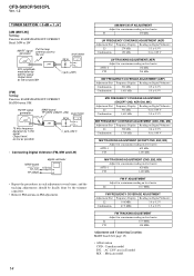
... ON REPAIRING On repairing CD section, playing a disc without the lid (CD), use Chuck Plate Jig. • Code number of Chuck Plate Jig: X-4918-255-1 LASER DIODE AND FOCUS SEARCH OPERATION CHECK 1. Turn ON the [OPERATE] button and press [CD] button to CD position. 2. as following figure. 4. Objective lens moves up is no emission, Auto Power Control circuit or Optical Pick-up and down three times for focus search. SW2 4 Open the CD...
... ON REPAIRING On repairing CD section, playing a disc without the lid (CD), use Chuck Plate Jig. • Code number of Chuck Plate Jig: X-4918-255-1 LASER DIODE AND FOCUS SEARCH OPERATION CHECK 1. Turn ON the [OPERATE] button and press [CD] button to CD position. 2. as following figure. 4. Objective lens moves up is no emission, Auto Power Control circuit or Optical Pick-up and down three times for focus search. SW2 4 Open the CD...

Service Manual
Page 5
... you need to open the CD compartment or turn on the CD compartment. The player plays all the files on the remote) qa. After changing the tuning interval, you . Make sure there is no folder, "ROOT" appears in the display. ** If the playing time is wound to the end, press xZ qs to the sound Locate a point while observing the display Remove the CD Press u 9. Recording on a tape Use buttons...
... you need to open the CD compartment or turn on the CD compartment. The player plays all the files on the remote) qa. After changing the tuning interval, you . Make sure there is no folder, "ROOT" appears in the display. ** If the playing time is wound to the end, press xZ qs to the sound Locate a point while observing the display Remove the CD Press u 9. Recording on a tape Use buttons...

Service Manual
Page 13
... following parts with a denatured-alcohol-moistened swab : record/playback head pinch roller erase head rubber belts capstan idlers 2. Do not use a magnetized screwdriver for tape speed adjustment Tape Speed Adjustment Procedure: Mode: playback test tape WS-48A (3 kHz, 0 dB) set digital frequency counter 32 Ω i jack (J321) Adjust so that at the end of tape winding are between 2,910 to the erase head.) 3. Adjustment Location: Tape speed adjustment control inside...
... following parts with a denatured-alcohol-moistened swab : record/playback head pinch roller erase head rubber belts capstan idlers 2. Do not use a magnetized screwdriver for tape speed adjustment Tape Speed Adjustment Procedure: Mode: playback test tape WS-48A (3 kHz, 0 dB) set digital frequency counter 32 Ω i jack (J321) Adjust so that at the end of tape winding are between 2,910 to the erase head.) 3. Adjustment Location: Tape speed adjustment control inside...
Service Manual
Page 14
... generator Put the loop antenna close to the set 30% amplitude modulation by 400 Hz signal Output level: as low as possible i jack (J321) • Connecting Digital Voltmeter (FM, MW and LW) digital voltmeter MAIN board TP (VT) TP (GND) 100 k Ω • Repeat the procedures in E model MX : Mexican model 14 i jack (J321) [FM] Setting: Function: RADIO/BAND/AUTO PRESET BAND button: FM FM RF...
... generator Put the loop antenna close to the set 30% amplitude modulation by 400 Hz signal Output level: as low as possible i jack (J321) • Connecting Digital Voltmeter (FM, MW and LW) digital voltmeter MAIN board TP (VT) TP (GND) 100 k Ω • Repeat the procedures in E model MX : Mexican model 14 i jack (J321) [FM] Setting: Function: RADIO/BAND/AUTO PRESET BAND button: FM FM RF...
Service Manual
Page 16
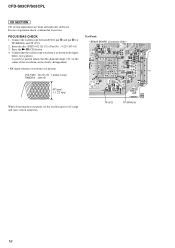
...Part No. : 4-225-203-01) 3. Confirm that the oscilloscope waveform is as shown in the figure below. (eye pattern) A good eye pattern means that focus bias. Press the N X (CD) button. 4. FOCUS BIAS CHECK 1. and pin th (or TP (RFAC0) and TP (VC)). 2. CFD-S03CP/S03CPL CD SECTION CD section adjustments are done automatically in this set... Side) - In case of operation check, confirm that the diamond shape ( ) in the center of the waveform can be clearly distinguished. • RF signal reference waveform (eye pattern) VOLT/DIV : 50 mV (10 : 1 probe in use) TIME/DIV : 500 nS RF level...
...Part No. : 4-225-203-01) 3. Confirm that the oscilloscope waveform is as shown in the figure below. (eye pattern) A good eye pattern means that focus bias. Press the N X (CD) button. 4. FOCUS BIAS CHECK 1. and pin th (or TP (RFAC0) and TP (VC)). 2. CFD-S03CP/S03CPL CD SECTION CD section adjustments are done automatically in this set... Side) - In case of operation check, confirm that the diamond shape ( ) in the center of the waveform can be clearly distinguished. • RF signal reference waveform (eye pattern) VOLT/DIV : 50 mV (10 : 1 probe in use) TIME/DIV : 500 nS RF level...

Service Manual
Page 17
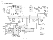
... MOTOR DRIVE SPINDLE MOTOR DRIVE CH3INF 23 CH3INR 22 CH4IN 24 OPOUT 27 SLED/SPINDLE MOTOR DRIVER, OPIN+ 2 TRACKING/FOCUS VREF 26 VC COIL DRIVER IC402 18 LID-OPEN 36 23 38 37 CD 6V CD 3.3V +3.3V REC/PB POWER CONTROL Q957-959,D957 6V (TAPE) RADIO +B X201 16.93MHz SYSTEM CONTROLLER IC801 ...AUDIO+6V REG Q955,D953 POWER SWITCH Q952,953 VDD POWER SWITCH Q951 U-COM (VDD) T901 POWER TRANSFORMER D901 - 904 F902 RECT J901 AC IN BATT DRY BATTERY SIZE "D" (IEC DESIGNATION R20) 6PCS, 9V CFD-S03CP/S03CPL 17 17 F+ F- SP+ SP- IC202 CD3.3V REG-CHK I-CD-CTL V-CHECK BAT-CHK-H O-POWER...
... MOTOR DRIVE SPINDLE MOTOR DRIVE CH3INF 23 CH3INR 22 CH4IN 24 OPOUT 27 SLED/SPINDLE MOTOR DRIVER, OPIN+ 2 TRACKING/FOCUS VREF 26 VC COIL DRIVER IC402 18 LID-OPEN 36 23 38 37 CD 6V CD 3.3V +3.3V REC/PB POWER CONTROL Q957-959,D957 6V (TAPE) RADIO +B X201 16.93MHz SYSTEM CONTROLLER IC801 ...AUDIO+6V REG Q955,D953 POWER SWITCH Q952,953 VDD POWER SWITCH Q951 U-COM (VDD) T901 POWER TRANSFORMER D901 - 904 F902 RECT J901 AC IN BATT DRY BATTERY SIZE "D" (IEC DESIGNATION R20) 6PCS, 9V CFD-S03CP/S03CPL 17 17 F+ F- SP+ SP- IC202 CD3.3V REG-CHK I-CD-CTL V-CHECK BAT-CHK-H O-POWER...
Service Manual
Page 18
... RADIO L R.LO 18 LINE 17 R-CH TAPE 15 22 16 TU_IN_R REC BIAS OSC Q301 IC302 ELECTRONIC VOLUME L-IN 8 VOL AMP L-OUT 7 LOGIC 54 CLK DATA POWER AMP IC303 6 2 R-CH MEGA BASS SWITCH Q122 MUTE Q124 U-COM (VDD) LEVEL DETECT D323 D322 TAPE PLAY DETECT Q808 J321 i 9V (SW) SP101 SPEAKER (L-CH) SP201 SPEAKER (R-CH) SW1 (TAPE PLAY) ANT1-1,CT3 MW TRACKING ANT1-2,CT5 LW TRACKING...
... RADIO L R.LO 18 LINE 17 R-CH TAPE 15 22 16 TU_IN_R REC BIAS OSC Q301 IC302 ELECTRONIC VOLUME L-IN 8 VOL AMP L-OUT 7 LOGIC 54 CLK DATA POWER AMP IC303 6 2 R-CH MEGA BASS SWITCH Q122 MUTE Q124 U-COM (VDD) LEVEL DETECT D323 D322 TAPE PLAY DETECT Q808 J321 i 9V (SW) SP101 SPEAKER (L-CH) SP201 SPEAKER (R-CH) SW1 (TAPE PLAY) ANT1-1,CT3 MW TRACKING ANT1-2,CT5 LW TRACKING...

Service Manual
Page 19
... face side: (Conductor Side) Parts face side: (Component Side) Parts on the parts face side seen from the pattern face are indicated. Voltage variations may be noted due to normal production tolerances. • Circled numbers refer to normal production tolerances. • Waveforms are omitted. CIRCUIT BOARDS LOCATION HEADPHONE board POWER board BD83S board BATTERY-1 board KEY-1 board PANEL...
... face side: (Conductor Side) Parts face side: (Component Side) Parts on the parts face side seen from the pattern face are indicated. Voltage variations may be noted due to normal production tolerances. • Circled numbers refer to normal production tolerances. • Waveforms are omitted. CIRCUIT BOARDS LOCATION HEADPHONE board POWER board BD83S board BATTERY-1 board KEY-1 board PANEL...

Service Manual
Page 28
... S403 R402 S403 MEGA BASS R401 D406 S401 1-869-161- S401 z/POWER (EXCEPT AEP,UK,CET,IT) z/OPERATE (AEP,UK,CET,IT) D406 OPR/BATT CN403 4 2 3 1 11 (11) E F 13 G 24 CN421 R424 R423 FFC412 R422 R421 S421 FFC411 S411 11 1-869-162- (11) S424 S422 H S423 11 1-849-163- (11) CD RADIO/BAND/ TAPE AUTO PRESET VOLUME I CFD-S03CP/S03CPL 28...
... S403 R402 S403 MEGA BASS R401 D406 S401 1-869-161- S401 z/POWER (EXCEPT AEP,UK,CET,IT) z/OPERATE (AEP,UK,CET,IT) D406 OPR/BATT CN403 4 2 3 1 11 (11) E F 13 G 24 CN421 R424 R423 FFC412 R422 R421 S421 FFC411 S411 11 1-869-162- (11) S424 S422 H S423 11 1-849-163- (11) CD RADIO/BAND/ TAPE AUTO PRESET VOLUME I CFD-S03CP/S03CPL 28...

Service Manual
Page 34
... servo drive signal (+) output to the coil/motor driver 46 FRDR O Focus servo drive signal (-) output to the system controller 21 WFCK - Not used 33 FOK - Not used 25 C2PO - Ground terminal 37 MIRR - CFD-S03CP/S03CPL • IC PIN DESCRIPTIONS • IC201 CXD3014A-201R (RF AMP, SYSTEM SERVO PROCESSOR, DIGITAL SIGNAL PROCESSOR) (BD83S BOARD) Pin No. Not used 32 DFCT - Power supply...
... servo drive signal (+) output to the coil/motor driver 46 FRDR O Focus servo drive signal (-) output to the system controller 21 WFCK - Not used 33 FOK - Not used 25 C2PO - Ground terminal 37 MIRR - CFD-S03CP/S03CPL • IC PIN DESCRIPTIONS • IC201 CXD3014A-201R (RF AMP, SYSTEM SERVO PROCESSOR, DIGITAL SIGNAL PROCESSOR) (BD83S BOARD) Pin No. Not used 32 DFCT - Power supply...

Service Manual
Page 35
... - Ground terminal I Test terminal Normally: fixed at "L" I CD serial data input from the system controller I /O Pin Description - Power supply terminal (+3.3V) I Asymmetry circuit constant current input terminal I Playback EFM asymmetry comparator voltage input terminal O Playback EFM full-swing output terminal O Charge pump output terminal for broad-band EFM PLL I Filter input terminal for master PLL O Charge pump output terminal for broad-band EFM PLL...
... - Ground terminal I Test terminal Normally: fixed at "L" I CD serial data input from the system controller I /O Pin Description - Power supply terminal (+3.3V) I Asymmetry circuit constant current input terminal I Playback EFM asymmetry comparator voltage input terminal O Playback EFM full-swing output terminal O Charge pump output terminal for broad-band EFM PLL I Filter input terminal for master PLL O Charge pump output terminal for broad-band EFM PLL...

Service Manual
Page 37
... CLK O Volume command serial transfer clock output 35 AGND - Not used (Open) 15 VCC - Ground 17 M-BASS O MEGA BASS control signal output 18 LID-OPEN I CD door open/close switch input L: Close 19 O-TU-CE O Tuner PLL chip enable signal output 20 O-TU-CLK O Tuner PLL serial transfer clock output 21 O-TU-DATA O Tuner PLL serial data output 22 I-TU-COUNT I Tuner PLL serial data input 23 O-CD-CLT O CD power control signal output H: CD ON 24 TAPE PLAY I Tape play switch signal input 25 TAPE REC I Tape record switch signal...
... CLK O Volume command serial transfer clock output 35 AGND - Not used (Open) 15 VCC - Ground 17 M-BASS O MEGA BASS control signal output 18 LID-OPEN I CD door open/close switch input L: Close 19 O-TU-CE O Tuner PLL chip enable signal output 20 O-TU-CLK O Tuner PLL serial transfer clock output 21 O-TU-DATA O Tuner PLL serial data output 22 I-TU-COUNT I Tuner PLL serial data input 23 O-CD-CLT O CD power control signal output H: CD ON 24 TAPE PLAY I Tape play switch signal input 25 TAPE REC I Tape record switch signal...

Service Manual
Page 38
Not used (Open) 38 Power supply (+3.3 V) - Ground O LCD drive segment signal output - Ground O Main system oscillation output (4.19 MHz) I System reset signal input O Audio CD mode control signal output - Not used (Open) O LCD drive common signal output O LCD drive segment signal output O LCD drive segment signal output - Not used (Open) O Audio tape mode control signal output - Power supply (+3.3 V) - CFD-S03CP/S03CPL Pin No. 50 51 52 53 54 55 56 57 58 59 to 62 63 64 65 66 67 to 89...
Not used (Open) 38 Power supply (+3.3 V) - Ground O LCD drive segment signal output - Ground O Main system oscillation output (4.19 MHz) I System reset signal input O Audio CD mode control signal output - Not used (Open) O LCD drive common signal output O LCD drive segment signal output O LCD drive segment signal output - Not used (Open) O Audio tape mode control signal output - Power supply (+3.3 V) - CFD-S03CP/S03CPL Pin No. 50 51 52 53 54 55 56 57 58 59 to 62 63 64 65 66 67 to 89...
Service Manual
Page 39
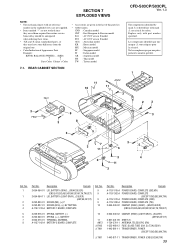
...,CET) 2-654-054-11 LID, BATTERY (LIGHT GRAY)...(SILVER) (AEP,UK,CET,IT) 3-252-833-01 SCREW (M3), (+) P 3-252-827-01 SCREW (B2.6), (+) BV TAPPING A-1157-013-A BATTERY-1 BOARD, COMPLETE Ref. No. 9 9 9 9 10 Part No. REAR CABINET SECTION CFD-S03CP/S03CPL Ver. 1.3 The components identified by mark 0 or dotted line with part number specified. Les composants identifié...
...,CET) 2-654-054-11 LID, BATTERY (LIGHT GRAY)...(SILVER) (AEP,UK,CET,IT) 3-252-833-01 SCREW (M3), (+) P 3-252-827-01 SCREW (B2.6), (+) BV TAPPING A-1157-013-A BATTERY-1 BOARD, COMPLETE Ref. No. 9 9 9 9 10 Part No. REAR CABINET SECTION CFD-S03CP/S03CPL Ver. 1.3 The components identified by mark 0 or dotted line with part number specified. Les composants identifié...
Service Manual
Page 53
...,E92,MX ACCESSORIES 0 1-590-342-12 CORD, POWER (E92,MX) 0 1-769-412-22 CORD, POWER (AEP,CET,E41,IT,SP,TH) 0 1-770-019-61 ADAPTOR, CONVERSION PLUG (UK) 0 1-776-985-12 CORD, POWER (KR) 0 1-782-126-11 CORD, POWER (CND) 0 1-783-952-21 CORD, POWER (AR) 0 1-827-945-12 CORD, POWER (AUS) 0 1-827-946-21 CORD, POWER (UK) 0 1-829-433-11 CORD, POWER (TW) 2-655-836-11 MANUAL, INSTRUCTION (ENGLISH) (CND...
...,E92,MX ACCESSORIES 0 1-590-342-12 CORD, POWER (E92,MX) 0 1-769-412-22 CORD, POWER (AEP,CET,E41,IT,SP,TH) 0 1-770-019-61 ADAPTOR, CONVERSION PLUG (UK) 0 1-776-985-12 CORD, POWER (KR) 0 1-782-126-11 CORD, POWER (CND) 0 1-783-952-21 CORD, POWER (AR) 0 1-827-945-12 CORD, POWER (AUS) 0 1-827-946-21 CORD, POWER (UK) 0 1-829-433-11 CORD, POWER (TW) 2-655-836-11 MANUAL, INSTRUCTION (ENGLISH) (CND...
Operating Instructions
Page 1
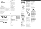
... press the button, the indication changes as a power source for 2 seconds. After changing the tuning interval, you notice an abnormality in the display. Each time you put the extension "mp3" to reset your nearest Sony service station. MPEG Layer-3 audio coding technology and patents licensed from the AC outlet immediately. Replacing batteries With normal use the plug without notice. Should you need to the Compact Disc (CD) standard. batteries) Supplied accessories AC power cord (1) Remote control (1) Design and...
... press the button, the indication changes as a power source for 2 seconds. After changing the tuning interval, you notice an abnormality in the display. Each time you put the extension "mp3" to reset your nearest Sony service station. MPEG Layer-3 audio coding technology and patents licensed from the AC outlet immediately. Replacing batteries With normal use the plug without notice. Should you need to the Compact Disc (CD) standard. batteries) Supplied accessories AC power cord (1) Remote control (1) Design and...
Operating Instructions
Page 2
... record or play tracks/MP3 files repeatedly in the display. Tip The preset radio stations remain in the programed order. Refer servicing to qualified personnel only. • Should any obstacles in the CD player section is not on. • Connect the AC power cord to disassemble the casing. Notes on this function: If the tape length of one . Side A Tab for side A Tab for Compact Disc Digital Audio. Troubleshooting...
... record or play tracks/MP3 files repeatedly in the display. Tip The preset radio stations remain in the programed order. Refer servicing to qualified personnel only. • Should any obstacles in the CD player section is not on. • Connect the AC power cord to disassemble the casing. Notes on this function: If the tape length of one . Side A Tab for side A Tab for Compact Disc Digital Audio. Troubleshooting...


