
Service Manual
Page 1
... x (Digital) CCD-TR516/TR516PK/TR716 CCD-TRV36/TRV36PK/TRV43/TRV46/ - Video camera recorder System Video recording system 2 Rotary heads Helical scanning FM system Audio recording system Rotary heads, FM system Video signal NTSC color, EIA standards Usable cassette 8mm video format cassette CCD-TR315/TR416/TR416PK CCD-TRV16/TRV16PK : standard 8 CCD-TR516/TR516PK/TR716 CCD-TRV36/TRV36PK/TRV43/TRV46/ TRV46PK : Hi8 Recording / Playback...
... x (Digital) CCD-TR516/TR516PK/TR716 CCD-TRV36/TRV36PK/TRV43/TRV46/ - Video camera recorder System Video recording system 2 Rotary heads Helical scanning FM system Audio recording system Rotary heads, FM system Video signal NTSC color, EIA standards Usable cassette 8mm video format cassette CCD-TR315/TR416/TR416PK CCD-TRV16/TRV16PK : standard 8 CCD-TR516/TR516PK/TR716 CCD-TRV36/TRV36PK/TRV43/TRV46/ TRV46PK : Hi8 Recording / Playback...

Service Manual
Page 2
...CES SONT CRITIQUES POUR LA SÉCURITÉ DE FONCTIONNEMENT. Input and output connectors Video output Phono jack, 1 Vp-p, 75 ohms, unbalanced Audio output Monaural, Phone jack... COMPOSANTS QUE PAR DES PIÉCES SONY DONT LES NUMÉROS SONT DONNÉS DANS CE MANUEL OU ...when using the battery pack) During camera recording CCD-TR416/TR416PK/TR516/ TR516PK : 2.4 W CCD-TR315/TR716 : 2.5 W During camera recording using LCD CCD-TRV16/TRV16PK/TRV36/ TRV36PK : 3.1 W CCD-TRV43/TRV46/TRV46PK : 3.2 W Viewfinder CCD-TRV16/TRV16PK/TRV36/ TRV36PK : 2.5 W CCD-TRV43/TRV46/TRV46PK : 2.6 W Operating...
...CES SONT CRITIQUES POUR LA SÉCURITÉ DE FONCTIONNEMENT. Input and output connectors Video output Phono jack, 1 Vp-p, 75 ohms, unbalanced Audio output Monaural, Phone jack... COMPOSANTS QUE PAR DES PIÉCES SONY DONT LES NUMÉROS SONT DONNÉS DANS CE MANUEL OU ...when using the battery pack) During camera recording CCD-TR416/TR416PK/TR516/ TR516PK : 2.4 W CCD-TR315/TR716 : 2.5 W During camera recording using LCD CCD-TRV16/TRV16PK/TRV36/ TRV36PK : 3.1 W CCD-TRV43/TRV46/TRV46PK : 3.2 W Viewfinder CCD-TRV16/TRV16PK/TRV36/ TRV36PK : 2.5 W CCD-TRV43/TRV46/TRV46PK : 2.6 W Operating...

Service Manual
Page 8
... of Display 6 4. Using this manual 1-1 Checking supplied accessories 1-1 Installing and Charging the battery pack 1-1 Inserting a cassette 1-2 Camera recording 1-2 Hints for better Shooting 1-4 Checking the recorded picture 1-4 Playing back a tape 1-5 Searching for the end of the ...the exposure 1-10 Superimposing a title 1-11 Making your camcorder abroad 1-17 Truoble check 1-17 Self-diagnosis display 1-18 Identifying the parts 1-18 Warning Indicators 1-20 2-1. Removal of CCD-TRV36/TRV43/TRV46. Camera/Video 1 Block Diagram 3-5 3-3. Mode Control Block Diagram 3-15...
... of Display 6 4. Using this manual 1-1 Checking supplied accessories 1-1 Installing and Charging the battery pack 1-1 Inserting a cassette 1-2 Camera recording 1-2 Hints for better Shooting 1-4 Checking the recorded picture 1-4 Playing back a tape 1-5 Searching for the end of the ...the exposure 1-10 Superimposing a title 1-11 Making your camcorder abroad 1-17 Truoble check 1-17 Self-diagnosis display 1-18 Identifying the parts 1-18 Warning Indicators 1-20 2-1. Removal of CCD-TRV36/TRV43/TRV46. Camera/Video 1 Block Diagram 3-5 3-3. Mode Control Block Diagram 3-15...

Service Manual
Page 9
... Adjustments 5-26 1-5-1. LCD initial data input 5-29 2. Printed Wiring Boards and Schematic Diagrams 4-7 • CD-210/211 (CCD Imager) Board 4-8 • VC-215 (Camera, Y/C Processor, IN/OUT, REC/PB Head Amp, Servo/System Control, Servo, Audio, IR Transmitter, Mode Control) Board ...Camera 2) Board 4-19 • VC-215 (Y/C Processor) Board 4-23 • VC-215 (IN/OUT) Board 4-27 • VC-215 (REC/PB Head Amp) Board 4-31 • VC-215 (Servo/System Control) Board 4-35 • VC-215 (Servo) Board 4-38 • VC-215 (Audio) Board 4-41 • VL-20/21 (Video Light) Board (Video...
... Adjustments 5-26 1-5-1. LCD initial data input 5-29 2. Printed Wiring Boards and Schematic Diagrams 4-7 • CD-210/211 (CCD Imager) Board 4-8 • VC-215 (Camera, Y/C Processor, IN/OUT, REC/PB Head Amp, Servo/System Control, Servo, Audio, IR Transmitter, Mode Control) Board ...Camera 2) Board 4-19 • VC-215 (Y/C Processor) Board 4-23 • VC-215 (IN/OUT) Board 4-27 • VC-215 (REC/PB Head Amp) Board 4-31 • VC-215 (Servo/System Control) Board 4-35 • VC-215 (Servo) Board 4-38 • VC-215 (Audio) Board 4-41 • VL-20/21 (Video Light) Board (Video...

Service Manual
Page 31
VIDEO CAMERA RECORDER 2-1. CABINET (R) BLOCK 2-2. LB-54/VF-119 & 120 BOARDS (Color view finder models only) 2-3. CASSETTE LID ASSEMBLY 2-5. CASSETTE LID ASSEMBLY 2-12. IR COVER (TRV series) CF-61 BOARD (TRV series) LCD PANEL (TRV series) 2-9. ZOOM LENS BLOCK VL-21/22 BOARD 2-8. DD-117 & PJ-90/91 BOARDS 2-11. CCD...-TR516/TR516PK/TR716 CCD-TRV36/TRV36PK/TRV43/TRV46/TRV46PK -No video light models- CCD-TR315/TR416/TR416PK CCD-TRV16/TRV16PK 1Two screws (M2 x 4) 2Cabinet (LT) 1Two screws (M2x4) 2Cabinet (N) Claw ...
VIDEO CAMERA RECORDER 2-1. CABINET (R) BLOCK 2-2. LB-54/VF-119 & 120 BOARDS (Color view finder models only) 2-3. CASSETTE LID ASSEMBLY 2-5. CASSETTE LID ASSEMBLY 2-12. IR COVER (TRV series) CF-61 BOARD (TRV series) LCD PANEL (TRV series) 2-9. ZOOM LENS BLOCK VL-21/22 BOARD 2-8. DD-117 & PJ-90/91 BOARDS 2-11. CCD...-TR516/TR516PK/TR716 CCD-TRV36/TRV36PK/TRV43/TRV46/TRV46PK -No video light models- CCD-TR315/TR416/TR416PK CCD-TRV16/TRV16PK 1Two screws (M2 x 4) 2Cabinet (LT) 1Two screws (M2x4) 2Cabinet (N) Claw ...

Service Manual
Page 38
...Color EVF models only Zoom lens FP-623 Flat cable (FFC-235)...B/W EVF models only FP-58...Video light models only FP-680 FP-355 FP-356 Flat cable (FFC-257F) FP-621 Function key ...-60...TR series only (Control) VL-21...TR516/TR516PK/TR716 VL-22...TRV36/TRV36PK/TRV43/ TRV46/TRV46PK (Video light) PJ-90...TR series PJ-91...TRV series (AV Out) VF-99...B/W EVF models only (B/W EVF...) CD-210...TR series only CD-211...TRV series only (CCD imager) PD-107...TRV series only RGB decoder, LCD, LCD drive, Back light VC-215 Camera, Y/C prosessor, IN/OUT, REC.PB head amp, Servo/System control...
...Color EVF models only Zoom lens FP-623 Flat cable (FFC-235)...B/W EVF models only FP-58...Video light models only FP-680 FP-355 FP-356 Flat cable (FFC-257F) FP-621 Function key ...-60...TR series only (Control) VL-21...TR516/TR516PK/TR716 VL-22...TRV36/TRV36PK/TRV43/ TRV46/TRV46PK (Video light) PJ-90...TR series PJ-91...TRV series (AV Out) VF-99...B/W EVF models only (B/W EVF...) CD-210...TR series only CD-211...TRV series only (CCD imager) PD-107...TRV series only RGB decoder, LCD, LCD drive, Back light VC-215 Camera, Y/C prosessor, IN/OUT, REC.PB head amp, Servo/System control...

Service Manual
Page 66
TR516/TR516PK/TR716 VL-22... TRV36/TRV36PK/TRV43/ TRV46/TRV46PK (Video light) PJ-90...TR series PJ-91...TRV series (AV Out) M L O MIC (PLUG IN POWER) 4 There are few cases that the part isn't mounted in this model is printed on this diagram. • Chip transistor C Q BE LB-54...Color EVF models only VF-119...Color EVF models only (Back light) (Color EVF) VF-120...Color EVF models only (Color EVF) DD-117 (Power) CF-60...TR series only (Control) VL-21... MA-345/346 BOARD (SIDE B) E VTR D POWER CAMERA C B A 09 1 2 3 • For Printed Wiring Boards.
TR516/TR516PK/TR716 VL-22... TRV36/TRV36PK/TRV43/ TRV46/TRV46PK (Video light) PJ-90...TR series PJ-91...TRV series (AV Out) M L O MIC (PLUG IN POWER) 4 There are few cases that the part isn't mounted in this model is printed on this diagram. • Chip transistor C Q BE LB-54...Color EVF models only VF-119...Color EVF models only (Back light) (Color EVF) VF-120...Color EVF models only (Color EVF) DD-117 (Power) CF-60...TR series only (Control) VL-21... MA-345/346 BOARD (SIDE B) E VTR D POWER CAMERA C B A 09 1 2 3 • For Printed Wiring Boards.

Service Manual
Page 82
...6080-621-A J-6082-357-A J-6082-383-A J-6082-439-A For checking the flange back For adjusting LCD block For adjusting the video section and color viewfinder adjustment For connecting the battery terminal and DC power supply For adjusting the deviation For extension between the CD-210...micro processor (8-759-148-35). List of the battery terminal using adhesive tape, etc. CCD-TR315/TR416/TR416PK/TR516/TR516PK/TR716 CCD-TRV16/TRV16PK/TRV36/TRV36PK/TRV43/TRV46/TRV46PK SECTION 5 ADJUSTMENTS 5-1. CAMERA SECTION ADJUSTMENTS Refer to the "ADJ" side, or press the battery switch of Service Tools...
...6080-621-A J-6082-357-A J-6082-383-A J-6082-439-A For checking the flange back For adjusting LCD block For adjusting the video section and color viewfinder adjustment For connecting the battery terminal and DC power supply For adjusting the deviation For extension between the CD-210...micro processor (8-759-148-35). List of the battery terminal using adhesive tape, etc. CCD-TR315/TR416/TR416PK/TR516/TR516PK/TR716 CCD-TRV16/TRV16PK/TRV36/TRV36PK/TRV43/TRV46/TRV46PK SECTION 5 ADJUSTMENTS 5-1. CAMERA SECTION ADJUSTMENTS Refer to the "ADJ" side, or press the battery switch of Service Tools...

Service Manual
Page 83
...the front panel block (MA-345/ 346 board, power switch, microphone unit) has been removed. After completing adjustments, be lost . Note 5: Exiting the "Forced Camera Power ON" Mode 1) Select page: 0, address: 01, and set data: 01. 2) Select page: D, address: 10, set data: 00, and press the... performing only the adjustments, the lens block and boards need not be turned on the history use. (Refer to the "Service Mode" of "VIDEO SECTION ADJUSTMENT" for adjustments according to be assembled. If the cabinet (R) has been removed, the self-diagnosis data, data on the history use...
...the front panel block (MA-345/ 346 board, power switch, microphone unit) has been removed. After completing adjustments, be lost . Note 5: Exiting the "Forced Camera Power ON" Mode 1) Select page: 0, address: 01, and set data: 01. 2) Select page: D, address: 10, set data: 00, and press the... performing only the adjustments, the lens block and boards need not be turned on the history use. (Refer to the "Service Mode" of "VIDEO SECTION ADJUSTMENT" for adjustments according to be assembled. If the cabinet (R) has been removed, the self-diagnosis data, data on the history use...

Service Manual
Page 86
DEMO MODE (Menu display OFF 4. BACK LIGHT (CF-60/61 board OFF 10. a. (Video output terminal output wavefom) BA V Enlargement Difference in Fig. a and the TV monitor display shown in level Fig. DISPLAY (Menu display V-OUT/LCD 7. ...PICTURE EFECT (CF-60/61 board OFF 11. 16 : 9 WIDE (Menu display OFF 2. Adjusting Procedure Adjust in Fig. 5-1-6. b. (TV monitor picture) A B Adjust the camera zoom and direction to be smoothly flat. if adjustments are performed using the color bar chart. (Standard picture frame) 2) White pattern (Standard picture frame) Remove...
DEMO MODE (Menu display OFF 4. BACK LIGHT (CF-60/61 board OFF 10. a. (Video output terminal output wavefom) BA V Enlargement Difference in Fig. a and the TV monitor display shown in level Fig. DISPLAY (Menu display V-OUT/LCD 7. ...PICTURE EFECT (CF-60/61 board OFF 11. 16 : 9 WIDE (Menu display OFF 2. Adjusting Procedure Adjust in Fig. 5-1-6. b. (TV monitor picture) A B Adjust the camera zoom and direction to be smoothly flat. if adjustments are performed using the color bar chart. (Standard picture frame) 2) White pattern (Standard picture frame) Remove...

Service Manual
Page 95
Displayed data of page 1 of the adjusting remote commander. 1 : XX : XX n S2 n S1 Note 2. [ ] : CCD-TR516/TR516PK CCD-TRV36/TRV36PK < > : CCD-TR716 CCD-TRV43/TRV46/TRV46PK Adjusting method: 1) Select page: 0, address: 01, and set data: 01. 2) Select page: 0, address: 03, and...Subject Measurement Point Measuring Instrument Color bar chart standard picture frame Display data of page 1 of the 4-degits display data. CAMERA SYSTEM ADJUSTMENTS Before perform the camera system adjustments, Check that the specified value of "28MHz Origin Oscillation Adjustment", "Y OUT level Adjustment" and "C OUT ...
Displayed data of page 1 of the adjusting remote commander. 1 : XX : XX n S2 n S1 Note 2. [ ] : CCD-TR516/TR516PK CCD-TRV36/TRV36PK < > : CCD-TR716 CCD-TRV43/TRV46/TRV46PK Adjusting method: 1) Select page: 0, address: 01, and set data: 01. 2) Select page: 0, address: 03, and...Subject Measurement Point Measuring Instrument Color bar chart standard picture frame Display data of page 1 of the 4-degits display data. CAMERA SYSTEM ADJUSTMENTS Before perform the camera system adjustments, Check that the specified value of "28MHz Origin Oscillation Adjustment", "Y OUT level Adjustment" and "C OUT ...

Service Manual
Page 98
... Point Measuring Instrument Specified Value Color bar chart standard picture frame (1.5m from the front of the lens) Video output terminal Oscilloscope and TV monitor A=B, C=D, t=0 ± 0.1msec Setting method: 1) Adjust the zoom and the camera direction, and set data: 00. 5. Horizontal period A=B B A C=D C D 2. TV monitor picture frame Vertical period t=0 ± 0.1mesc v Fig. 5-1-8. Flange...
... Point Measuring Instrument Specified Value Color bar chart standard picture frame (1.5m from the front of the lens) Video output terminal Oscilloscope and TV monitor A=B, C=D, t=0 ± 0.1msec Setting method: 1) Adjust the zoom and the camera direction, and set data: 00. 5. Horizontal period A=B B A C=D C D 2. TV monitor picture frame Vertical period t=0 ± 0.1mesc v Fig. 5-1-8. Flange...

Service Manual
Page 115
... CN910 of page: D, address: 10 to the following if the sensor ineffective mode, forced PLAYER (VTR) power supply ON mode or forced camera power supply ON mode are to the LANC terminal. 3) Turn on the HOLD switch. 2) Select page: 0, address: 01, and set ...flat, perform necessary adjustment according to carry out "Processing after Operations" after completing adjustments. Be sure to the separate "8 mm Video Mechanical Adjustment Manual VII (B Mechanism)". 9) Perform "Processing after operations", after checking the operations. MECHANICAL SECTION ADJUSTMENT Mechanism Parts Adjustments...
... CN910 of page: D, address: 10 to the following if the sensor ineffective mode, forced PLAYER (VTR) power supply ON mode or forced camera power supply ON mode are to the LANC terminal. 3) Turn on the HOLD switch. 2) Select page: 0, address: 01, and set ...flat, perform necessary adjustment according to carry out "Processing after Operations" after completing adjustments. Be sure to the separate "8 mm Video Mechanical Adjustment Manual VII (B Mechanism)". 9) Perform "Processing after operations", after checking the operations. MECHANICAL SECTION ADJUSTMENT Mechanism Parts Adjustments...

Service Manual
Page 117
...not be assembled.If removing it. VC-215 board CN501 (16P, 0.5mm) 2. VC-215 board CN551 (23P, 0.5mm) 4) The video light model need not be turned on the history use . (Refer to "CAMERA" or set data: 00. 3-1-3. disconnect the following table lists the pin numbers and signal names of the... completing adjustments, be sure to exit the "Forced VTR Power ON Mode" or "Forced Camera Power ON Mode". (Note 3) 2) By setting the "Forced VTR Power ON mode" or "Forced Camera Power ON mode", the video section can be sure to be connected. After completing adjustments, be operate even if even if...
...not be assembled.If removing it. VC-215 board CN501 (16P, 0.5mm) 2. VC-215 board CN551 (23P, 0.5mm) 4) The video light model need not be turned on the history use . (Refer to "CAMERA" or set data: 00. 3-1-3. disconnect the following table lists the pin numbers and signal names of the... completing adjustments, be sure to exit the "Forced VTR Power ON Mode" or "Forced Camera Power ON Mode". (Note 3) 2) By setting the "Forced VTR Power ON mode" or "Forced Camera Power ON mode", the video section can be sure to be connected. After completing adjustments, be operate even if even if...
Service Manual
Page 118
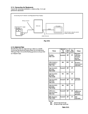
TV monitor Connect when using the camera mode or playing back. 3-1-5. If the type of tape to be used for each adjustment. Particle type metal tape ME ..... Evaporated type metal tape SP ... Fig. 5-3-2. Name Tracking WR5-1NP Video frequency characteristics WR5-7NE Operation check (SP mode) WR5-5NSP Record -ing Tape mode type Standard8 MP Tape speed Usage Tape path SP adjustment Switching position adjustment Hi8 ME SP Frequency characteristics adjustment Standard8 MP SP Operation check (SP mode) WR5-8NSE Operation check (LP mode...
TV monitor Connect when using the camera mode or playing back. 3-1-5. If the type of tape to be used for each adjustment. Particle type metal tape ME ..... Evaporated type metal tape SP ... Fig. 5-3-2. Name Tracking WR5-1NP Video frequency characteristics WR5-7NE Operation check (SP mode) WR5-5NSP Record -ing Tape mode type Standard8 MP Tape speed Usage Tape path SP adjustment Switching position adjustment Hi8 ME SP Frequency characteristics adjustment Standard8 MP SP Operation check (SP mode) WR5-8NSE Operation check (LP mode...

Service Manual
Page 120
...ON Camera+VTR power ON * For page D and F, the data set by users are canceled. 3-1-6. vice mode by pressing the PAUSE button on adjustment Note: After the completion of the all adjustments, cancell the ser- Recording Mode (Standard 8/Hi8) switching (Hi8 model) The record mode (Standard 8/Hi8)...: 01, and return the data to 00 after completing adjustments/repairs and press the PAUSE button of the tape played back. Output Level and Impedance Video output Phono jack, 1 Vp-p, 75Ω, unbalanced, sync negative Audio output Phono jack, -7.5 dBs, (at load impedance 47 kΩ), impedance...
...ON Camera+VTR power ON * For page D and F, the data set by users are canceled. 3-1-6. vice mode by pressing the PAUSE button on adjustment Note: After the completion of the all adjustments, cancell the ser- Recording Mode (Standard 8/Hi8) switching (Hi8 model) The record mode (Standard 8/Hi8)...: 01, and return the data to 00 after completing adjustments/repairs and press the PAUSE button of the tape played back. Output Level and Impedance Video output Phono jack, 1 Vp-p, 75Ω, unbalanced, sync negative Audio output Phono jack, -7.5 dBs, (at load impedance 47 kΩ), impedance...

Service Manual
Page 126
...Battery End Adjustment (VC-215 board) Set the battery end voltage. CAMERA SECTION ADJUSTMENT". 2. The image at the battery end will shorten. Switch setting 1) AUTO FOCUS OFF 2) LCD screen Closed 3) NIGHT SHOT OFF 4) VIDEO LIGHT OFF (VIDEO LIGHT model) Connection: 1) Connect the regulated power supply and the .... 3) Turn on the HOLD switch of the adjusting remote commander. 4) Turn on the power supply. 5) Load a cassette, and set to the camera recording mode. 6) Select page: 0, address: 01, and set data: 01. 7) Decrease the output voltage of the adjusting remote commander. 11) ...
...Battery End Adjustment (VC-215 board) Set the battery end voltage. CAMERA SECTION ADJUSTMENT". 2. The image at the battery end will shorten. Switch setting 1) AUTO FOCUS OFF 2) LCD screen Closed 3) NIGHT SHOT OFF 4) VIDEO LIGHT OFF (VIDEO LIGHT model) Connection: 1) Connect the regulated power supply and the .... 3) Turn on the HOLD switch of the adjusting remote commander. 4) Turn on the power supply. 5) Load a cassette, and set to the camera recording mode. 6) Select page: 0, address: 01, and set data: 01. 7) Decrease the output voltage of the adjusting remote commander. 11) ...

Service Manual
Page 137
...CCD-TRV43/TRV46/TRV46PK) Adjust using a IR receiver jig (J-6082-383-A). Fig. 5-3-18. Adjusting method: 1) Select page: 0, address: 01, and set data: 01. 2) Select page: 3, address: 01, set data: 37, and press the PAUSE button of the adjusting remote commander. 3) Select page: F, address: 68, change the data, set the video...: LASER LINK Red LED is lit) 1. IR Video Deviation Adjustment (VC-215 board) Mode Subject Measurement Point Measuring Instrument Adjustment Page Adjustment Address Specified Value Camera standby Arbitrary VIDEO OUT terminal of IR receiver jig (Terminated at 75...
...CCD-TRV43/TRV46/TRV46PK) Adjust using a IR receiver jig (J-6082-383-A). Fig. 5-3-18. Adjusting method: 1) Select page: 0, address: 01, and set data: 01. 2) Select page: 3, address: 01, set data: 37, and press the PAUSE button of the adjusting remote commander. 3) Select page: F, address: 68, change the data, set the video...: LASER LINK Red LED is lit) 1. IR Video Deviation Adjustment (VC-215 board) Mode Subject Measurement Point Measuring Instrument Adjustment Page Adjustment Address Specified Value Camera standby Arbitrary VIDEO OUT terminal of IR receiver jig (Terminated at 75...
Operating Instructions
Page 1
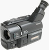
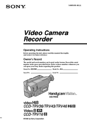
AC-L Serial No. Serial No. Refer to these numbers whenever you call upon your Sony dealer regarding this manual thoroughly, and retain it for future reference. 3-865-333-13 (1) Video Camera Recorder Operating Instructions Before operating the unit, please read this product. Owner's Record The model and serial numbers are located on the bottom. CCD-TRV Model No. Model No. CCD-TRV46 CCD-TRV36/TRV43/TRV46 CCD-TRV16 ©1998 by Sony Corporation Record the serial number in the space provided below.
AC-L Serial No. Serial No. Refer to these numbers whenever you call upon your Sony dealer regarding this manual thoroughly, and retain it for future reference. 3-865-333-13 (1) Video Camera Recorder Operating Instructions Before operating the unit, please read this product. Owner's Record The model and serial numbers are located on the bottom. CCD-TRV Model No. Model No. CCD-TRV46 CCD-TRV36/TRV43/TRV46 CCD-TRV16 ©1998 by Sony Corporation Record the serial number in the space provided below.
Operating Instructions
Page 73
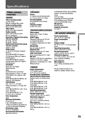
...CCD-TRV16/TRV36: 1 lb 14 oz (870 g) CCD-TRV43/TRV46: 1 lb 15 oz (880 g) excluding the battery pack, lithium battery, cassette and shoulder strap 2 lb 3 oz (1 kg) including the battery pack NPF330, lithium battery CR2025, cassette and shoulder strap Microphone Monaural type Supplied accessories See page 5. Specifications Video camera recorder System Video...adaptor) Average power consumption (when using the battery pack) During camera recording using LCD CCD-TRV16/TRV36: 3.1 W CCD-TRV43/TRV46: 3.2 W Viewfinder CCD-TRV16/TRV36: 2.5 W CCD-TRV43/TRV46: 2.6 W Operating temperature 32°F to 104...
...CCD-TRV16/TRV36: 1 lb 14 oz (870 g) CCD-TRV43/TRV46: 1 lb 15 oz (880 g) excluding the battery pack, lithium battery, cassette and shoulder strap 2 lb 3 oz (1 kg) including the battery pack NPF330, lithium battery CR2025, cassette and shoulder strap Microphone Monaural type Supplied accessories See page 5. Specifications Video camera recorder System Video...adaptor) Average power consumption (when using the battery pack) During camera recording using LCD CCD-TRV16/TRV36: 3.1 W CCD-TRV43/TRV46: 3.2 W Viewfinder CCD-TRV16/TRV36: 2.5 W CCD-TRV43/TRV46: 2.6 W Operating temperature 32°F to 104...


