
Operating Instructions
Page 18
... batteries to avoid possible damage from the sun or lighting apparatus. Unpacking Check that you have the following items: • Speakers (5) • Sub woofer (1) • AM loop antenna (1) • FM wire antenna (1) • Speaker cords (3.5 m × 3, 5 m × 1, 10 m × 2) (12 ft. × 3, 17 ft. × 1, 33 ft. × 2) • Video cord (1) • Remote...
... batteries to avoid possible damage from the sun or lighting apparatus. Unpacking Check that you have the following items: • Speakers (5) • Sub woofer (1) • AM loop antenna (1) • FM wire antenna (1) • Speaker cords (3.5 m × 3, 5 m × 1, 10 m × 2) (12 ft. × 3, 17 ft. × 1, 33 ft. × 2) • Video cord (1) • Remote...

Operating Instructions
Page 21
... other than the one currently displayed on the TV display (OSD), the speaker may damage the system. Stripped cords are touching each speaker cord does not touch another speaker terminal or the bare wire of the speakers may be sure to excessive removal of the surface may result. If no... sound is heard from a speaker other due to follow these precautions when connecting the speakers. If the cords are...
... other than the one currently displayed on the TV display (OSD), the speaker may damage the system. Stripped cords are touching each speaker cord does not touch another speaker terminal or the bare wire of the speakers may be sure to excessive removal of the surface may result. If no... sound is heard from a speaker other due to follow these precautions when connecting the speakers. If the cords are...

Operating Instructions
Page 22
... antenna away from the system and other components. • Be sure to the radio. Terminals for connecting the antennas Connect the AM loop antenna FM wire antenna To the AM terminals FM 75Ω COAXIAL jack AM loop antenna ANTENNA AM 120V 220V y VOLTAGE SELECTOR Y L L PB/CB R R PR/CR ...AUDIO IN AUDIO IN VIDEO IN VIDEO OUT COMPONENT TV VIDEO MONITOR VIDEO OUT SPEAKERS F-RONT+R C-ENTE+R F-RONT+L + - + -+ - Step 2: Antenna Hookups Connect the supplied AM and FM antennas to listen to fully extend the FM...
... antenna away from the system and other components. • Be sure to the radio. Terminals for connecting the antennas Connect the AM loop antenna FM wire antenna To the AM terminals FM 75Ω COAXIAL jack AM loop antenna ANTENNA AM 120V 220V y VOLTAGE SELECTOR Y L L PB/CB R R PR/CR ...AUDIO IN AUDIO IN VIDEO IN VIDEO OUT COMPONENT TV VIDEO MONITOR VIDEO OUT SPEAKERS F-RONT+R C-ENTE+R F-RONT+L + - + -+ - Step 2: Antenna Hookups Connect the supplied AM and FM antennas to listen to fully extend the FM...
Operating Instructions
Page 79
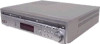
...Intermediate frequency PLL quartz-locked digital synthesizer system 87.5 - 108.0 MHz (100 kHz step) 87.5 - 108.0 MHz (50 kHz step) FM wire antenna 75 ohms, unbalanced 10.7 MHz AM tuner section System PLL quartz-locked digital synthesizer system Tuning range North American models: 530 - 1,710 ...150 × 124.5 mm (35/8 × 6 × 5 inches) 0.8 kg (1 lb 13 oz.) Center European models (SS-CNP2) Other models (SS-CNP75) Speaker system Speaker unit Rated impedance Dimensions (approx.) Mass (approx.) Bass reflex 70 × 100 mm cone type 6 ohms SS-CNP2: 230 × 81 × 121 mm (9 ...
...Intermediate frequency PLL quartz-locked digital synthesizer system 87.5 - 108.0 MHz (100 kHz step) 87.5 - 108.0 MHz (50 kHz step) FM wire antenna 75 ohms, unbalanced 10.7 MHz AM tuner section System PLL quartz-locked digital synthesizer system Tuning range North American models: 530 - 1,710 ...150 × 124.5 mm (35/8 × 6 × 5 inches) 0.8 kg (1 lb 13 oz.) Center European models (SS-CNP2) Other models (SS-CNP75) Speaker system Speaker unit Rated impedance Dimensions (approx.) Mass (approx.) Bass reflex 70 × 100 mm cone type 6 ohms SS-CNP2: 230 × 81 × 121 mm (9 ...


