Service Manual
Page 1
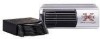
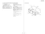
SERVICE MANUAL Ver 1.1 2002.08 CDX-757MX US Model Canadian Model E Model Model Name Using Similar Mechanism CD Drive Mechanism Type Optical Pick-up Name CDX-747X MG-251B-137 KSS-720A SPECIFICATIONS System Compact disc digital audio system Laser diode properties Material: ...Operating temperature -10°C to +55°C (14°F to change without notice. 9-873-618-02 2002H0500-1 C 2002.08 Sony Corporation e Vehicle Company Published by Sony Engineering Corporation COMPACT DISC CHANGER projecting parts and controls Mass Approx. 2.1 kg (4 lb. 10 oz.) Power requirement 12 V DC ...
SERVICE MANUAL Ver 1.1 2002.08 CDX-757MX US Model Canadian Model E Model Model Name Using Similar Mechanism CD Drive Mechanism Type Optical Pick-up Name CDX-747X MG-251B-137 KSS-720A SPECIFICATIONS System Compact disc digital audio system Laser diode properties Material: ...Operating temperature -10°C to +55°C (14°F to change without notice. 9-873-618-02 2002H0500-1 C 2002.08 Sony Corporation e Vehicle Company Published by Sony Engineering Corporation COMPACT DISC CHANGER projecting parts and controls Mass Approx. 2.1 kg (4 lb. 10 oz.) Power requirement 12 V DC ...
Service Manual
Page 2
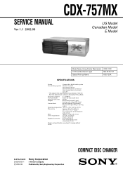
... Removal the magazine assy. NE REMPLACER CES COMPOSANTS QUE PAR DES PIÈCES SONY DONT LES NUMÉROS SONT DONNÉS DANS CE MANUEL OU DANS LES SUPPLÉMENTS PUBLIÉS... PAR SONY. 2 T) beforehand 1) Press the lever (ML.S) assy in the direction of the soldering iron around...lens in the optical pick-up block. ATTENTION AU COMPOSANT AYANT RAPPORT À LA SÉCURITÉ! CDX-757MX SERVICING NOTES NOTES ON HANDLING THE OPTICAL PICKUP BLOCK OR BASE UNIT The laser diode in the optical pick...
... Removal the magazine assy. NE REMPLACER CES COMPOSANTS QUE PAR DES PIÈCES SONY DONT LES NUMÉROS SONT DONNÉS DANS CE MANUEL OU DANS LES SUPPLÉMENTS PUBLIÉS... PAR SONY. 2 T) beforehand 1) Press the lever (ML.S) assy in the direction of the soldering iron around...lens in the optical pick-up block. ATTENTION AU COMPOSANT AYANT RAPPORT À LA SÉCURITÉ! CDX-757MX SERVICING NOTES NOTES ON HANDLING THE OPTICAL PICKUP BLOCK OR BASE UNIT The laser diode in the optical pick...
Service Manual
Page 3
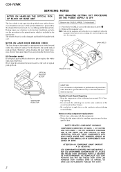
.... Cautions when playing a disc that contains a data track and audio tracks (audio CD data) in Session 2. during disc reading. CDX-757MX TEST DISC This set can play CD-Rs/CD-RWs (recordable CDs/rewritable CDs) on this unit (fig. Folder names can be no more time to which data... can play MP3 files recorded on CD-ROMs, CD-Rs (recordable CDs), and CD-RWs (rewritable CDs). The unit firstly ...
.... Cautions when playing a disc that contains a data track and audio tracks (audio CD data) in Session 2. during disc reading. CDX-757MX TEST DISC This set can play CD-Rs/CD-RWs (recordable CDs/rewritable CDs) on this unit (fig. Folder names can be no more time to which data... can play MP3 files recorded on CD-ROMs, CD-Rs (recordable CDs), and CD-RWs (rewritable CDs). The unit firstly ...
Service Manual
Page 4
... ATRAC3, be played back on your favorite folder repeatedly, or to play a data CD with many characters, this unit, a file name/a folder name is displayed as a CD or an MD. CDX-757MX FAQ- When creating MP3 data CDs, the format of folders or files to the operating instructions. Q3 Is there maximum ... on the unit? The unit can be no more than three characters in your computer)? The unit does not support the play a CD-R/RW containing both music CD data (CD-DA) and MP3 file data? Example: At 64 kbytes, it is recommended. • When naming, be played. As of December...
... ATRAC3, be played back on your favorite folder repeatedly, or to play a data CD with many characters, this unit, a file name/a folder name is displayed as a CD or an MD. CDX-757MX FAQ- When creating MP3 data CDs, the format of folders or files to the operating instructions. Q3 Is there maximum ... on the unit? The unit can be no more than three characters in your computer)? The unit does not support the play a CD-R/RW containing both music CD data (CD-DA) and MP3 file data? Example: At 64 kbytes, it is recommended. • When naming, be played. As of December...
Service Manual
Page 5
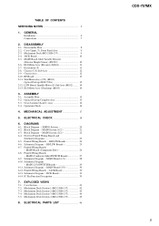
... 2-13. MAIN Section (2/2 22 6-4. Schematic Diagram - MAIN Board (1/3 28 6-10. JACK Board 33 6-14. Mechanism Deck Section-1 (MG-251B-137 42 7-3. ELECTRICAL PARTS LIST 46 CDX-757MX 5 RF Board 13 2-11. Assembly Flow 15 3-2. Gear (Lomini)/(Load 1) Assy 16 3-4. RF/LSW Boards 24 6-6. MAIN (2/3)/SWITCH Boards 29 6-11. Note for Printed Wiring...
... 2-13. MAIN Section (2/2 22 6-4. Schematic Diagram - MAIN Board (1/3 28 6-10. JACK Board 33 6-14. Mechanism Deck Section-1 (MG-251B-137 42 7-3. ELECTRICAL PARTS LIST 46 CDX-757MX 5 RF Board 13 2-11. Assembly Flow 15 3-2. Gear (Lomini)/(Load 1) Assy 16 3-4. RF/LSW Boards 24 6-6. MAIN (2/3)/SWITCH Boards 29 6-11. Note for Printed Wiring...

Service Manual
Page 8
... (ELEVATOR HEIGHT SENSOR) (RV202) (Page 10) 2-7. RF BOARD (Page 13) 2-11. DISASSEMBLY FLOW SECTION 2 DISASSEMBLY Note 1: The process described in the order shown below. 2-1. SET 2-2. CDX-757MX • This set can be disassembled in can not be performed in any order. ELJ MOTOR ASSY (ELEVATOR) (M104) (Page 11) 2-8. SLED MOTOR ASSY (251...
... (ELEVATOR HEIGHT SENSOR) (RV202) (Page 10) 2-7. RF BOARD (Page 13) 2-11. DISASSEMBLY FLOW SECTION 2 DISASSEMBLY Note 1: The process described in the order shown below. 2-1. SET 2-2. CDX-757MX • This set can be disassembled in can not be performed in any order. ELJ MOTOR ASSY (ELEVATOR) (M104) (Page 11) 2-8. SLED MOTOR ASSY (251...
Service Manual
Page 9
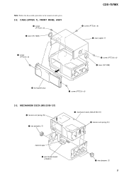
T) 3 screw (PTT2.6 × 6) 4 lever (FLT. 838) 2 front panel assy 2-3. MECHANISM DECK (MG-251B-137) 2 tension coil spring (FL) 1 two dampers (T) 1 screw (PTT2.6 × 6) 4 mechanism deck (MG-251B-137) 2 tension coil spring (FL) filament tape 3 jack flexible board (CNJ901) 1 two dampers (T) 9 Note: Follow the disassembly procedure in the numerical order given. 2-2. CASE (UPPER. T), FRONT PANEL ASSY 3 screw (PTT2.6 × 6) 4 lever (FLT. 838) 1 screw (PTT2.6 × 6) CDX-757MX 3 screw (PTT2.6 × 6) 5 case (upper.
T) 3 screw (PTT2.6 × 6) 4 lever (FLT. 838) 2 front panel assy 2-3. MECHANISM DECK (MG-251B-137) 2 tension coil spring (FL) 1 two dampers (T) 1 screw (PTT2.6 × 6) 4 mechanism deck (MG-251B-137) 2 tension coil spring (FL) filament tape 3 jack flexible board (CNJ901) 1 two dampers (T) 9 Note: Follow the disassembly procedure in the numerical order given. 2-2. CASE (UPPER. T), FRONT PANEL ASSY 3 screw (PTT2.6 × 6) 4 lever (FLT. 838) 1 screw (PTT2.6 × 6) CDX-757MX 3 screw (PTT2.6 × 6) 5 case (upper.
Service Manual
Page 10
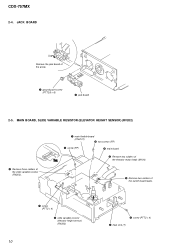
MAIN BOARD, SLIDE VARIABLE RESISTOR (ELEVATOR HEIGHT SENSOR) (RV202) 2 Remove three solders of the slide variable resistor (RV202). 1 main flexible board (CNJ101) 5 two screws (FP) 5 screw (FP) 6 main board 2 Remove two solders of the elevator motor leads (M104). 2 Remove two solders of the arrow. 1 ground point screw (PTT2.6 × 6) 2 jack board 2-5. CDX-757MX 2-4. JACK BOARD Remove the jack board of the switch board leads. 7 screw (PTT2 × 4) 8 slide variable resistor (elevator height sensor) (RV202) 10 3 screw (PTT2 × 4) 4 heat sink (T)
MAIN BOARD, SLIDE VARIABLE RESISTOR (ELEVATOR HEIGHT SENSOR) (RV202) 2 Remove three solders of the slide variable resistor (RV202). 1 main flexible board (CNJ101) 5 two screws (FP) 5 screw (FP) 6 main board 2 Remove two solders of the elevator motor leads (M104). 2 Remove two solders of the arrow. 1 ground point screw (PTT2.6 × 6) 2 jack board 2-5. CDX-757MX 2-4. JACK BOARD Remove the jack board of the switch board leads. 7 screw (PTT2 × 4) 8 slide variable resistor (elevator height sensor) (RV202) 10 3 screw (PTT2 × 4) 4 heat sink (T)

Service Manual
Page 11
ESCUTCHEON (T) 2 Remove the claw in the direction of arrow A. 4 Remove the ditch in the direction of arrow B. 3 two claws A B 5 Remove the escutcheon (T) in the direction of arrow C. 3 claw C 4 ditch 1 screw (T) 11 ELJ MOTOR ASSY (ELEVATOR) (M104) 1 screw (PTT2 × 4) 2 bracket (EVM.S) CDX-757MX 3 ELJ motor assy (elevator) (M104) 2-7. 2-6.
ESCUTCHEON (T) 2 Remove the claw in the direction of arrow A. 4 Remove the ditch in the direction of arrow B. 3 two claws A B 5 Remove the escutcheon (T) in the direction of arrow C. 3 claw C 4 ditch 1 screw (T) 11 ELJ MOTOR ASSY (ELEVATOR) (M104) 1 screw (PTT2 × 4) 2 bracket (EVM.S) CDX-757MX 3 ELJ motor assy (elevator) (M104) 2-7. 2-6.

Service Manual
Page 12
CHASSIS (U.S) SUB ASSY 1 three screws (PTT2 × 4) 5 chassis (U.S) sub assy 2 Remove the edge in the direction of arrow A. 1 two screws (PTT2 × 4) 3 1 screw (PTT2 × 4) 4 spring (SUT) 2-9. CHASSIS ASSY 5 spring (stopper.lower) 6 chassis assy 4 A 1 Turn the gear (EVD.S) fully in the direction A of arrow A. 12 3 2 3 CDX-757MX 2-8.
CHASSIS (U.S) SUB ASSY 1 three screws (PTT2 × 4) 5 chassis (U.S) sub assy 2 Remove the edge in the direction of arrow A. 1 two screws (PTT2 × 4) 3 1 screw (PTT2 × 4) 4 spring (SUT) 2-9. CHASSIS ASSY 5 spring (stopper.lower) 6 chassis assy 4 A 1 Turn the gear (EVD.S) fully in the direction A of arrow A. 12 3 2 3 CDX-757MX 2-8.

Service Manual
Page 13
.... adhesive sheet 3 optical pick-up (KSS-720A) optical pick-up Note: After connecting OP flexible board, fix it . 2-10. RF BOARD 3 two screws (PS2 × 4) CDX-757MX 4 RF board 3 two screws (PS2 × 4) 2 Remove two solders of the sled motor leads (M101). 1 OP flexible board (CN102). 2 Remove four solders of the arrow...
.... adhesive sheet 3 optical pick-up (KSS-720A) optical pick-up Note: After connecting OP flexible board, fix it . 2-10. RF BOARD 3 two screws (PS2 × 4) CDX-757MX 4 RF board 3 two screws (PS2 × 4) 2 Remove two solders of the sled motor leads (M101). 1 OP flexible board (CN102). 2 Remove four solders of the arrow...

Service Manual
Page 14
ELJ MOTOR ASSY (CHUCKING) (M103) 2 two screws (PTT2 × 4) 1 Remove two solders of the arrow. 2-13. LSW BOARD, SPINDLE MOTOR (S) SUB ASSY (M102) 8 two precision screws (P1.7 × 2.2) 7 3 spring (chucking) 1 precision screw (P2 × 2.5) 6 retainer (disc) 5 bracket (CP) 4 precision screw (P2 × 2.2) 2 LSW board 9 Remove the spindle motor (S) sub assy (M102) in the direction of the chucking motor leads (M103). 3 retainer (CHM) 4 ELJ motor assy (chucking) (M103) 14 CDX-757MX 2-12.
ELJ MOTOR ASSY (CHUCKING) (M103) 2 two screws (PTT2 × 4) 1 Remove two solders of the arrow. 2-13. LSW BOARD, SPINDLE MOTOR (S) SUB ASSY (M102) 8 two precision screws (P1.7 × 2.2) 7 3 spring (chucking) 1 precision screw (P2 × 2.5) 6 retainer (disc) 5 bracket (CP) 4 precision screw (P2 × 2.2) 2 LSW board 9 Remove the spindle motor (S) sub assy (M102) in the direction of the chucking motor leads (M103). 3 retainer (CHM) 4 ELJ motor assy (chucking) (M103) 14 CDX-757MX 2-12.

Service Manual
Page 15
... complete assy Note: Insert the shaft (A) first. 15 GEAR (LOMINI) / (LOAD 1) ASSY (Page 16) 3-4. OPTICAL PICK-UP COMPLETE ASSY (Page 15) 3-3. OPERATION CHECK (Page 16) CDX-757MX 3-2. OPTICAL PICK-UP COMPLETE ASSY chuck plate 1 Move the lever (LOCK 3A) in the direction of arrow A, and return it a little in the order shown...
... complete assy Note: Insert the shaft (A) first. 15 GEAR (LOMINI) / (LOAD 1) ASSY (Page 16) 3-4. OPTICAL PICK-UP COMPLETE ASSY (Page 15) 3-3. OPERATION CHECK (Page 16) CDX-757MX 3-2. OPTICAL PICK-UP COMPLETE ASSY chuck plate 1 Move the lever (LOCK 3A) in the direction of arrow A, and return it a little in the order shown...

Service Manual
Page 16
CDX-757MX 3-3. A slit 3 Attach the gear (LOAD 1) assy with its facing inside. 4 stop ring 1.5 (E type) 3-4. OPERATION CHECK 1 Confirm that the slider moves in the direction of arrow C ...
CDX-757MX 3-3. A slit 3 Attach the gear (LOAD 1) assy with its facing inside. 4 stop ring 1.5 (E type) 3-4. OPERATION CHECK 1 Confirm that the slider moves in the direction of arrow C ...
Service Manual
Page 17
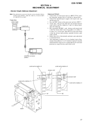
... mentioned above. 7. Press repeatedly the DISC + and - MDX-C7970), load a disc magazine, and place the set placed vertically and horizontally respectively to 6. SECTION 4 MECHANICAL ADJUSTMENT CDX-757MX • Elevator Height (Address) Adjustment Note: This adjustments is finished, check all operations from 5 to confirm that the elevator shaft positions in a range between comb...
... mentioned above. 7. Press repeatedly the DISC + and - MDX-C7970), load a disc magazine, and place the set placed vertically and horizontally respectively to 6. SECTION 4 MECHANICAL ADJUSTMENT CDX-757MX • Elevator Height (Address) Adjustment Note: This adjustments is finished, check all operations from 5 to confirm that the elevator shaft positions in a range between comb...
Service Manual
Page 18
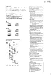
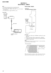
... (DC 14.4 V) + GND master unit oscilloscope (AC range) BUS cable + - nal level is correct or not. Note: Clear RF signal waveform means that supports SONY bus system. Be sure to use ) level: 1.4 ± 0.3 Vp-p When observing the eye pattern, set into play mode by loading the disc (YEDS-18). ...3. FOCUS BIAS CHECK Connection: - Put the set the oscilloscope to TP (RFAC) and TP (VC) on the RF board. 2. CDX-757MX SECTION 5 ELECTRICAL CHECK Note: 1. RF signal waveform VOLT/DIV: 200 mV TIME/DIV: 500 ns (10 : 1 probe in use the disc "YEDS-18" parts...
... (DC 14.4 V) + GND master unit oscilloscope (AC range) BUS cable + - nal level is correct or not. Note: Clear RF signal waveform means that supports SONY bus system. Be sure to use ) level: 1.4 ± 0.3 Vp-p When observing the eye pattern, set into play mode by loading the disc (YEDS-18). ...3. FOCUS BIAS CHECK Connection: - Put the set the oscilloscope to TP (RFAC) and TP (VC) on the RF board. 2. CDX-757MX SECTION 5 ELECTRICAL CHECK Note: 1. RF signal waveform VOLT/DIV: 200 mV TIME/DIV: 500 ns (10 : 1 probe in use the disc "YEDS-18" parts...

Service Manual
Page 19
... mode by loading the disc (YEDS-18). 3. Traverse waveform A 0 V B VOLT/DIV: 500 mV TIME/DIV: 2 ms Center: 0 V A=B traverse waveform (100 track jump waveform) 19 19 CDX-757MX Connect the oscilloscope to 0 V dc, and check this level. * Traverse waveform: This is the tracking error wave form appears when crossing the track. RF Board...
... mode by loading the disc (YEDS-18). 3. Traverse waveform A 0 V B VOLT/DIV: 500 mV TIME/DIV: 2 ms Center: 0 V A=B traverse waveform (100 track jump waveform) 19 19 CDX-757MX Connect the oscilloscope to 0 V dc, and check this level. * Traverse waveform: This is the tracking error wave form appears when crossing the track. RF Board...
Service Manual
Page 20
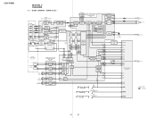
... DAC 1859 PCMD 1858 SELECTOR BCK 1950 LRCK 1856 CLOCK XTAI 1953 GENERATOR XTAO 1954 X101 16.9344MHz CD-ROM/RW SELECT SWITCH Q202 D201 90 R/RW SEL 40 GRSCOR 5 GFS 10 CDDAT 8 CDCLK 9...(Page 21) SDI BCK LRCK A (Page 21) XTAL-IN C (Page 21) TCXRDE D (Page 21) SIGNAL PATH : CD PLAY 20 20 COIL DRIVE 31 VIN4 - 32 M101 M (SLED) 10 VO2 + VO2 - 11 MOTOR DRIVE VIN2 + 22...35 M102 M (SPINDLE) M103 M (CHUHCKING) VO1 + 12 VO1 - 13 MOTOR DRIVE VIN1-B 18 VL0 + FWD 5 4 VL0 - CDX-757MX SECTION 6 DIAGRAMS 6-1. A10 9 - 12, 15 - 19, 21, 8 D-RAM IC102 RAS 5 CAS 23 WE 4 OE 22 TE ...
... DAC 1859 PCMD 1858 SELECTOR BCK 1950 LRCK 1856 CLOCK XTAI 1953 GENERATOR XTAO 1954 X101 16.9344MHz CD-ROM/RW SELECT SWITCH Q202 D201 90 R/RW SEL 40 GRSCOR 5 GFS 10 CDDAT 8 CDCLK 9...(Page 21) SDI BCK LRCK A (Page 21) XTAL-IN C (Page 21) TCXRDE D (Page 21) SIGNAL PATH : CD PLAY 20 20 COIL DRIVE 31 VIN4 - 32 M101 M (SLED) 10 VO2 + VO2 - 11 MOTOR DRIVE VIN2 + 22...35 M102 M (SPINDLE) M103 M (CHUHCKING) VO1 + 12 VO1 - 13 MOTOR DRIVE VIN1-B 18 VL0 + FWD 5 4 VL0 - CDX-757MX SECTION 6 DIAGRAMS 6-1. A10 9 - 12, 15 - 19, 21, 8 D-RAM IC102 RAS 5 CAS 23 WE 4 OE 22 TE ...
Service Manual
Page 22
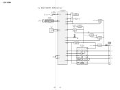
...65 EXTAL 63 XTAL SI 77 SO 76 SCLK 78 BUSON 91 RV201 ELEVATOR HEIGHT (ADDRESS) RV202 ELEVATOR HEIGHT SENSOR DRIVER +8V +8V REGULATOR IC304 CD-ROM/MP3 DECODER (IC601) B+ BATTERY CHECK Q301, 302 +2.5V REGULATOR IC603 SW801 D306 SERVO +3.3V +3.3V REGULATOR IC306 SERVO +5V RESET SIGNAL ...GENERATOR IC303 BUS INTERFACE (FOR SONY BUS) IC302 VCC 14 SO 10 9 SI 11 SCK 1 BUSON OUT BUSON OUT 13 DATA 6 CLK 4 LOF 12 BUSON IN 2 8 RESET RESET SWITCH RST ...
...65 EXTAL 63 XTAL SI 77 SO 76 SCLK 78 BUSON 91 RV201 ELEVATOR HEIGHT (ADDRESS) RV202 ELEVATOR HEIGHT SENSOR DRIVER +8V +8V REGULATOR IC304 CD-ROM/MP3 DECODER (IC601) B+ BATTERY CHECK Q301, 302 +2.5V REGULATOR IC603 SW801 D306 SERVO +3.3V +3.3V REGULATOR IC306 SERVO +5V RESET SIGNAL ...GENERATOR IC303 BUS INTERFACE (FOR SONY BUS) IC302 VCC 14 SO 10 9 SI 11 SCK 1 BUSON OUT BUSON OUT 13 DATA 6 CLK 4 LOF 12 BUSON IN 2 8 RESET RESET SWITCH RST ...
Service Manual
Page 23
...tantalums. • All resistors are taken with part number specified. no mark : CD PLAY ∗ : Impossible to measure • Voltages are in CD play conditions. J : CD PLAY • Circuit Boards Location JACK board SWITCH board LSW board CDX-757MX MAIN board RF board 23 23 pF: µµF 50 WV or less... are not indicated except for repair. • Power voltage is dc 14.4V and fed with regulated dc power supply from CD changer controller. • Voltages and ...
...tantalums. • All resistors are taken with part number specified. no mark : CD PLAY ∗ : Impossible to measure • Voltages are in CD play conditions. J : CD PLAY • Circuit Boards Location JACK board SWITCH board LSW board CDX-757MX MAIN board RF board 23 23 pF: µµF 50 WV or less... are not indicated except for repair. • Power voltage is dc 14.4V and fed with regulated dc power supply from CD changer controller. • Voltages and ...


