
Instruction Manual
Page 1
Instruction Manual and Parts List Ultra High Speed Overedge and Safety Stitch Machine 321D 131M-04 131M-04 / KS 132M-015 134M-04 241M-24 241M-24 / KS 244M-24 251M-35 251M-35 / KH 251M-55 251M-55 / KH 251M-56 251H-56 / KH 321K 131M-04 131M-04 / KS 132M-015 134M-04 241M-24 241M-24 / KS 244M-24 251M-35 251M-35 / KH 251M-55 251M-55 / KH 251M-56 251H-56 / KH ® Singer is a registered trademark of The Singer Company Limited or its affiliated companies. © 2010 Copyright The Singer Company Limited
Instruction Manual and Parts List Ultra High Speed Overedge and Safety Stitch Machine 321D 131M-04 131M-04 / KS 132M-015 134M-04 241M-24 241M-24 / KS 244M-24 251M-35 251M-35 / KH 251M-55 251M-55 / KH 251M-56 251H-56 / KH 321K 131M-04 131M-04 / KS 132M-015 134M-04 241M-24 241M-24 / KS 244M-24 251M-35 251M-35 / KH 251M-55 251M-55 / KH 251M-56 251H-56 / KH ® Singer is a registered trademark of The Singer Company Limited or its affiliated companies. © 2010 Copyright The Singer Company Limited

Instruction Manual
Page 2
... 11 3.7 Machine Threading 12 3.8 Thread Tension Adjustment 13 3.9 Presser foot pressure 14 3.10 Adjusting the Differential Feed Rate 14 3.11 Stitch Length Adjustment 15 3.12 Parts Relation and Timing 16 4 Maintenance 17 4.1 Machine Head Cleaning 17 4.2 Oil Change and Filter Cleaning 17 4.3 Safety Inspection 17 5 Troubleshooting 18
... 11 3.7 Machine Threading 12 3.8 Thread Tension Adjustment 13 3.9 Presser foot pressure 14 3.10 Adjusting the Differential Feed Rate 14 3.11 Stitch Length Adjustment 15 3.12 Parts Relation and Timing 16 4 Maintenance 17 4.1 Machine Head Cleaning 17 4.2 Oil Change and Filter Cleaning 17 4.3 Safety Inspection 17 5 Troubleshooting 18

Instruction Manual
Page 3
... Foot Components 58 6.20 Lubrication Components (1) 60 6.21 Lubrication Components (2) 62 6.22 Silicon Oil Reservoir Components 64 6.23 Exclusive Parts List for 321K series 66 6.24 Thread Stand Components 68 6.25 Accessories 70 6.26 Machine Support Plate For Semi-Submerged Components 72... 6.27 Specific Parts for 321D-251 Hand 321K-251H 73 6.28 Optional Parts 74 6.29 Back Latch Components 76 6.30 Vacuum Suction & AFL Device (Option parts) 78 6.31 ChainCutter DeviceComponents 80 7 Gauge...
... Foot Components 58 6.20 Lubrication Components (1) 60 6.21 Lubrication Components (2) 62 6.22 Silicon Oil Reservoir Components 64 6.23 Exclusive Parts List for 321K series 66 6.24 Thread Stand Components 68 6.25 Accessories 70 6.26 Machine Support Plate For Semi-Submerged Components 72... 6.27 Specific Parts for 321D-251 Hand 321K-251H 73 6.28 Optional Parts 74 6.29 Back Latch Components 76 6.30 Vacuum Suction & AFL Device (Option parts) 78 6.31 ChainCutter DeviceComponents 80 7 Gauge...

Instruction Manual
Page 4
...safety, goggles must be run with a generous amount of cold water. Safety Instructions 1.1 Important Safety Instructions Important When using the machine. Singer will not be held responsible for any electric device is not running , a test must be conducted to assure that all basic safety ...equipment should only be operated by unauthorized changes in the product. Ultra High Speed Overedge and Safety Stitch Machine | Instruction Manual and Parts List 1 When using it as reference when necessary. • Before running the machine, make sure all instructions before using the ...
...safety, goggles must be run with a generous amount of cold water. Safety Instructions 1.1 Important Safety Instructions Important When using the machine. Singer will not be held responsible for any electric device is not running , a test must be conducted to assure that all basic safety ...equipment should only be operated by unauthorized changes in the product. Ultra High Speed Overedge and Safety Stitch Machine | Instruction Manual and Parts List 1 When using it as reference when necessary. • Before running the machine, make sure all instructions before using the ...
Instruction Manual
Page 5
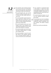
Ultra High Speed Overedge and Safety Stitch Machine | Instruction Manual and Parts List 2 1.2 For Safe Operation • To avoid the risk of electric shock, do not open the motor wiring box and do not touch the components ... far from wheel, belt and motor when the machine is equipped with a servomotor, it . • Clean the machine periodically. Nothing should be placed near those parts. • To avoid injuries never put your fingers next to the rotating hook and the thread take-up lever cover when the machine is...
Ultra High Speed Overedge and Safety Stitch Machine | Instruction Manual and Parts List 2 1.2 For Safe Operation • To avoid the risk of electric shock, do not open the motor wiring box and do not touch the components ... far from wheel, belt and motor when the machine is equipped with a servomotor, it . • Clean the machine periodically. Nothing should be placed near those parts. • To avoid injuries never put your fingers next to the rotating hook and the thread take-up lever cover when the machine is...

Instruction Manual
Page 6
Product Description and Machine Specification 2.1 Product Description Ultra high speed overedge and safety stitch machines Ultra High Speed Overedge and Safety Stitch Machine | Instruction Manual and Parts List 3
Product Description and Machine Specification 2.1 Product Description Ultra high speed overedge and safety stitch machines Ultra High Speed Overedge and Safety Stitch Machine | Instruction Manual and Parts List 3
Instruction Manual
Page 7
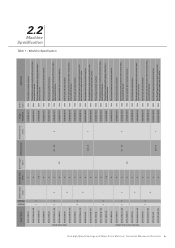
...;cation Table 1 - Machine Specification Ultra High Speed Overedge and Safety Stitch Machine | Instruction Manual and Parts List 4 Singer Model Needle Gauge [mm] Overedge Bight [mm] Stitch Length [mm] Differential Rate Presser Foot Lift [mm] Singer Needle Cat Speed [spm] Application 321D-131M-04 4 321D-131M-04 / KS 4 13 - 321D-132M-015...
...;cation Table 1 - Machine Specification Ultra High Speed Overedge and Safety Stitch Machine | Instruction Manual and Parts List 4 Singer Model Needle Gauge [mm] Overedge Bight [mm] Stitch Length [mm] Differential Rate Presser Foot Lift [mm] Singer Needle Cat Speed [spm] Application 321D-131M-04 4 321D-131M-04 / KS 4 13 - 321D-132M-015...

Instruction Manual
Page 8
2.3 Motor, Motor Pulley and V-Belt Specifications 2.3.1 For 321D series ½ HP 2-pole clutch motor Motor pulley diameter M type v-belt Machine Speed [spm] 5,500 6,000 6,500 7,000 7,500 Table 2 Motor Pulley Diameter [mm] 50 Hz 60 Hz 110 90 115 95 130 105 140 115 150 125 2.3.2 For 321K series Direct drive servo motor and control system. Ultra High Speed Overedge and Safety Stitch Machine | Instruction Manual and Parts List 5
2.3 Motor, Motor Pulley and V-Belt Specifications 2.3.1 For 321D series ½ HP 2-pole clutch motor Motor pulley diameter M type v-belt Machine Speed [spm] 5,500 6,000 6,500 7,000 7,500 Table 2 Motor Pulley Diameter [mm] 50 Hz 60 Hz 110 90 115 95 130 105 140 115 150 125 2.3.2 For 321K series Direct drive servo motor and control system. Ultra High Speed Overedge and Safety Stitch Machine | Instruction Manual and Parts List 5

Instruction Manual
Page 9
3 3.1 Table Cut-Out Diagram 1065 625 475 310 Setup and Adjustment Instructions 40 60 R25 13 R16 65 295 45 C-C R25 65 20 B 225 210 185 141 115 95 50 32 40 R24 48 250 A R24 47 C C B 155 55 40 A 117.95 97.31 118.5 138 190 550 Figure 1 98 110 240 345 358 A-A 25 13 B-B 25 25 1.5 3 9 Ultra High Speed Overedge and Safety Stitch Machine | Instruction Manual and Parts List 6
3 3.1 Table Cut-Out Diagram 1065 625 475 310 Setup and Adjustment Instructions 40 60 R25 13 R16 65 295 45 C-C R25 65 20 B 225 210 185 141 115 95 50 32 40 R24 48 250 A R24 47 C C B 155 55 40 A 117.95 97.31 118.5 138 190 550 Figure 1 98 110 240 345 358 A-A 25 13 B-B 25 25 1.5 3 9 Ultra High Speed Overedge and Safety Stitch Machine | Instruction Manual and Parts List 6

Instruction Manual
Page 10
In case of semi-submerged assembly, the distance between the needle plate top surface and the table top is around 100 mm. 3.2 Machine Installation Install the machine support components and the cloth waste chute as indicated in Figure 2. For fullysubmerged assembly, the distance is around 5.0 mm. 3 2 1 9 10 12 4 5 7 6 8 11 Figure 2 Ultra High Speed Overedge and Safety Stitch Machine | Instruction Manual and Parts List 7
In case of semi-submerged assembly, the distance between the needle plate top surface and the table top is around 100 mm. 3.2 Machine Installation Install the machine support components and the cloth waste chute as indicated in Figure 2. For fullysubmerged assembly, the distance is around 5.0 mm. 3 2 1 9 10 12 4 5 7 6 8 11 Figure 2 Ultra High Speed Overedge and Safety Stitch Machine | Instruction Manual and Parts List 7
Instruction Manual
Page 11
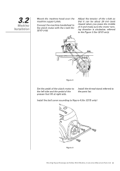
3.2 Machine Installation Mount the machine head over the machine support plate. Install the belt cover according to the parts list. Install the thread stand referred to Figure 4.(for 321D only) 2cm Figure 3 Set the pedal of the clutch motor to the left side and ... the motor turning direction is clockwise, referred to the Figure 3.(for 321D only) Figure 4 Ultra High Speed Overedge and Safety Stitch Machine | Instruction Manual and Parts List 8
3.2 Machine Installation Mount the machine head over the machine support plate. Install the belt cover according to the parts list. Install the thread stand referred to Figure 4.(for 321D only) 2cm Figure 3 Set the pedal of the clutch motor to the left side and ... the motor turning direction is clockwise, referred to the Figure 3.(for 321D only) Figure 4 Ultra High Speed Overedge and Safety Stitch Machine | Instruction Manual and Parts List 8

Instruction Manual
Page 12
..., change the oil, simply remove screw indicated on Figure 7. Figure 6 Figure 7 Ultra High Speed Overedge and Safety Stitch Machine | Instruction Manual and Parts List 9 After that , the oil must be changed as needed. To replace the oil filter, simply remove four screws and remove the top...rotation. To change the oil after the four weeks of the oil level sight window. Remove the rubber plug and fill the lubricant oil (Singer Oil) until the indicator of the oil level between 'L' and 'H' lines of use. 3.3 Lubrication and Oil Drainage Important As this is a ultra...
..., change the oil, simply remove screw indicated on Figure 7. Figure 6 Figure 7 Ultra High Speed Overedge and Safety Stitch Machine | Instruction Manual and Parts List 9 After that , the oil must be changed as needed. To replace the oil filter, simply remove four screws and remove the top...rotation. To change the oil after the four weeks of the oil level sight window. Remove the rubber plug and fill the lubricant oil (Singer Oil) until the indicator of the oil level between 'L' and 'H' lines of use. 3.3 Lubrication and Oil Drainage Important As this is a ultra...

Instruction Manual
Page 13
...to prevent needle thread breakage and fabric damage. Figure 9 (b) Figure 10 Ultra High Speed Overedge and Safety Stitch Machine | Instruction Manual and Parts List 10 3.4 Fill Silicon Oil to Reservoir When sewing in ultra high speed, fill the device with its long groove facing towards you...insert the needle (or remove the old For 1 needle 1 For 2 needle 1 needle). Figure 9 (a) OK! Figure 8 3.5 Needle Attachment (or Replacement) Use only Singer's Cat. 6120 needles Loosen screw '1' as indicated on Figure 8. Insert the needle to the proper depth. Tighten screw '1'.
...to prevent needle thread breakage and fabric damage. Figure 9 (b) Figure 10 Ultra High Speed Overedge and Safety Stitch Machine | Instruction Manual and Parts List 10 3.4 Fill Silicon Oil to Reservoir When sewing in ultra high speed, fill the device with its long groove facing towards you...insert the needle (or remove the old For 1 needle 1 For 2 needle 1 needle). Figure 9 (a) OK! Figure 8 3.5 Needle Attachment (or Replacement) Use only Singer's Cat. 6120 needles Loosen screw '1' as indicated on Figure 8. Insert the needle to the proper depth. Tighten screw '1'.

Instruction Manual
Page 14
... the upper knife holder reaches the lowest position of the needle plate 6 Figure 12 (b) Ultra High Speed Overedge and Safety Stitch Machine | Instruction Manual and Parts List 11 Make sure the upper and lower knives mate positively. Check the cutting by referring to the left position. Loosen screw '1'. Loosen screw '7'ˈ...
... the upper knife holder reaches the lowest position of the needle plate 6 Figure 12 (b) Ultra High Speed Overedge and Safety Stitch Machine | Instruction Manual and Parts List 11 Make sure the upper and lower knives mate positively. Check the cutting by referring to the left position. Loosen screw '1'. Loosen screw '7'ˈ...
Instruction Manual
Page 15
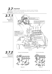
... For three / four thread machine For five thread machine Figure 14 Figure 15 Ultra High Speed Overedge and Safety Stitch Machine | Instruction Manual and Parts List 12 Move the presser foot aside. Any incorrect threading may cause thread brake, uneven stitches or skip stitches. 3.7.1 Easy Threading Method 1 Open three covers...
... For three / four thread machine For five thread machine Figure 14 Figure 15 Ultra High Speed Overedge and Safety Stitch Machine | Instruction Manual and Parts List 12 Move the presser foot aside. Any incorrect threading may cause thread brake, uneven stitches or skip stitches. 3.7.1 Easy Threading Method 1 Open three covers...
Instruction Manual
Page 16
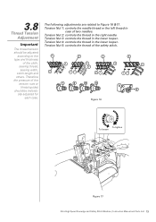
... adjusted according to Figure 16 &17. Figure 16 To tighten To loosen 3 2 1 Figure 17 Ultra High Speed Overedge and Safety Stitch Machine | Instruction Manual and Parts List 13 Therefore the pressure of the cloth, sewing thread, 4 4 4 4 5 sewing width, 2 stitch length and 21 21 21 others. Tension Nut 2: controls the thread in...
... adjusted according to Figure 16 &17. Figure 16 To tighten To loosen 3 2 1 Figure 17 Ultra High Speed Overedge and Safety Stitch Machine | Instruction Manual and Parts List 13 Therefore the pressure of the cloth, sewing thread, 4 4 4 4 5 sewing width, 2 stitch length and 21 21 21 others. Tension Nut 2: controls the thread in...

Instruction Manual
Page 17
... differential feed ratio. As shown on Figure 19. 2 To shrink To stretch 1 Figure 19 Ultra High Speed Overedge and Safety Stitch Machine | Instruction Manual and Parts List 14 3.9 Presser foot pressure Loosen adjusting nut '1' of Figure 18 and turn the adjusting nut 2 to obtain the proper stitch formation. 2 1 Light Heavy Figure...
... differential feed ratio. As shown on Figure 19. 2 To shrink To stretch 1 Figure 19 Ultra High Speed Overedge and Safety Stitch Machine | Instruction Manual and Parts List 14 3.9 Presser foot pressure Loosen adjusting nut '1' of Figure 18 and turn the adjusting nut 2 to obtain the proper stitch formation. 2 1 Light Heavy Figure...

Instruction Manual
Page 18
Turn the handwheel until we have the desired stitch length. Aligning Mark Coarse Fine Handwheel Push Button Figure 20 Ultra High Speed Overedge and Safety Stitch Machine | Instruction Manual and Parts List 15 3.11 Stitch Length Adjustment Important The stitch length adjustment is shown on Figure 20. It is made according to the end and keep it pressed as shown on the handwheel scale. Press button to the sewing fabric, differential feed ration and other factors.
Turn the handwheel until we have the desired stitch length. Aligning Mark Coarse Fine Handwheel Push Button Figure 20 Ultra High Speed Overedge and Safety Stitch Machine | Instruction Manual and Parts List 15 3.11 Stitch Length Adjustment Important The stitch length adjustment is shown on Figure 20. It is made according to the end and keep it pressed as shown on the handwheel scale. Press button to the sewing fabric, differential feed ration and other factors.

Instruction Manual
Page 19
3.12 Parts Relation and Timing 3,4 Thread 5 Thread (a) Top surface of the (a) needle plate Figure 21 (g) (f) Figure 24 (c) (e) (b) (d) Figure 22 Figure 23 Top surface of the needle ... - 0.8 0.5 0.35~2.0 - 0.8 0.5 0.35~2.0 0.6~0.7 0.3 0.35~1.7 - 0.8 0.5 0.35~1.7 - 0.8 0.5 0.35~2.0 - 0.8 0.5 0.35~2.0 - 0.8 0.5 0.35~2.0 1.5 0.8 0.5 0.35~2.0 1.5 0.8 0.5 0.35~2.0 1.5 0.8 0.5 0.35~2.0 1.5 0.8 0.5 0.35~2.0 1.7 0.8 0.5 0.35~2.0 1.7 0.8 0.5 0.35~2.0 Ultra High Speed Overedge and Safety Stitch Machine | Instruction Manual and Parts List 16
3.12 Parts Relation and Timing 3,4 Thread 5 Thread (a) Top surface of the (a) needle plate Figure 21 (g) (f) Figure 24 (c) (e) (b) (d) Figure 22 Figure 23 Top surface of the needle ... - 0.8 0.5 0.35~2.0 - 0.8 0.5 0.35~2.0 0.6~0.7 0.3 0.35~1.7 - 0.8 0.5 0.35~1.7 - 0.8 0.5 0.35~2.0 - 0.8 0.5 0.35~2.0 - 0.8 0.5 0.35~2.0 1.5 0.8 0.5 0.35~2.0 1.5 0.8 0.5 0.35~2.0 1.5 0.8 0.5 0.35~2.0 1.5 0.8 0.5 0.35~2.0 1.7 0.8 0.5 0.35~2.0 1.7 0.8 0.5 0.35~2.0 Ultra High Speed Overedge and Safety Stitch Machine | Instruction Manual and Parts List 16

Instruction Manual
Page 20
... the machine head. The oil filter should be sprayed into the oil window. Ultra High Speed Overedge and Safety Stitch Machine | Instruction Manual and Parts List 17 OK! (Operating) Figure 29 Frequently check if all screws that fix and hold the machine head that it has the proper tension (Except...
... the machine head. The oil filter should be sprayed into the oil window. Ultra High Speed Overedge and Safety Stitch Machine | Instruction Manual and Parts List 17 OK! (Operating) Figure 29 Frequently check if all screws that fix and hold the machine head that it has the proper tension (Except...

