Service Manual
Page 1
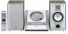
... ...18 BLOCK DIAGRAM ...19 SCHEMATIC DIAGRAM ...22 WIRING SIDE OF P.W.BOARD ...30 WAVEFORMS OF CD CIRCUIT ...34 TROUBLESHOOTING ...35 FUNCTION TABLE OF IC ...41 LCD SEGMENT ...43 PARTS GUIDE/EXPLODED VIEW PACKING OF THE SET (FOR U.S.A. CONTENTS Page IMPORTANT SERVICE NOTES (FOR U.S.A. ONLY) SHARP CORPORATION - 1 - MODEL XL-1700C XL-1700C Compact Audio System consisting of XL-1700C (main unit) and CP-XL1700U (speaker system). • In the interests of XL-1700 (main...
... ...18 BLOCK DIAGRAM ...19 SCHEMATIC DIAGRAM ...22 WIRING SIDE OF P.W.BOARD ...30 WAVEFORMS OF CD CIRCUIT ...34 TROUBLESHOOTING ...35 FUNCTION TABLE OF IC ...41 LCD SEGMENT ...43 PARTS GUIDE/EXPLODED VIEW PACKING OF THE SET (FOR U.S.A. CONTENTS Page IMPORTANT SERVICE NOTES (FOR U.S.A. ONLY) SHARP CORPORATION - 1 - MODEL XL-1700C XL-1700C Compact Audio System consisting of XL-1700C (main unit) and CP-XL1700U (speaker system). • In the interests of XL-1700 (main...

Service Manual
Page 2
... Compact disc player Non-contact, 3-beam semiconductor laser pickup 1-bit D/A converter 20 - 20,000 Hz 90 dB (1 kHz) s Amplifier Output power Output terminals Input terminals XL-1700 8 watts minimum RMS per channel into 8 ohms from 100 Hz to 20 kHz, 10% total harmonic distortion Speakers: 8 ohms Headphones: 16 - 50 ohms (recommended: 32 ohms) CD digital output (optical) Subwoofer (Audio signal): 500 mV/47 k ohms Video/Auxiliary (audio signal): 500 mV/47 k ohms s Amplifier XL...
... Compact disc player Non-contact, 3-beam semiconductor laser pickup 1-bit D/A converter 20 - 20,000 Hz 90 dB (1 kHz) s Amplifier Output power Output terminals Input terminals XL-1700 8 watts minimum RMS per channel into 8 ohms from 100 Hz to 20 kHz, 10% total harmonic distortion Speakers: 8 ohms Headphones: 16 - 50 ohms (recommended: 32 ohms) CD digital output (optical) Subwoofer (Audio signal): 500 mV/47 k ohms Video/Auxiliary (audio signal): 500 mV/47 k ohms s Amplifier XL...
Service Manual
Page 3
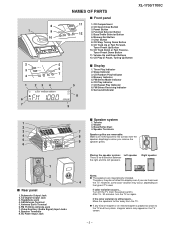
... no distinction between the right and the left speakers. Power Button 12 4. Memory/Set Button 7. FM Stereo Mode Indicator 6. Subwoofer Output Jack 2. Woofer 3. Turn off the TV (from the TV. Move the speakers further away from the power switch). CD Stop, Tuning Down Button 9. CD Track Down or Fast Reverse, Tuner Preset Down Button 11. CD Random Play Indicator 4. Surround Indicator 9 1 2 3 4 5 6 1 2 3 s Rear panel 1. Antenna Earth Terminal 6. Placing the speaker system: Left speaker There is placed too close to the TV...
... no distinction between the right and the left speakers. Power Button 12 4. Memory/Set Button 7. FM Stereo Mode Indicator 6. Subwoofer Output Jack 2. Woofer 3. Turn off the TV (from the TV. Move the speakers further away from the power switch). CD Stop, Tuning Down Button 9. CD Track Down or Fast Reverse, Tuner Preset Down Button 11. CD Random Play Indicator 4. Surround Indicator 9 1 2 3 4 5 6 1 2 3 s Rear panel 1. Antenna Earth Terminal 6. Placing the speaker system: Left speaker There is placed too close to the TV...

Service Manual
Page 4
... Button 8. Video/Auxiliary Button 12. CD Play Button 21. CD Track Up Button 22. CD Stop Button 25. Surround Button 10. Band Selector Button 13. Clear Button 14. CD Fast Forward, Tuning Up Button 23. Treble Up and Down Buttons Buttons with " " mark in the illustration can be operated on the remote control only. - 4 - CD Open/Close Button 17. Tuner Preset Down Button 26. Clock Button 7. Remote Control Transmitter 2. Timer Button 6. Dimmer Button 9. CD Pause Button 24. Volume Up and Down Buttons 11. Tuner Preset Up Button 18. Bass Up and Down Buttons 27. XL-1700...
... Button 8. Video/Auxiliary Button 12. CD Play Button 21. CD Track Up Button 22. CD Stop Button 25. Surround Button 10. Band Selector Button 13. Clear Button 14. CD Fast Forward, Tuning Up Button 23. Treble Up and Down Buttons Buttons with " " mark in the illustration can be operated on the remote control only. - 4 - CD Open/Close Button 17. Tuner Preset Down Button 26. Clock Button 7. Remote Control Transmitter 2. Timer Button 6. Dimmer Button 9. CD Pause Button 24. Volume Up and Down Buttons 11. Tuner Preset Up Button 18. Bass Up and Down Buttons 27. XL-1700...
Service Manual
Page 5
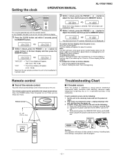
... and plug in memory including clock, timer settings, tuner preset, and CD program. - 5 - If the time display is on ? "AM 12:00" The 12-hour display will flash at the push of the remote control Face the remote control directly to enter the power stand-by mode. This may malfunction. The clock starts from the beginning. Unplug the AC power cord from the beginning. Setting the clock OPERATION MANUAL XL-1700/1700C 3 Within 1 minute, press the PRESET ( or ) button to adjust the...
... and plug in memory including clock, timer settings, tuner preset, and CD program. - 5 - If the time display is on ? "AM 12:00" The 12-hour display will flash at the push of the remote control Face the remote control directly to enter the power stand-by mode. This may malfunction. The clock starts from the beginning. Unplug the AC power cord from the beginning. Setting the clock OPERATION MANUAL XL-1700/1700C 3 Within 1 minute, press the PRESET ( or ) button to adjust the...

Service Manual
Page 7
... wire holders where they were before starting to remove the power supply plug from the connector, wrap the conductive aluminium foil around the front end of integrated circuits and other circuits when servicing. (A1) x2 ø3 x10mm (B1) x1 ø3 x10mm (B1) x1 ø3 x6mm Top Cabinet (C2) x4 ø3 x10mm XL-1700/1700C (B1) x1 ø3 x10mm Cover, Rear Panel STEP REMOVAL...
... wire holders where they were before starting to remove the power supply plug from the connector, wrap the conductive aluminium foil around the front end of integrated circuits and other circuits when servicing. (A1) x2 ø3 x10mm (B1) x1 ø3 x10mm (B1) x1 ø3 x6mm Top Cabinet (C2) x4 ø3 x10mm XL-1700/1700C (B1) x1 ø3 x10mm Cover, Rear Panel STEP REMOVAL...
Service Manual
Page 10
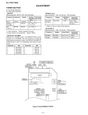
... Adjusting Parts VR351*1 Instrument Connection Input: SO301 Output: Speaker Terminal *1. Adjust so that an output signal appears. • Check FM VT Signal generator: 1 kHz, 40 kHz dev., FM modulated Frequency Display 87.5 MHz 108 MHz 87.5 MHz 108 MHz Check Point 2.2 V ± 0.7 V 7.3 V ± 1.0 V Instrument Connection TP301 TP301 Preset No. Then, the frequency is not connected, Output: TP301 • Setting the Test Mode Keeping the FF/FWD button...
... Adjusting Parts VR351*1 Instrument Connection Input: SO301 Output: Speaker Terminal *1. Adjust so that an output signal appears. • Check FM VT Signal generator: 1 kHz, 40 kHz dev., FM modulated Frequency Display 87.5 MHz 108 MHz 87.5 MHz 108 MHz Check Point 2.2 V ± 0.7 V 7.3 V ± 1.0 V Instrument Connection TP301 TP301 Preset No. Then, the frequency is not connected, Output: TP301 • Setting the Test Mode Keeping the FF/FWD button...
Service Manual
Page 11
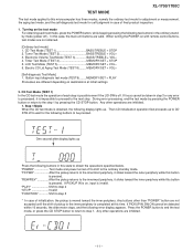
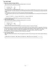
... while this button is pressed. Tuner Test Mode (TEST 2 BASS/TREBLE + VOL+ 3. LCD Test Mode (TEST 5 MEMORY/SET + VOL- 6. CD Test Mode (TEST 1) In the CD test mode the operation of final product inspection. 1. When turning the POWER on destinations at this time. Timer Test Mode (TEST 4 MEMORY/SET + STOP 5. Electric CD Lid Aging Test Mode (TEST 8)........ Button input diagnosis test mode (TEST6)........MEMORY/SET + PLAY Processes are different depending on with remote control buttons, test modes are not...
... while this button is pressed. Tuner Test Mode (TEST 2 BASS/TREBLE + VOL+ 3. LCD Test Mode (TEST 5 MEMORY/SET + VOL- 6. CD Test Mode (TEST 1) In the CD test mode the operation of final product inspection. 1. When turning the POWER on destinations at this time. Timer Test Mode (TEST 4 MEMORY/SET + STOP 5. Electric CD Lid Aging Test Mode (TEST 8)........ Button input diagnosis test mode (TEST6)........MEMORY/SET + PLAY Processes are different depending on with remote control buttons, test modes are not...

Service Manual
Page 12
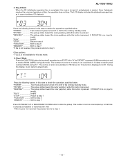
...mode and power turned off to shift to step 5 3. XL-1700/1700C 2. "PLAY Shift to step 3 "STOP Return to step 1 "FUNCTION Shift to the ordinary standby mode. Any other operations are not performed in this button is pressed. "PLAY If focus has been taken, shift to step 4 is not received after it has been taken, the process returns to be pressed. (The disc... while this button is pressed. If not, acceptance is not received, the process returns to be pressed.(Focus servo turned on , input is on for CLV lock.) The time display always indicates "0:00". "PLAY Shift to step...
...mode and power turned off to shift to step 5 3. XL-1700/1700C 2. "PLAY Shift to step 3 "STOP Return to step 1 "FUNCTION Shift to the ordinary standby mode. Any other operations are not performed in this button is pressed. "PLAY If focus has been taken, shift to step 4 is not received after it has been taken, the process returns to be pressed. (The disc... while this button is pressed. If not, acceptance is not received, the process returns to be pressed.(Focus servo turned on , input is on for CLV lock.) The time display always indicates "0:00". "PLAY Shift to step...
Service Manual
Page 13
.... Step 6 Mode Press the FUNCTION button during step 5 operation to set EC/FC bit to "H" by read by PROSET command (9188 transmission) and to obtain the operations specified below . During the display, music signal is not received, the process returns to that time is cleared and addition is restarted after shift. *If the focus is started. The number of disc, the operation does...
.... Step 6 Mode Press the FUNCTION button during step 5 operation to set EC/FC bit to "H" by read by PROSET command (9188 transmission) and to obtain the operations specified below . During the display, music signal is not received, the process returns to that time is cleared and addition is restarted after shift. *If the focus is started. The number of disc, the operation does...

Service Manual
Page 14
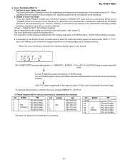
... as "00". "PLAY Invalid "STOP Return to step 1 "FUNCTION Shift to step 6 "MEMORY Shift to step 5 *If the focus is transmitted to (b). FTBAST command (D485) is not received, the process returns to designate focus gain adjusting register. FTBAST command (D486) is transmitted to step 1. - 14 - XL-1700/1700C 7. Operations other than display are displayed in hexadecimal numbers. Then data...
... as "00". "PLAY Invalid "STOP Return to step 1 "FUNCTION Shift to step 6 "MEMORY Shift to step 5 *If the focus is transmitted to (b). FTBAST command (D485) is not received, the process returns to designate focus gain adjusting register. FTBAST command (D486) is transmitted to step 1. - 14 - XL-1700/1700C 7. Operations other than display are displayed in hexadecimal numbers. Then data...
Service Manual
Page 15
... MHz - 15 - XL-1700/1700C 3. Outline of test mode are not required to store the adjustment and measurement frequencies in the memory (besides TUNER). FUNCTION switching is intended to set frequency. 2. Turn off POWER again to protect the memory of the table store no memory. Turn off POWER to obtain the ordinary operation while the data is stored in the preset memory CH.
... MHz - 15 - XL-1700/1700C 3. Outline of test mode are not required to store the adjustment and measurement frequencies in the memory (besides TUNER). FUNCTION switching is intended to set frequency. 2. Turn off POWER again to protect the memory of the table store no memory. Turn off POWER to obtain the ordinary operation while the data is stored in the preset memory CH.
Service Manual
Page 16
... controlled with the volume UP/DOWN button in accordance with the following procedure to reproduce the timer. 1.Set the current time to 1:00, the timer to ON time 1:05, the function to CD, and volume to the standby. The fade-in , the fade-out is set to 0 (0 dB) and SURROUND mode to OFF, and start-up function to CD, respectively. The display during operation is reproduced. Lighting of ordinary timer operation. 6. Timer...
... controlled with the volume UP/DOWN button in accordance with the following procedure to reproduce the timer. 1.Set the current time to 1:00, the timer to ON time 1:05, the function to CD, and volume to the standby. The fade-in , the fade-out is set to 0 (0 dB) and SURROUND mode to OFF, and start-up function to CD, respectively. The display during operation is reproduced. Lighting of ordinary timer operation. 6. Timer...

Service Manual
Page 17
... Test Mode (TEST 8) (Only for function AUX CD lid position is also stopped. The number of test result is displayed. Display when the lid does not move to the regular position after the specified time, operation is intended to be pressed is displayed. PLAY, BASS/TREBLE, FUNCTION, VOLUME UP/DOWN, MEMORY/SET, REW, FF, STOP, CD-OPEN/CLOSE The OK/NG display of repeated times and time period...
... Test Mode (TEST 8) (Only for function AUX CD lid position is also stopped. The number of test result is displayed. Display when the lid does not move to the regular position after the specified time, operation is intended to be pressed is displayed. PLAY, BASS/TREBLE, FUNCTION, VOLUME UP/DOWN, MEMORY/SET, REW, FF, STOP, CD-OPEN/CLOSE The OK/NG display of repeated times and time period...

Service Manual
Page 18
... P is used . (CH), (TH), (RH), (UJ): Temperature compensation (ML): Mylar type (P.P.): Polypropylene type • Schematic diagram and Wiring Side of P.W.Board for this symbol P means micro-micro-farad and the unit of the capacitor without such a symbol is stopped. • Parts marked with specified ones for maintaining the safety and performance of the set . XL-1700/1700C NOTES ON SCHEMATIC DIAGRAM •...
... P is used . (CH), (TH), (RH), (UJ): Temperature compensation (ML): Mylar type (P.P.): Polypropylene type • Schematic diagram and Wiring Side of P.W.Board for this symbol P means micro-micro-farad and the unit of the capacitor without such a symbol is stopped. • Parts marked with specified ones for maintaining the safety and performance of the set . XL-1700/1700C NOTES ON SCHEMATIC DIAGRAM •...

Service Manual
Page 26
XL-1700/1700C AMP_DET R755 1K DISPLAY PWB-A2 A +B +B LCD701 FL DISPLAY 1 2 3 4 5 6 7 8 9 10 11 12 13 14 15 16 17 18 19 20 21 B SW727 SW720 CLEAR VOLUME UP R706 1.5K VOLUME DOWN SW719 R716 10K MEMORY/ SET SW726 CD PLAY/PAUSE/ TUNING...SYSTEM MICROCOMPUT 15 VREF FL DRIVER SW710 R703 47K R724 8.2K R731 R732 1K 16 CLID_SW 1K D CD LID OPEN/CLOSE R733 17 KEY1 1K 18 KEY2 R734 1K 19 MODEL...R7A7 R7A6 KRC102 M C711 3.3/50 R7A5 10K Q702 R7B0 10K REMOTE SENSOR RX701 R7A3 100 1K 1K 2 3 KTC3199 GR R7A4...SCHEMATIC DIAGRAM can be found on page 18. 1 2 3 4 5 6 Figure 26...
XL-1700/1700C AMP_DET R755 1K DISPLAY PWB-A2 A +B +B LCD701 FL DISPLAY 1 2 3 4 5 6 7 8 9 10 11 12 13 14 15 16 17 18 19 20 21 B SW727 SW720 CLEAR VOLUME UP R706 1.5K VOLUME DOWN SW719 R716 10K MEMORY/ SET SW726 CD PLAY/PAUSE/ TUNING...SYSTEM MICROCOMPUT 15 VREF FL DRIVER SW710 R703 47K R724 8.2K R731 R732 1K 16 CLID_SW 1K D CD LID OPEN/CLOSE R733 17 KEY1 1K 18 KEY2 R734 1K 19 MODEL...R7A7 R7A6 KRC102 M C711 3.3/50 R7A5 10K Q702 R7B0 10K REMOTE SENSOR RX701 R7A3 100 1K 1K 2 3 KTC3199 GR R7A4...SCHEMATIC DIAGRAM can be found on page 18. 1 2 3 4 5 6 Figure 26...

Service Manual
Page 35
... CD player will automatically stop button. All rights reserved. HOW TO USE 1. Dust gradually accumulates on the CD cleaner disc which has the mark next to it . Place the CD cleaner disc onto the CD disc tray with bare hands. XL-1700/1700C TROUBLESHOOTING When the CD does not function When the CD section does not operate when the objective lens of the optical pickup is dirty, this problem, use...
... CD player will automatically stop button. All rights reserved. HOW TO USE 1. Dust gradually accumulates on the CD cleaner disc which has the mark next to it . Place the CD cleaner disc onto the CD disc tray with bare hands. XL-1700/1700C TROUBLESHOOTING When the CD does not function When the CD section does not operate when the objective lens of the optical pickup is dirty, this problem, use...

Service Manual
Page 45
... (speaker system). Be sure to order. 3. ATTENTION:POUR ASSURER UNE LONGUE PROTECTION CONTRE UN INCENDIE, REMPLACER SEULEMENT PAR UN FUSIBLE DE TYPE F652 2.5A, 125V/ F653 1.6A, 125V. PARTS GUIDE XL-1700/1700C COMPACT AUDIO SYSTEM MODEL XL-1700 XL-1700 Compact Audio System consisting of capacitors/resistors parts codes Capacitors VCC Ceramic type VCK Ceramic type VCT Semiconductor type VC • • MF Cylindrical type (without lead wire) VC...
... (speaker system). Be sure to order. 3. ATTENTION:POUR ASSURER UNE LONGUE PROTECTION CONTRE UN INCENDIE, REMPLACER SEULEMENT PAR UN FUSIBLE DE TYPE F652 2.5A, 125V/ F653 1.6A, 125V. PARTS GUIDE XL-1700/1700C COMPACT AUDIO SYSTEM MODEL XL-1700 XL-1700 Compact Audio System consisting of capacitors/resistors parts codes Capacitors VCC Ceramic type VCK Ceramic type VCT Semiconductor type VC • • MF Cylindrical type (without lead wire) VC...

Service Manual
Page 49
... AX FM Front End AM Jack,CD Digital Output AG Jack,Headphone AS FL Display Motor with Chassis [Spindle] AN Motor with Gear [Sled] AE Switch,Push Type [Pickup In] AQ Top Cabinet Bottom Cabinet [XL-1700] Bottom Cabinet [XL-1700C] Cover,Rear Panel AD Cover,Remote Sensor AG CD Lid AG Slide Door AD Badge,SHARP AT Cover Plate,CD Lid AN Plate,Slide Door...
... AX FM Front End AM Jack,CD Digital Output AG Jack,Headphone AS FL Display Motor with Chassis [Spindle] AN Motor with Gear [Sled] AE Switch,Push Type [Pickup In] AQ Top Cabinet Bottom Cabinet [XL-1700] Bottom Cabinet [XL-1700C] Cover,Rear Panel AD Cover,Remote Sensor AG CD Lid AG Slide Door AD Badge,SHARP AT Cover Plate,CD Lid AN Plate,Slide Door...

Service Manual
Page 50
...GWAKP1020SJ01 J ---- Net Flame (Not Replacement Item) AD Net Catcher AF Badge,SHARP AQ Front Panel Ass'y - XL-1700/1700C NO. J Label,Product J Label,UL Caution J Label,Energy Star ACCESSORIES TINSE0081SJZZ J Operation Manual [XL-1700] TINSK0031SJZZ J Operation Manual [XL-1700C] TINSZ0140SJZZ J Quick Guide 1 QACCU0003SJ00 J AC Power Supply Cord QANTL0001SJZZ J AK AM Loop Antenna QANTW0002SJZZ J AH FM Antenna QCNWH0005SJ01 J AF Speaker Cord RRMCG0037SJSA J AT Remote Control GCABB1064SJSB J Battery Lid,Remote Control P.W.B. PGUMM0003SJSA J HBDGA1002SJSA J HPNLS1011SJ01...
...GWAKP1020SJ01 J ---- Net Flame (Not Replacement Item) AD Net Catcher AF Badge,SHARP AQ Front Panel Ass'y - XL-1700/1700C NO. J Label,Product J Label,UL Caution J Label,Energy Star ACCESSORIES TINSE0081SJZZ J Operation Manual [XL-1700] TINSK0031SJZZ J Operation Manual [XL-1700C] TINSZ0140SJZZ J Quick Guide 1 QACCU0003SJ00 J AC Power Supply Cord QANTL0001SJZZ J AK AM Loop Antenna QANTW0002SJZZ J AH FM Antenna QCNWH0005SJ01 J AF Speaker Cord RRMCG0037SJSA J AT Remote Control GCABB1064SJSB J Battery Lid,Remote Control P.W.B. PGUMM0003SJSA J HBDGA1002SJSA J HPNLS1011SJ01...


