
Service Manual
Page 2
...1 PWB AND WIRING DIAGRAM 2 REAR COVER 3 SPEAKER UNIT 4 LED DRIVER PWB 5 INLET HARNESS/AC SWITCH 6 POWER SUPPLY PWB 7 TEMPERATURE SENSOR PWB 8 I /F PWB, LCD MODULE, PARTS REPLACEMENT PROCEDURES 4 - 1 CHAPTER 5. IMPORTANT INFORMATION FOR SERVICING THE DISPLAY 1 I /F PWB 9 LCD MODULE 10 KEY PWB 11 TOUCH PANEL ASSEMBLY (PN-T322B) 7 - 1 7 - 3 7 - 4 7 - 5 ... ADJUSTMENT, SETTING 1 INSTALLATION 2 - 1 2 ADJUSTMENT 2 - 5 3 SETTING UP THE PC (TOUCH PANEL DRIVER) 2 - 10 CHAPTER 3. OUTLINE OF THE PRODUCT 1 SPECIFICATIONS 2 PART NAMES AND FUNCTION 3 SCREEN DISPLAY 1 - 1 1 - 6 1 - 11 CHAPTER 6.
...1 PWB AND WIRING DIAGRAM 2 REAR COVER 3 SPEAKER UNIT 4 LED DRIVER PWB 5 INLET HARNESS/AC SWITCH 6 POWER SUPPLY PWB 7 TEMPERATURE SENSOR PWB 8 I /F PWB, LCD MODULE, PARTS REPLACEMENT PROCEDURES 4 - 1 CHAPTER 5. IMPORTANT INFORMATION FOR SERVICING THE DISPLAY 1 I /F PWB 9 LCD MODULE 10 KEY PWB 11 TOUCH PANEL ASSEMBLY (PN-T322B) 7 - 1 7 - 3 7 - 4 7 - 5 ... ADJUSTMENT, SETTING 1 INSTALLATION 2 - 1 2 ADJUSTMENT 2 - 5 3 SETTING UP THE PC (TOUCH PANEL DRIVER) 2 - 10 CHAPTER 3. OUTLINE OF THE PRODUCT 1 SPECIFICATIONS 2 PART NAMES AND FUNCTION 3 SCREEN DISPLAY 1 - 1 1 - 6 1 - 11 CHAPTER 6.
Service Manual
Page 13
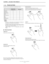
...Drag-and-drop Flicks Press-and-hold can be set to act like a right-click in the Control Panel. Flick your finger ■ TOUCH ACTION SINGLE-TAP Same action as drag-and-drop with your finger...double-tap will not take place. If there is selected in Touch Screen Calibration Utility.For details, see the Touch Panel Driver Operation Manual. 3Refer to lift your finger and move without lifting. When you want to use. TOUCH ACTION Operations that...*1 Same action as double-clicking a mouse. CHAPTER 1. OUTLINE OF THE PRODUCT 2 - 2. PN-T321/T322B OUTLINE OF THE PRODUCT 1 - 9
...Drag-and-drop Flicks Press-and-hold can be set to act like a right-click in the Control Panel. Flick your finger ■ TOUCH ACTION SINGLE-TAP Same action as drag-and-drop with your finger...double-tap will not take place. If there is selected in Touch Screen Calibration Utility.For details, see the Touch Panel Driver Operation Manual. 3Refer to lift your finger and move without lifting. When you want to use. TOUCH ACTION Operations that...*1 Same action as double-clicking a mouse. CHAPTER 1. OUTLINE OF THE PRODUCT 2 - 2. PN-T321/T322B OUTLINE OF THE PRODUCT 1 - 9

Service Manual
Page 25
..., restart. If a message appears prompting you to use the touch panel, the touch panel must be connected to a computer, and the touch panel driver and Pen Software must be detected as follows. PN-T321/T322B INSTALLATION, ADJUSTMENT, SETTING 2 - 10 SYSTEM REQUIREMENTS To use to the touch panel to operate the PC that is a program that enables you...
..., restart. If a message appears prompting you to use the touch panel, the touch panel must be connected to a computer, and the touch panel driver and Pen Software must be detected as follows. PN-T321/T322B INSTALLATION, ADJUSTMENT, SETTING 2 - 10 SYSTEM REQUIREMENTS To use to the touch panel to operate the PC that is a program that enables you...

Service Manual
Page 27
... and click "Exit". 2 ) Disconnect the USB cable. 3 ) Select "Control Panel" from the "Start" menu. 4 ) Click "Uninstall a program". This completes the uninstallation. PN-T321/T322B INSTALLATION, ADJUSTMENT, SETTING 2 - 12 n When the "User Account Control" screen appears, click "Yes" (or "Allow"). 6 ) Remove "NextWindow 2500 Drivers" (Touch Panel Driver). CHAPTER 2. Go to step 6. n When the "User Account Control" screen...
... and click "Exit". 2 ) Disconnect the USB cable. 3 ) Select "Control Panel" from the "Start" menu. 4 ) Click "Uninstall a program". This completes the uninstallation. PN-T321/T322B INSTALLATION, ADJUSTMENT, SETTING 2 - 12 n When the "User Account Control" screen appears, click "Yes" (or "Allow"). 6 ) Remove "NextWindow 2500 Drivers" (Touch Panel Driver). CHAPTER 2. Go to step 6. n When the "User Account Control" screen...

Service Manual
Page 51
...driver PWB cable 2 LCD module cable 3 Speaker L cable 4 Speaker R cable 5 Key FFC 6 Power supply harness 7 Temperature watch control cable 8 AMP power supply cable 9 Inlet harness F AC harness 5 Parts code 0QP0000000021 0QP0000000020 0QP0000000025 0QP0000000024 0QP0000000023 0QP0000000022 0QP0000000029 0QP0000000026 0QP0000000028 0QP0000000027 PN-T321/T322B... lead-free solder with a protective sheet spread over the LCD panel. 1. Always use gloves. n Use the earth band when performing the procedures. Parts name A LED driver PWB B Power supply PWB C Temperature sensor PWB D Main...
...driver PWB cable 2 LCD module cable 3 Speaker L cable 4 Speaker R cable 5 Key FFC 6 Power supply harness 7 Temperature watch control cable 8 AMP power supply cable 9 Inlet harness F AC harness 5 Parts code 0QP0000000021 0QP0000000020 0QP0000000025 0QP0000000024 0QP0000000023 0QP0000000022 0QP0000000029 0QP0000000026 0QP0000000028 0QP0000000027 PN-T321/T322B... lead-free solder with a protective sheet spread over the LCD panel. 1. Always use gloves. n Use the earth band when performing the procedures. Parts name A LED driver PWB B Power supply PWB C Temperature sensor PWB D Main...

Service Manual
Page 66
...to the machine with the FFC. INLET HARNESS/AC SWITCH". Remove four screws B (3 x 6, silver), and disengage the plate at three positions. LED DRIVER PWB". Otherwise the FFC may be broken. Turn over the display, and remove the front cabinet from the key PWB. 3Refer to remove. DISASSEMBLY AND... to the front cabinet is as shown in the PWB side. REAR COVER". 2 ) Remove the speaker unit. 3Refer to page 7 - 3 "2. CHAPTER 7. TOUCH PANEL ASSEMBLY (PN-T322B) 1 ) Remove the rear cover. 3Refer to page 7 - 4 "3. Slide in the arrow direction of the USB cable in the illustration.
...to the machine with the FFC. INLET HARNESS/AC SWITCH". Remove four screws B (3 x 6, silver), and disengage the plate at three positions. LED DRIVER PWB". Otherwise the FFC may be broken. Turn over the display, and remove the front cabinet from the key PWB. 3Refer to remove. DISASSEMBLY AND... to the front cabinet is as shown in the PWB side. REAR COVER". 2 ) Remove the speaker unit. 3Refer to page 7 - 3 "2. CHAPTER 7. TOUCH PANEL ASSEMBLY (PN-T322B) 1 ) Remove the rear cover. 3Refer to page 7 - 4 "3. Slide in the arrow direction of the USB cable in the illustration.

Service Manual
Page 71
...n When the main unit is pressed strongly or a considerable pressure is applied to confirm that "NextWindow 2500 Drivers" are installed on the control panel Is "Finger is performed. Yes No Are the drivers installed? (Check to the sensor section, the sensor correction process is used as an input device." No... tens of the PC or to a self-powered USB hub. Connect it connected to the USB port of seconds), the touch panel does not respond to page 8 - 5 " 8. PN-T321/T322B TROUBLESHOOTING 8 - 4 Yes No Is it to the USB port of "RSCU" checked? NO RESPONSE FOR TOUCHING No Is the...
...n When the main unit is pressed strongly or a considerable pressure is applied to confirm that "NextWindow 2500 Drivers" are installed on the control panel Is "Finger is performed. Yes No Are the drivers installed? (Check to the sensor section, the sensor correction process is used as an input device." No... tens of the PC or to a self-powered USB hub. Connect it connected to the USB port of seconds), the touch panel does not respond to page 8 - 5 " 8. PN-T321/T322B TROUBLESHOOTING 8 - 4 Yes No Is it to the USB port of "RSCU" checked? NO RESPONSE FOR TOUCHING No Is the...
Service Manual
Page 74
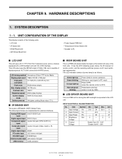
...Supply PWB Unit n Temperature Sensor Board Unit n Speaker (L/R) ■ LCD UNIT This unit uses a 31.5" TFT (Thin Film Transistor) panel, and is MT8223H of the following terminals are implemented for driving the LED backlight incorporated in PC input) Power [OFF] (when the remote... control is OFF) Temperature anomaly (when it is set by OSD) ■ LED DRIVER BOARD UNIT This is capable of displaying about 16,770,000 colors (6-bit+HI-FRCcolors). INPUT ELECTRICAL CHARACTERISTICS No. SYSTEM DESCRIPTION 1 - 1. n LCD Unit...
...Supply PWB Unit n Temperature Sensor Board Unit n Speaker (L/R) ■ LCD UNIT This unit uses a 31.5" TFT (Thin Film Transistor) panel, and is MT8223H of the following terminals are implemented for driving the LED backlight incorporated in PC input) Power [OFF] (when the remote... control is OFF) Temperature anomaly (when it is set by OSD) ■ LED DRIVER BOARD UNIT This is capable of displaying about 16,770,000 colors (6-bit+HI-FRCcolors). INPUT ELECTRICAL CHARACTERISTICS No. SYSTEM DESCRIPTION 1 - 1. n LCD Unit...
Service Manual
Page 77
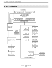
BLOCK DIAGRAM LCD Module LED edge light PWB LED edge light PWB 31.5 inch LCD panel 1366 x RGB x 768 dots 16.7M colors LED edge light PWB LED edge light PWB LCD drivers PWB LED Drive PWB unit Thermo sensor IR/KEY POWER SUPPLY PWB POWER SW AC inlet Power cable LSI MT8223H DDR2 EEPROM FLASH USB RS232C Audio out A/V in Component PC Audio VGA DVI HDMI SPEAKER AMP IF (Interface) PWB unit Speaker L Speaker R PN-T321/T322B HARDWARE DESCRIPTIONS 9 - 4 CHAPTER 9. HARDWARE DESCRIPTIONS 4.
BLOCK DIAGRAM LCD Module LED edge light PWB LED edge light PWB 31.5 inch LCD panel 1366 x RGB x 768 dots 16.7M colors LED edge light PWB LED edge light PWB LCD drivers PWB LED Drive PWB unit Thermo sensor IR/KEY POWER SUPPLY PWB POWER SW AC inlet Power cable LSI MT8223H DDR2 EEPROM FLASH USB RS232C Audio out A/V in Component PC Audio VGA DVI HDMI SPEAKER AMP IF (Interface) PWB unit Speaker L Speaker R PN-T321/T322B HARDWARE DESCRIPTIONS 9 - 4 CHAPTER 9. HARDWARE DESCRIPTIONS 4.