
Service Manual
Page 2
... CHAPTER 1. CONTROLLING THE MONITOR WITH A PC 1 RS-232C 3 - 1 CHAPTER 4. IMPORTANT INFORMATION FOR SERVICING THE DISPLAY 1 I /F PWB 9 LCD MODULE 10 KEY PWB 11 TOUCH PANEL ASSEMBLY (PN-T322B) 7 - 1 7 - 3 7 - 4 7 - 5 7 - 6 7 - 8 7 - 8 7 - 9 7 - 13 7 - 15 7 - 16 CHAPTER 8. FIRMWARE UPDATA PROCEDURES/EDID...PROCEDURES Of TOUCH PANEL INSPECTION TOOL 5 - 8 CHAPTER 7. DISASSEMBLY AND ASSEMBLY 1 PWB AND WIRING DIAGRAM 2 REAR COVER 3 SPEAKER UNIT 4 LED DRIVER PWB 5 INLET HARNESS/AC SWITCH 6 POWER SUPPLY PWB 7 TEMPERATURE SENSOR PWB 8 I /F PWB, LCD MODULE, PARTS REPLACEMENT PROCEDURES 4 - ...
... CHAPTER 1. CONTROLLING THE MONITOR WITH A PC 1 RS-232C 3 - 1 CHAPTER 4. IMPORTANT INFORMATION FOR SERVICING THE DISPLAY 1 I /F PWB 9 LCD MODULE 10 KEY PWB 11 TOUCH PANEL ASSEMBLY (PN-T322B) 7 - 1 7 - 3 7 - 4 7 - 5 7 - 6 7 - 8 7 - 8 7 - 9 7 - 13 7 - 15 7 - 16 CHAPTER 8. FIRMWARE UPDATA PROCEDURES/EDID...PROCEDURES Of TOUCH PANEL INSPECTION TOOL 5 - 8 CHAPTER 7. DISASSEMBLY AND ASSEMBLY 1 PWB AND WIRING DIAGRAM 2 REAR COVER 3 SPEAKER UNIT 4 LED DRIVER PWB 5 INLET HARNESS/AC SWITCH 6 POWER SUPPLY PWB 7 TEMPERATURE SENSOR PWB 8 I /F PWB, LCD MODULE, PARTS REPLACEMENT PROCEDURES 4 - ...
Service Manual
Page 13
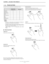
...clicking a mouse. Quickly touch twice. If there is selected in the Control Panel. PRESS-AND-HOLD*1 Same action as double-clicking a mouse. PN-T321/T322B OUTLINE OF THE PRODUCT 1 - 9 DRAG-AND-DROP Same action as left-clicking a mouse. FLICKS*1 Flick your finger in Touch Screen Calibration ...Utility.For details, see the Touch Panel Driver Operation Manual. 3Refer to page 2 - 11 "3 - 3. Be sure to use. Single-tap Double-tap Drag-and...
...clicking a mouse. Quickly touch twice. If there is selected in the Control Panel. PRESS-AND-HOLD*1 Same action as double-clicking a mouse. PN-T321/T322B OUTLINE OF THE PRODUCT 1 - 9 DRAG-AND-DROP Same action as left-clicking a mouse. FLICKS*1 Flick your finger in Touch Screen Calibration ...Utility.For details, see the Touch Panel Driver Operation Manual. 3Refer to page 2 - 11 "3 - 3. Be sure to use. Single-tap Double-tap Drag-and...

Service Manual
Page 25
..." in "Computer" or "My Computer". 6 ) Double-click the "TouchPanel" folder. 7 ) Double-click "NextWindow_2500_Driver_xxxx_Generic.exe" (Touch Panel Driver). In Windows 7, perform calibration using a USB hub, use the touch panel, start the Touch Screen Calibration Utility and perform calibration. MEMO n...the CD-ROM drive in Control Panel. Follow the on-screen instructions to output a resolution of supplying a 500 mA current). PN-T321/T322B INSTALLATION, ADJUSTMENT, SETTING 2 - 10 Computer OS PC/AT compatible computer with administrator authority. CAUTION n This can only be ...
..." in "Computer" or "My Computer". 6 ) Double-click the "TouchPanel" folder. 7 ) Double-click "NextWindow_2500_Driver_xxxx_Generic.exe" (Touch Panel Driver). In Windows 7, perform calibration using a USB hub, use the touch panel, start the Touch Screen Calibration Utility and perform calibration. MEMO n...the CD-ROM drive in Control Panel. Follow the on-screen instructions to output a resolution of supplying a 500 mA current). PN-T321/T322B INSTALLATION, ADJUSTMENT, SETTING 2 - 10 Computer OS PC/AT compatible computer with administrator authority. CAUTION n This can only be ...

Service Manual
Page 27
INSTALLATION, ADJUSTMENT, SETTING 3 - 4. This step is finished, restart your computer. Follow the on -screen instructions. PN-T321/T322B INSTALLATION, ADJUSTMENT, SETTING 2 - 12 Follow the on -screen instructions. n In Windows XP, click "Add or Remove Programs...Vista, remove "Touch Screen Calibration Utility". n When the "User Account Control" screen appears, click "Yes" (or "Allow"). 6 ) Remove "NextWindow 2500 Drivers" (Touch Panel Driver). Go to step 6. n When the "User Account Control" screen appears, click "Yes" (or "Allow"). 7 ) When uninstallation is not necessary in ...
INSTALLATION, ADJUSTMENT, SETTING 3 - 4. This step is finished, restart your computer. Follow the on -screen instructions. PN-T321/T322B INSTALLATION, ADJUSTMENT, SETTING 2 - 12 Follow the on -screen instructions. n In Windows XP, click "Add or Remove Programs...Vista, remove "Touch Screen Calibration Utility". n When the "User Account Control" screen appears, click "Yes" (or "Allow"). 6 ) Remove "NextWindow 2500 Drivers" (Touch Panel Driver). Go to step 6. n When the "User Account Control" screen appears, click "Yes" (or "Allow"). 7 ) When uninstallation is not necessary in ...

Service Manual
Page 51
... the LCD panel. 1. Cable name 1 LED driver PWB cable 2 LCD module cable 3 Speaker L cable 4 Speaker R cable 5 Key FFC 6 Power supply harness 7 Temperature watch control cable 8 AMP power supply cable 9 Inlet harness F AC harness 5 Parts code 0QP0000000021 0QP0000000020 0QP0000000025 0QP0000000024 0QP0000000023 0QP0000000022 0QP0000000029 0QP0000000026 0QP0000000028 0QP0000000027 PN-T321/T322B DISASSEMBLY AND ASSEMBLY 7 - 1 n When servicing...
... the LCD panel. 1. Cable name 1 LED driver PWB cable 2 LCD module cable 3 Speaker L cable 4 Speaker R cable 5 Key FFC 6 Power supply harness 7 Temperature watch control cable 8 AMP power supply cable 9 Inlet harness F AC harness 5 Parts code 0QP0000000021 0QP0000000020 0QP0000000025 0QP0000000024 0QP0000000023 0QP0000000022 0QP0000000029 0QP0000000026 0QP0000000028 0QP0000000027 PN-T321/T322B DISASSEMBLY AND ASSEMBLY 7 - 1 n When servicing...

Service Manual
Page 55
... ASSEMBLY 4. Remove the harness from the LED drive PWB. 3 ) Unscrew 4pcs of screws (4 x 6 (black)), and then remove the angle. SCREW TIGHTENING TORQUE n 0.167 - 0.196N•m PN-T321/T322B DISASSEMBLY AND ASSEMBLY 7 - 5 LED DRIVER PWB 1 ) Unscrew 4pcs of screws (3 x 6 (silver)), and remove the LED...
... ASSEMBLY 4. Remove the harness from the LED drive PWB. 3 ) Unscrew 4pcs of screws (4 x 6 (black)), and then remove the angle. SCREW TIGHTENING TORQUE n 0.167 - 0.196N•m PN-T321/T322B DISASSEMBLY AND ASSEMBLY 7 - 5 LED DRIVER PWB 1 ) Unscrew 4pcs of screws (3 x 6 (silver)), and remove the LED...

Service Manual
Page 66
...A Cable band The orientation of the ground terminals is connected to the machine with the FFC. INLET HARNESS/AC SWITCH". PN-T321/T322B DISASSEMBLY AND ASSEMBLY 7 - 16 REAR COVER". 2 ) Remove the speaker unit. 3Refer to page 7 - 3 "2. Turn... it from the machine excessively since the key PWB attached to remove. DISASSEMBLY AND ASSEMBLY 11. TOUCH PANEL ASSEMBLY (PN-T322B) 1 ) Remove the rear cover. 3Refer to page 7 - 4 "3. SPEAKER UNIT". 3 ) Disconnect the connector... tapes and one screw A (3 x 6, silver), and remove the control PWB. LED DRIVER PWB". Otherwise the FFC may be broken.
...A Cable band The orientation of the ground terminals is connected to the machine with the FFC. INLET HARNESS/AC SWITCH". PN-T321/T322B DISASSEMBLY AND ASSEMBLY 7 - 16 REAR COVER". 2 ) Remove the speaker unit. 3Refer to page 7 - 3 "2. Turn... it from the machine excessively since the key PWB attached to remove. DISASSEMBLY AND ASSEMBLY 11. TOUCH PANEL ASSEMBLY (PN-T322B) 1 ) Remove the rear cover. 3Refer to page 7 - 4 "3. SPEAKER UNIT". 3 ) Disconnect the connector... tapes and one screw A (3 x 6, silver), and remove the control PWB. LED DRIVER PWB". Otherwise the FFC may be broken.

Service Manual
Page 70
... the external speaker and related sections? No abnormality Any defect with a new one . Is there any abnormality in the LED driver PWB? Is there any abnormality in the speaker? No abnormality Any problem with the board? Abnormality Replace the abnormal part with ... IS GENERATED/ REPRODUCED SOUND ABNORMALITY Is the sound volume set to minimum or mute? Abnormality Abnormality Abnormality Abnormality Readjust and reset. PN-T321/T322B TROUBLESHOOTING 8 - 3 Is there any abnormality in the audio cable? CHAPTER 8. CAUTION You must use the RS-232C cable ...
... the external speaker and related sections? No abnormality Any defect with a new one . Is there any abnormality in the LED driver PWB? Is there any abnormality in the speaker? No abnormality Any problem with the board? Abnormality Replace the abnormal part with ... IS GENERATED/ REPRODUCED SOUND ABNORMALITY Is the sound volume set to minimum or mute? Abnormality Abnormality Abnormality Abnormality Readjust and reset. PN-T321/T322B TROUBLESHOOTING 8 - 3 Is there any abnormality in the audio cable? CHAPTER 8. CAUTION You must use the RS-232C cable ...

Service Manual
Page 71
...menu of "RSCU" checked? in the "User Touch Yes Environment Setting" of the control panel.) Yes Yes Is the OS Windows7? Install the drivers. No No (Open the back cabinet.) Are the control PWB, the USB cable, and the FFC cable properly connected? During this process (for...(protection glass with the USB cable? MEMO n When the main unit is pressed strongly or a considerable pressure is applied to page 8 - 5 " 8. PN-T321/T322B TROUBLESHOOTING 8 - 4 Is "NextWindow Low Rider Touch Screen" Yes displayed in "Human Interface Devices" of the PC or to a self-powered USB hub?
...menu of "RSCU" checked? in the "User Touch Yes Environment Setting" of the control panel.) Yes Yes Is the OS Windows7? Install the drivers. No No (Open the back cabinet.) Are the control PWB, the USB cable, and the FFC cable properly connected? During this process (for...(protection glass with the USB cable? MEMO n When the main unit is pressed strongly or a considerable pressure is applied to page 8 - 5 " 8. PN-T321/T322B TROUBLESHOOTING 8 - 4 Is "NextWindow Low Rider Touch Screen" Yes displayed in "Human Interface Devices" of the PC or to a self-powered USB hub?
Service Manual
Page 74
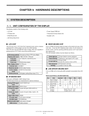
... in PC input) Power [OFF] (when the remote control is OFF) Temperature anomaly (when it is set by OSD) ■ LED DRIVER BOARD UNIT This is MT8223H of displaying about 16,770,000 colors (6-bit+HI-FRCcolors). The LED indication (status of the front side. Analog...to gray) Screen display mode MVA/ Normally black Surface process Anti glare coating (Haze value 17%) ■ I /F Board Unit n IR/SW Board Unit n LED Driver Board Unit n Power Supply PWB Unit n Temperature Sensor Board Unit n Speaker (L/R) ■ LCD UNIT This unit uses a 31.5" TFT (Thin Film Transistor) panel...
... in PC input) Power [OFF] (when the remote control is OFF) Temperature anomaly (when it is set by OSD) ■ LED DRIVER BOARD UNIT This is MT8223H of displaying about 16,770,000 colors (6-bit+HI-FRCcolors). The LED indication (status of the front side. Analog...to gray) Screen display mode MVA/ Normally black Surface process Anti glare coating (Haze value 17%) ■ I /F Board Unit n IR/SW Board Unit n LED Driver Board Unit n Power Supply PWB Unit n Temperature Sensor Board Unit n Speaker (L/R) ■ LCD UNIT This unit uses a 31.5" TFT (Thin Film Transistor) panel...
Service Manual
Page 77
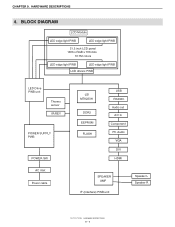
BLOCK DIAGRAM LCD Module LED edge light PWB LED edge light PWB 31.5 inch LCD panel 1366 x RGB x 768 dots 16.7M colors LED edge light PWB LED edge light PWB LCD drivers PWB LED Drive PWB unit Thermo sensor IR/KEY POWER SUPPLY PWB POWER SW AC inlet Power cable LSI MT8223H DDR2 EEPROM FLASH USB RS232C Audio out A/V in Component PC Audio VGA DVI HDMI SPEAKER AMP IF (Interface) PWB unit Speaker L Speaker R PN-T321/T322B HARDWARE DESCRIPTIONS 9 - 4 HARDWARE DESCRIPTIONS 4. CHAPTER 9.
BLOCK DIAGRAM LCD Module LED edge light PWB LED edge light PWB 31.5 inch LCD panel 1366 x RGB x 768 dots 16.7M colors LED edge light PWB LED edge light PWB LCD drivers PWB LED Drive PWB unit Thermo sensor IR/KEY POWER SUPPLY PWB POWER SW AC inlet Power cable LSI MT8223H DDR2 EEPROM FLASH USB RS232C Audio out A/V in Component PC Audio VGA DVI HDMI SPEAKER AMP IF (Interface) PWB unit Speaker L Speaker R PN-T321/T322B HARDWARE DESCRIPTIONS 9 - 4 HARDWARE DESCRIPTIONS 4. CHAPTER 9.