Programmer Manual
Page 2
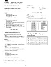
...List of the key number on display is used if an application needs different keyboard layout other than that key position. ing method 1 only. This reset returns all memory and keyboard contents. keyboard layout) Keyboard layout report (on the AC switch. SERVICE (SRV) MODE The SRV key is disabled....(SRV′) position. 3) Turn on the position to (SRV) position from (SRV′) position. • MRS-2 Used to allow PGM program loop reset. Disable MASTER PRESET NOTES: 1: When the 0 key is pressed, the key of program reports JOB# 900 950 951 970 Report name SRV-mode program ...
...List of the key number on display is used if an application needs different keyboard layout other than that key position. ing method 1 only. This reset returns all memory and keyboard contents. keyboard layout) Keyboard layout report (on the AC switch. SERVICE (SRV) MODE The SRV key is disabled....(SRV′) position. 3) Turn on the position to (SRV) position from (SRV′) position. • MRS-2 Used to allow PGM program loop reset. Disable MASTER PRESET NOTES: 1: When the 0 key is pressed, the key of program reports JOB# 900 950 951 970 Report name SRV-mode program ...
Programmer Manual
Page 3
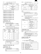
[JOB# 900] All parameters contained for PGM2 mode Initial text mode programming JOB# JOB#//Programming data(ABCD) General Z1 reset counter Hourly Z1 reset counter PLU Z1/Z2 reset counter Cashier Z1/Z2 reset counter PBLU Z1 reset counter General Z2 reset counter Daily net Z2 reset counter GT2 counter GT3 counter Training GT counter Secret code for the SRV mode as listed Key operation. 900 → @/FOR → CA/AT Header graphical logo (Default:Graphical LOGO only) Date/Time Machine No./Consective No.
[JOB# 900] All parameters contained for PGM2 mode Initial text mode programming JOB# JOB#//Programming data(ABCD) General Z1 reset counter Hourly Z1 reset counter PLU Z1/Z2 reset counter Cashier Z1/Z2 reset counter PBLU Z1 reset counter General Z2 reset counter Daily net Z2 reset counter GT2 counter GT3 counter Training GT counter Secret code for the SRV mode as listed Key operation. 900 → @/FOR → CA/AT Header graphical logo (Default:Graphical LOGO only) Date/Time Machine No./Consective No.
Programmer Manual
Page 9
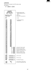
...1. Fraction treatment Round off Round up Round down 911-A 0 5 1 2 #911-B: 1. C/D check of consecutive No. Resetting of UPC No Yes 2. Z1 resetting, resets GT Enable/Disable 1. Printing of data on X report GT1 (NET) GT2 (+) Skip Skip Print Print Skip Print GT3 (-) ... 4 5 #909-C: 1. Fraction treatment 1. in void-mode totalizer and manager void totalizer on Z1 report 1. Printing of training GT on PLU resetting report 2. C/D checking at "0") #910-B: 1. Add void-mode transaction to hourly total report 2. Printing of data on the X report 2. ...
...1. Fraction treatment Round off Round up Round down 911-A 0 5 1 2 #911-B: 1. C/D check of consecutive No. Resetting of UPC No Yes 2. Z1 resetting, resets GT Enable/Disable 1. Printing of data on X report GT1 (NET) GT2 (+) Skip Skip Print Print Skip Print GT3 (-) ... 4 5 #909-C: 1. Fraction treatment 1. in void-mode totalizer and manager void totalizer on Z1 report 1. Printing of training GT on PLU resetting report 2. C/D checking at "0") #910-B: 1. Add void-mode transaction to hourly total report 2. Printing of data on the X report 2. ...
Programmer Manual
Page 13
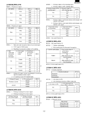
... #928-A: 1. Taxable status of PLU / UPC which has not beens in PGM 1. 919-D: 1. Conversion SBTL printing of PLU on each media's preset) 1. Program reset in GLU system acts on bill when it is made printed 1. Header line on slip Check only Check & Charge 2. Open store/Close store for PB... According to its associated Department Non-taxable 929-D 0 5 2 [JOB#930∼941] MRS = 0000 RESET REPORT COUNTER "0000" Job# @/FOR ABCD CA/AT Initial value of the on bill when it is set at "Non-taxable" by PGM According to...
... #928-A: 1. Taxable status of PLU / UPC which has not beens in PGM 1. 919-D: 1. Conversion SBTL printing of PLU on each media's preset) 1. Program reset in GLU system acts on bill when it is made printed 1. Header line on slip Check only Check & Charge 2. Open store/Close store for PB... According to its associated Department Non-taxable 929-D 0 5 2 [JOB#930∼941] MRS = 0000 RESET REPORT COUNTER "0000" Job# @/FOR ABCD CA/AT Initial value of the on bill when it is set at "Non-taxable" by PGM According to...
Programmer Manual
Page 47
... time interval range and PLU code range can be printed by the following procedure. All XXXXXX Start No. @/FOR XXXXXX End No. *3 When 2 is not reset when canceled. *1 X1: Daily X report X2: Periodic X report Z1: Daily Z report Z2: Periodic Z report MGR/Flash-read ) NON-ACCESSED UPC DELETE OF NON-ACCESSED UPC...that point. OP X/Z reports: These reports are printed. Example: Daily general report; OP X/Z, X1/Z1,X2/Z2 MODE The following key entry sequence Reading JOB# Resetting @/FOR Range is stopped, the consecutive number or Z counter doesn't return to cancel.
... time interval range and PLU code range can be printed by the following procedure. All XXXXXX Start No. @/FOR XXXXXX End No. *3 When 2 is not reset when canceled. *1 X1: Daily X report X2: Periodic X report Z1: Daily Z report Z2: Periodic Z report MGR/Flash-read ) NON-ACCESSED UPC DELETE OF NON-ACCESSED UPC...that point. OP X/Z reports: These reports are printed. Example: Daily general report; OP X/Z, X1/Z1,X2/Z2 MODE The following key entry sequence Reading JOB# Resetting @/FOR Range is stopped, the consecutive number or Z counter doesn't return to cancel.
Service Manual
Page 1
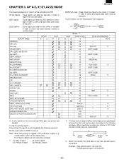
SPECIFICATIONS 1-1 CHAPTER 2. HARDWARE DESCRIPTION 4-1 CHAPTER 5. SERVICE PRECAUTION 7-1 CHAPTER 8. SERVICE RESET AND MASTER RESET 3-1 CHAPTER 4. WHEN WORKING ON THIS MACHINE MAKE SURE THAT THE POWER CORD IS REMOVED FROM THE WALL OUTLET. ...2-1 CHAPTER 3. This document has been published to replace these parts with " " are subject to change without notice. SERVICE MANUAL ELECTRONIC CASH REGISTER MODEL ER-A450T SRV Key : LKGIM7113RCZZ PRINTER : PR-45M ("U" and "A" version) CAUTION EXTREME CAUTION MUST BE TAKEN WHEN SERVICING THIS MACHINE. TEST FUNCTION 5-1 CHAPTER 6....
SPECIFICATIONS 1-1 CHAPTER 2. HARDWARE DESCRIPTION 4-1 CHAPTER 5. SERVICE PRECAUTION 7-1 CHAPTER 8. SERVICE RESET AND MASTER RESET 3-1 CHAPTER 4. WHEN WORKING ON THIS MACHINE MAKE SURE THAT THE POWER CORD IS REMOVED FROM THE WALL OUTLET. ...2-1 CHAPTER 3. This document has been published to replace these parts with " " are subject to change without notice. SERVICE MANUAL ELECTRONIC CASH REGISTER MODEL ER-A450T SRV Key : LKGIM7113RCZZ PRINTER : PR-45M ("U" and "A" version) CAUTION EXTREME CAUTION MUST BE TAKEN WHEN SERVICING THIS MACHINE. TEST FUNCTION 5-1 CHAPTER 6....
Service Manual
Page 3
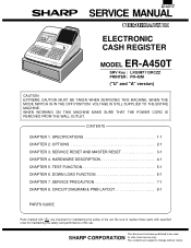
... or cancellation of entry limits), which are prohibited and no display is present. [Functions] • Function for each key position • SRV': System reset • SRV: Service mode (Service programming) • PGM2: Allows programming of daily sales total. • X2/Z2: Allows reading or... totals for a specified period. • OFF: Switching off the display to ordinary cashiers. • X1/Z1: Allows reading and resetting of an item that is finalized by authorized person such as a manager (e.g. Specifications 1) Printer (PR-45M) • No. In the SRV' mode, key ...
... or cancellation of entry limits), which are prohibited and no display is present. [Functions] • Function for each key position • SRV': System reset • SRV: Service mode (Service programming) • PGM2: Allows programming of daily sales total. • X2/Z2: Allows reading or... totals for a specified period. • OFF: Switching off the display to ordinary cashiers. • X1/Z1: Allows reading and resetting of an item that is finalized by authorized person such as a manager (e.g. Specifications 1) Printer (PR-45M) • No. In the SRV' mode, key ...

Service Manual
Page 8
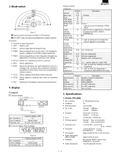
.... 3) Plug in the AC cord to the wall outlet. 4) While holding down JOURNAL FEED key, turn to allow PGM program loop reset. 2. This reset returns all programming back to its initial settings and return keyboard back to the wall outlet. 4) While holding down JOURNAL FEED key and ...′) position. • MRS-2 Used to clear all memory contents and return machine back to its operational state after a lockup has occurred. SERVICE RESET AND MASTER RESET 1. Procedure • Method 1 1) Unplug the AC cord from the wall outlet. 2) Set the mode switch to (SRV′) position. 3) Plug...
.... 3) Plug in the AC cord to the wall outlet. 4) While holding down JOURNAL FEED key, turn to allow PGM program loop reset. 2. This reset returns all programming back to its initial settings and return keyboard back to the wall outlet. 4) While holding down JOURNAL FEED key and ...′) position. • MRS-2 Used to clear all memory contents and return machine back to its operational state after a lockup has occurred. SERVICE RESET AND MASTER RESET 1. Procedure • Method 1 1) Unplug the AC cord from the wall outlet. 2) Set the mode switch to (SRV′) position. 3) Plug...
Service Manual
Page 12
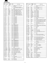
...71 P56 72 P57 73 P60 /NEJ NU /NER VSS TRG1 /PSTOP /CKDCR2 OPDS FVPON FMRS /SLIPLMP /STOP /ERS 74 P61 75 P62 76 P63 77 P64 /DRS /CSS /CDS /RR 78 P65 /RSS 79 P66 80 ...Nu (GND) IN Nu (GND) OUT Nu (GND) IN Nu (GND) OUT Nu (GND) OUT Nu (GND) OUT ER signal for RS232 (Equipment Ready) IN DR signal for RS232 (Data set Ready) IN CS signal for RS232 (Clear to Send...INPUT FOR SSP INTERRUPT INPUT GND EVENT READ CANCEL (to CKDC) LOAD REQUEST (to CKDC) SHIFT ENABLE (from CKDC) FISCAL MEMORY RESET (Nu) FISCAL MEMORY BUSY (Nu) FISCAL MEMORY READY (Nu) POP-UP DISPLAY SENSOR (Nu) GND DATA BUS 0 DATA ...
...71 P56 72 P57 73 P60 /NEJ NU /NER VSS TRG1 /PSTOP /CKDCR2 OPDS FVPON FMRS /SLIPLMP /STOP /ERS 74 P61 75 P62 76 P63 77 P64 /DRS /CSS /CDS /RR 78 P65 /RSS 79 P66 80 ...Nu (GND) IN Nu (GND) OUT Nu (GND) IN Nu (GND) OUT Nu (GND) OUT Nu (GND) OUT ER signal for RS232 (Equipment Ready) IN DR signal for RS232 (Data set Ready) IN CS signal for RS232 (Clear to Send...INPUT FOR SSP INTERRUPT INPUT GND EVENT READ CANCEL (to CKDC) LOAD REQUEST (to CKDC) SHIFT ENABLE (from CKDC) FISCAL MEMORY RESET (Nu) FISCAL MEMORY BUSY (Nu) FISCAL MEMORY READY (Nu) POP-UP DISPLAY SENSOR (Nu) GND DATA BUS 0 DATA ...

Service Manual
Page 13
... 40 D3 41 GND 42 D4 43 158 TWAIT D5 44 157 NU D6 45 156 NU D7 46 155 NU SSPRQ 47 154 NU RESET 48 153 NU INT2 49 152 STH2 INT3 50 151 SCK2 RXDI 51 150 HTS2 TXDI 52 149 SLMTR SCKI 53 148 SLMTS IRQ0 54...
... 40 D3 41 GND 42 D4 43 158 TWAIT D5 44 157 NU D6 45 156 NU D7 46 155 NU SSPRQ 47 154 NU RESET 48 153 NU INT2 49 152 STH2 INT3 50 151 SCK2 RXDI 51 150 HTS2 TXDI 52 149 SLMTR SCKI 53 148 SLMTS IRQ0 54...
Service Manual
Page 14
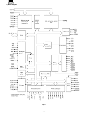
... SDT1~7 DT1~9 TRG DOTEN TRG Fig. 2-4 4 - 6 2) Block diagram A23~A0 IRLON ROS1 ROS2 RAS1 RAS2 RAS3 OPTCS D0~D7 AS RD WR RDO WRO Φ RESET RES VRESC POFF MD0 MD1 WAIT EXWAIT RJRST SLRST *PRST RJTMG SLTMG PTMG Address decode External CS Internal CS RASEL Image control SSP comparison register...
... SDT1~7 DT1~9 TRG DOTEN TRG Fig. 2-4 4 - 6 2) Block diagram A23~A0 IRLON ROS1 ROS2 RAS1 RAS2 RAS3 OPTCS D0~D7 AS RD WR RDO WRO Φ RESET RES VRESC POFF MD0 MD1 WAIT EXWAIT RJRST SLRST *PRST RJTMG SLTMG PTMG Address decode External CS Internal CS RASEL Image control SSP comparison register...

Service Manual
Page 15
... 36 SDT2 37 SDT1 38 D0 39 D1 40 D2 41 D3 42 GND 43 D4 44 D5 45 D6 46 D7 47 SPRQ 48 RESET 49 SHEN 50 INT3 In/ Out Function Out Receipt side paper feed solenoid (NU) Out Journal side paper feed solenoid (NU) Out Printer partial cut... signal (NU) Out Slip printer paper feed singnal (NU) Out Slip printer release signal (NU) Out Slip printer motor drive signal (NU) Out Peripheral output reset Out Dot head trigger signal (NU) Out Dot head trigger signal (NU) In Power off signal input In (NU) Out 8 bit serial port output (for...
... 36 SDT2 37 SDT1 38 D0 39 D1 40 D2 41 D3 42 GND 43 D4 44 D5 45 D6 46 D7 47 SPRQ 48 RESET 49 SHEN 50 INT3 In/ Out Function Out Receipt side paper feed solenoid (NU) Out Journal side paper feed solenoid (NU) Out Printer partial cut... signal (NU) Out Slip printer paper feed singnal (NU) Out Slip printer release signal (NU) Out Slip printer motor drive signal (NU) Out Peripheral output reset Out Dot head trigger signal (NU) Out Dot head trigger signal (NU) In Power off signal input In (NU) Out 8 bit serial port output (for...

Service Manual
Page 16
... expansion option Out ROM 1 chip select signal Out ROM 2 chip select signal (NU) Out RAM 2 chip select signal Out RAM 1 chip select signal In Printer reset signal In FOR TPRC (NU) +5V Out Printer dot signal 4 (NU) Out Printer dot signal 3 (NU) Out Printer dot signal 2 (NU) Out Printer dot signal... 4 SD 5 SE 6 SF 7 SG 8 GND 9 VDD 10 KR4 11 KR10 12 KR11 13 NU 14 HTS 15 STH 16 CKDC8 48 ST7 47 ST6 46 /RESETS 45 /SHEN 44 ERC 43 LDRQ 42 GND 41 40 39 GND 38 37 36 /RES0 35 VDD 34 GND 33 KR7 /SCK 17 ST0...
... expansion option Out ROM 1 chip select signal Out ROM 2 chip select signal (NU) Out RAM 2 chip select signal Out RAM 1 chip select signal In Printer reset signal In FOR TPRC (NU) +5V Out Printer dot signal 4 (NU) Out Printer dot signal 3 (NU) Out Printer dot signal 2 (NU) Out Printer dot signal... 4 SD 5 SE 6 SF 7 SG 8 GND 9 VDD 10 KR4 11 KR10 12 KR11 13 NU 14 HTS 15 STH 16 CKDC8 48 ST7 47 ST6 46 /RESETS 45 /SHEN 44 ERC 43 LDRQ 42 GND 41 40 39 GND 38 37 36 /RES0 35 VDD 34 GND 33 KR7 /SCK 17 ST0...

Service Manual
Page 17
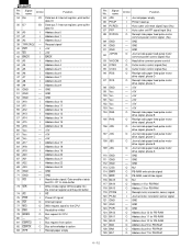
SYMBOL SIGNAL NAME IN/ OUT FUNCTION 32 KR6 KR6 IN KEY RETURN 6 33 KR7 KR7 IN KEY RETURN 7 34 AVRF GND 35 AVDD VDD 36 /RESET /RES0 IN 37 XT2 38 XT1 32.768 KHz 39 IC GND 40 X2 41 X1 4.19 MHz 42 VSS1 GND 43 LDRQ LDRQ IN ...LORD REQUEST 44 ERC ERC IN EVENT READ CANCEL 45 SHEN /SHEN OUT SHIFT ENABLE 46 /RES1 /RESETS OUT SYSTEM TO RESET 47 ST6 ST6 OUT KEY STROBE 6 48 ST7 ST7 OUT KEY STROBE 7 49 ST8 ST8 OUT KEY STROBE 8 50 ST9 NU OUT KEY...
SYMBOL SIGNAL NAME IN/ OUT FUNCTION 32 KR6 KR6 IN KEY RETURN 6 33 KR7 KR7 IN KEY RETURN 7 34 AVRF GND 35 AVDD VDD 36 /RESET /RES0 IN 37 XT2 38 XT1 32.768 KHz 39 IC GND 40 X2 41 X1 4.19 MHz 42 VSS1 GND 43 LDRQ LDRQ IN ...LORD REQUEST 44 ERC ERC IN EVENT READ CANCEL 45 SHEN /SHEN OUT SHIFT ENABLE 46 /RES1 /RESETS OUT SYSTEM TO RESET 47 ST6 ST6 OUT KEY STROBE 6 48 ST7 ST7 OUT KEY STROBE 7 49 ST8 ST8 OUT KEY STROBE 8 50 ST9 NU OUT KEY...

Service Manual
Page 18
... GND 32 D5 33 D6 34 D7 35 A0 36 A1 37 A2 38 NU 39 INTI 40 WI 41 BACK 42 A3 43 158 RESET A4 44 157 BRAS A5 45 156 BRAS A6 46 155 BD0 A7 47 154 BD1 A8 48 153 BD2 A9 49 152 GND GND...
... GND 32 D5 33 D6 34 D7 35 A0 36 A1 37 A2 38 NU 39 INTI 40 WI 41 BACK 42 A3 43 158 RESET A4 44 157 BRAS A5 45 156 BRAS A6 46 155 BD0 A7 47 154 BD1 A8 48 153 BD2 A9 49 152 GND GND...
Service Manual
Page 20
... POPI 124 BA12 125 BA11 126 BA10 127 BA9 128 BA8 129 BA7 In/Out Function I Journal paper empty I Printer head up I Auto cutter unit reset signal input (Nu) I Address bus 9 50 GND - GND -
... POPI 124 BA12 125 BA11 126 BA10 127 BA9 128 BA8 129 BA7 In/Out Function I Journal paper empty I Printer head up I Auto cutter unit reset signal input (Nu) I Address bus 9 50 GND - GND -

Service Manual
Page 21
... 146 BD5 147 GND 148 BD4 149 BD3 150 GND 151 GND 152 GND 153 BD2 154 BD1 155 BD0 156 BRAS 157 BRAS 158 RESET 159 GND 160 NU In/Out Function I/O Data bus 7 for PB-RAM I/O Data bus 6 for PB-RAM I /O Data bus 3 for PB-RAM - GND I/O Data bus... HIGH (Nu) O PB-RAM chip select: Active LOW I /O Data bus 0 for PB-RAM 2-5. GND I/O Data bus 2 for PB-RAM I/O Data bus 1 for PB-RAM I TPRC1 reset signal - GND - name 130 GND 131 GND 132 GND 133 BA6 134 BA5 135 BA4 136 BA3 137 BA2 138 BA1 139 PHAI 140 Vcc...
... 146 BD5 147 GND 148 BD4 149 BD3 150 GND 151 GND 152 GND 153 BD2 154 BD1 155 BD0 156 BRAS 157 BRAS 158 RESET 159 GND 160 NU In/Out Function I/O Data bus 7 for PB-RAM I/O Data bus 6 for PB-RAM I /O Data bus 3 for PB-RAM - GND I/O Data bus... HIGH (Nu) O PB-RAM chip select: Active LOW I /O Data bus 0 for PB-RAM 2-5. GND I/O Data bus 2 for PB-RAM I/O Data bus 1 for PB-RAM I TPRC1 reset signal - GND - name 130 GND 131 GND 132 GND 133 BA6 134 BA5 135 BA4 136 BA3 137 BA2 138 BA1 139 PHAI 140 Vcc...
Service Manual
Page 24
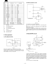
.... The signal STOP is internally driven. This circuit monitors +24V supply voltage. 4 - 16 The CPU contains an oscillation circuit from a 19.66 MHz ceramic oscillator. Reset (POFF) circuit +24V +5V INT0 IRQ0 MPCA7 13 54 48 POFF D7 R114 8.2KG + C83 1µ 50V R115 15KG R116 9.1KG 1SS133 R117 2.7K R118... 143 144 145 146 147 148 149 150 151 152 153 154 155 156 157 158 159 160 I ID IS ISU IO 3S ON6 Name ER-A770 I/O VCC VCC GND GND /CSD VCC IS TRNDTD NC O /DTRD NC O /RTSD NC O RCVDTD GND IS /CTSD GND IS /DSRD GND IS TRNRDYD NC...
.... The signal STOP is internally driven. This circuit monitors +24V supply voltage. 4 - 16 The CPU contains an oscillation circuit from a 19.66 MHz ceramic oscillator. Reset (POFF) circuit +24V +5V INT0 IRQ0 MPCA7 13 54 48 POFF D7 R114 8.2KG + C83 1µ 50V R115 15KG R116 9.1KG 1SS133 R117 2.7K R118... 143 144 145 146 147 148 149 150 151 152 153 154 155 156 157 158 159 160 I ID IS ISU IO 3S ON6 Name ER-A770 I/O VCC VCC GND GND /CSD VCC IS TRNDTD NC O /DTRD NC O /RTSD NC O RCVDTD GND IS /CTSD GND IS /DSRD GND IS TRNRDYD NC...
Service Manual
Page 25
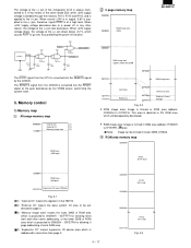
...be addressed in page 0. ( 3) "Memory image area" means the lower 32KB of ROM area which is projected to 000000H ~ 007FFFH for allowing reset start and other vector addressing, or the lower 32KB of ROM area which is projected to 008000H ~ 00FE7FH for allowing 0 page addressing of work ... is formed in RAM area address 1F0000H to area other reason, the voltage at the gate backed-up by the VRAM power, performing the system reset. 5. Memory control 1) Memory map All range memory map 000000H Internal I/O (*1) External I/O (*2) 1C0000H Memory image area (*3) RAM area (10M byte) 0 page ...
...be addressed in page 0. ( 3) "Memory image area" means the lower 32KB of ROM area which is projected to 000000H ~ 007FFFH for allowing reset start and other vector addressing, or the lower 32KB of ROM area which is projected to 008000H ~ 00FE7FH for allowing 0 page addressing of work ... is formed in RAM area address 1F0000H to area other reason, the voltage at the gate backed-up by the VRAM power, performing the system reset. 5. Memory control 1) Memory map All range memory map 000000H Internal I/O (*1) External I/O (*2) 1C0000H Memory image area (*3) RAM area (10M byte) 0 page ...
Service Manual
Page 26
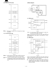
... and does not exist as an internal signal. The control register in MPCA7 allows selection of no stack process immediately after resetting. 4 - 18 Note used in the ER-A445P. (Not used) Access is performed with two RAM chip select signals, RAS2 and RAS3. The 0 page control ... Address A23~A14 200000H~3FFFFFH 1C0000H~1DFFFFH Address decorder 008000H~ 00F7FFH *1 1E0000H~1FFFFFH RAS3 RAS1 RAS2 DOI D Q Control register S8F CK R RESET MPCA7 Fig. 5-8 Access is performed with the control register. RAM area memory map 100000H NOT USE 1C0000H 1E0000H 200000H RAS1 128K Byte RAS2 128K...
... and does not exist as an internal signal. The control register in MPCA7 allows selection of no stack process immediately after resetting. 4 - 18 Note used in the ER-A445P. (Not used) Access is performed with two RAM chip select signals, RAS2 and RAS3. The 0 page control ... Address A23~A14 200000H~3FFFFFH 1C0000H~1DFFFFH Address decorder 008000H~ 00F7FFH *1 1E0000H~1FFFFFH RAS3 RAS1 RAS2 DOI D Q Control register S8F CK R RESET MPCA7 Fig. 5-8 Access is performed with the control register. RAM area memory map 100000H NOT USE 1C0000H 1E0000H 200000H RAS1 128K Byte RAS2 128K...


