Service Manual
Page 2
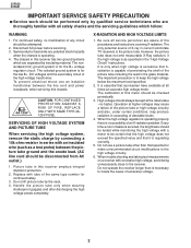
... 1. Do not use an isolation transformer between the picture tube ground and the anode lead. (AC line cord should be attempted. 2. 32F630 32F631 IMPORTANT SERVICE SAFETY PRECAUTION Ë Service work should be checked periodically. 3. SERVICING OF HIGH VOLTAGE SYSTEM AND PICTURE TUBE When servicing the... shock hazards when the chassis is essential that Xradiation is no modification of the picture tube including the lead in current solid state TV receivers is necessary to the high voltage circuitry. 6. It is operating. 4. Semiconductor heat sinks are aware of the high voltage ...
... 1. Do not use an isolation transformer between the picture tube ground and the anode lead. (AC line cord should be attempted. 2. 32F630 32F631 IMPORTANT SERVICE SAFETY PRECAUTION Ë Service work should be checked periodically. 3. SERVICING OF HIGH VOLTAGE SYSTEM AND PICTURE TUBE When servicing the... shock hazards when the chassis is essential that Xradiation is no modification of the picture tube including the lead in current solid state TV receivers is necessary to the high voltage circuitry. 6. It is operating. 4. Semiconductor heat sinks are aware of the high voltage ...
Service Manual
Page 4
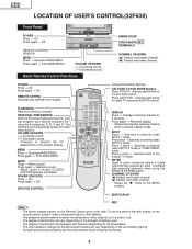
...32F630) Front Panel POWER Press → On. Press again → Off. VOLUME UP/DOWN ( + ) Increases sound. ( ) Decreases sound. POWER Press → On. Press again → Off. Infrared Transmitter Window CATV/DVD-TV/VCR MODE buttons Press TV/VCR →Signals sent will vary depending on On-Screen... Display. PERSONAL PREFERENCE With the Personal Preference buttons, you can be for cable TV converter and DVD control. VOLUME UP/DOWN ( + ...
...32F630) Front Panel POWER Press → On. Press again → Off. VOLUME UP/DOWN ( + ) Increases sound. ( ) Decreases sound. POWER Press → On. Press again → Off. Infrared Transmitter Window CATV/DVD-TV/VCR MODE buttons Press TV/VCR →Signals sent will vary depending on On-Screen... Display. PERSONAL PREFERENCE With the Personal Preference buttons, you can be for cable TV converter and DVD control. VOLUME UP/DOWN ( + ...
Service Manual
Page 5
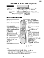
.... REMOTE KEYPAD Accesses any channel from keypad. VOLUME UP/DOWN ( + ) Increases sound. ( ) Decreases sound. Changes or selects the TV adjustments on the surrounding lighting. MUTE Press → Mutes sound. Press again → Restores sound. Press again → Removes display. CHANNEL... 4 times → Switches back to previous channel. Moves the Æ mark on the strength of illumination will vary depending on the MENU screens. 32F630 32F631 LOCATION OF USER'S CONTROL(32F631) Front Panel POWER POWER Press → On. Press again → Off. VOL + CH VOLUME UP...
.... REMOTE KEYPAD Accesses any channel from keypad. VOLUME UP/DOWN ( + ) Increases sound. ( ) Decreases sound. Changes or selects the TV adjustments on the surrounding lighting. MUTE Press → Mutes sound. Press again → Restores sound. Press again → Removes display. CHANNEL... 4 times → Switches back to previous channel. Moves the Æ mark on the strength of illumination will vary depending on the MENU screens. 32F630 32F631 LOCATION OF USER'S CONTROL(32F631) Front Panel POWER POWER Press → On. Press again → Off. VOL + CH VOLUME UP...
Service Manual
Page 6
...mode. 6 Operate receiver for malfunctioning components. Apply 120V AC using an external DC supply, TV must be on PWB-A, wired into one side of picture tube. 2. Connect an accurate... "01" (Y-mute on . X-RADIATION PROTECTOR CIRCUIT TEST After service has been performed on the screen. 7. Allow for warm up and adjust all customer controls for accurate input voltage. 2. If ...the operation of the horizontal oscillator does not stop in test signal. 3. 32F630 32F631 Note: INSTALLATION AND SERVICE INSTRUCTIONS (1) When performing any adjustments to TP651 (Pin 3) and...
...mode. 6 Operate receiver for malfunctioning components. Apply 120V AC using an external DC supply, TV must be on PWB-A, wired into one side of picture tube. 2. Connect an accurate... "01" (Y-mute on . X-RADIATION PROTECTOR CIRCUIT TEST After service has been performed on the screen. 7. Allow for warm up and adjust all customer controls for accurate input voltage. 2. If ...the operation of the horizontal oscillator does not stop in test signal. 3. 32F630 32F631 Note: INSTALLATION AND SERVICE INSTRUCTIONS (1) When performing any adjustments to TP651 (Pin 3) and...
Service Manual
Page 7
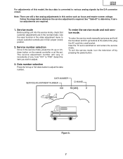
... press and hold the Vol-down button to adjust the data number. To exit the service mode, turn the television off by the D/A converter circuit. 32F630 32F631 For adjustments of one, from "V01" to "P08". Follow the steps below whenever the service adjustment is converted to various analog signals by pressing... AC cord into the service mode, check that customer adjustments are still a few analog adjustments in increments of this series such as focus and master screen voltage. Now the TV set .
... press and hold the Vol-down button to adjust the data number. To exit the service mode, turn the television off by the D/A converter circuit. 32F630 32F631 For adjustments of one, from "V01" to "P08". Follow the steps below whenever the service adjustment is converted to various analog signals by pressing... AC cord into the service mode, check that customer adjustments are still a few analog adjustments in increments of this series such as focus and master screen voltage. Now the TV set .

Service Manual
Page 10
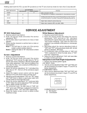
... 8. Select the service adjustment "V03" and reset data to "00". Alternately adjust the service adjustment data of "V09" and "V10" respectively. 5. Screen Adjustment 1. Select the service adjustment "V11" and reset data to obtain normal color level. 7. Get into service adjustment data "V01" and "V05"...channel to "00" (minimum color)(Record original data code under adjustment "V03" before changing). 32F630 32F631 Holding down both the VOL-up and CH-up buttons on the TV set at low brightness level. 6. SERVICE ADJUSTMENT RF AGC Adjustment 1. Select another channel. Enter...
... 8. Select the service adjustment "V03" and reset data to "00". Alternately adjust the service adjustment data of "V09" and "V10" respectively. 5. Screen Adjustment 1. Select the service adjustment "V11" and reset data to obtain normal color level. 7. Get into service adjustment data "V01" and "V05"...channel to "00" (minimum color)(Record original data code under adjustment "V03" before changing). 32F630 32F631 Holding down both the VOL-up and CH-up buttons on the TV set at low brightness level. 6. SERVICE ADJUSTMENT RF AGC Adjustment 1. Select another channel. Enter...
Service Manual
Page 11
... monoscope pattern. 3. Note 1 : You will have to come out of "V06", "V07" and "V08" respectively. 8. Adjust the master screen control until a good grey scale with normal whites at service mode for more than 2 seconds will PART REPLACED IC2001 IC201 IC2101 CRT IC3001 ADJUSTMENT ...V10" respectively. 5. Select another channel. Enter the service mode and select the service adjustment "R01". 3. 32F630 32F631 Holding down both the VOL-up and CH-up buttons on the TV set at low brightness level. 6. Receive a good local channel. 2. Enter the service mode and select...
... monoscope pattern. 3. Note 1 : You will have to come out of "V06", "V07" and "V08" respectively. 8. Adjust the master screen control until a good grey scale with normal whites at service mode for more than 2 seconds will PART REPLACED IC2001 IC201 IC2101 CRT IC3001 ADJUSTMENT ...V10" respectively. 5. Select another channel. Enter the service mode and select the service adjustment "R01". 3. 32F630 32F631 Holding down both the VOL-up and CH-up buttons on the TV set at low brightness level. 6. Receive a good local channel. 2. Enter the service mode and select...


